1
Installation and Operating Data
FOR YOUR SAFETY - This product must be installed and serviced by authorized personnel, qualified in pool/spa heater installation. Improper installation and/or operation can
create carbon monoxide gas and flue gases which can cause serious injury, property
damage, or death. Improper installation and/or operation will void the warranty.
Installation and
Operation Manual
LX™ and LT™
Gas-Fired Pool
and Spa Heater
Model
LX250
Shown
WARNING
If these instructions are not followed exactly, a fire or explosion may result,
causing property damage, personal injury, or death.
Do not store or use gasoline or other flammable vapors and liquids in the
vicinity of this or any other appliance.
•
•
•
•
WHAT TO DO IF YOU SMELL GAS
Do not try to light any appliance.
Do not touch any electrical switch; do not use any phone in your building.
Immediately call your gas supplier from a neighbor’s phone. Follow the gas
supplier’s instructions.
If you cannot reach your gas supplier, call the fire department.
H0214000B
Installation and service must be performed by a qualified installer, service
agency or the gas supplier.
TABLE OF CONTENTS
SECTION 1
General Information
SECTION 3
Operating Instructions
1A
1B
1C
3A
3B
3B-1
3B-2
3B-3
Introduction ............................................................ 1
Description ............................................................. 1
Warranty ................................................................ 1
SECTION 2
Installation Instructions
2A
2A-1
2B
2C
2C-1
2C-2
2C-3
2D
2E
2F
2F-1
2F-2
2F-3
2F-4
2F-4a
2F-4b
2G
2G-1
2G-2
2H
2H-1
2H-2
2H-3
2H-4
2I
2I-1
2I-2
2I-3
2I-4
2I-5
2J
2J-1
2J-2
2J-3
2J-4
2J-5
General Requirements .......................................... 1
Special Precautions ............................................... 1
Heater Assembly and Preparation ........................ 1
Heater Location ..................................................... 2
Installation Information .......................................... 2
Installation Clearances .......................................... 2
Flooring Typical Installation ................................... 2
Outdoor Installation ............................................... 3
Outdoor Shelter Installation (Canada) ................... 3
Indoor Installation .................................................. 3
Preparation of Heater For
Indoor Installation .................................................. 3
Special Location Requirement .............................. 4
Air For Combustion and Ventilation ...................... 4
Exhaust Venting .................................................... 4
Important Information On Vent Pipe Sizing ........... 4
Vent Pipe Sizing and Installation ........................... 5
Gas Supply and Piping .......................................... 5
General Instructions .............................................. 5
Special Precautions For Propane Gas .................. 8
Electrical Power ..................................................... 8
General Information ............................................... 8
Bonding ................................................................. 8
Auxiliary Time Clock Wiring ................................... 8
Remote Operation ................................................. 9
Water Piping ........................................................ 10
Reversal of Heater Water Connections ............... 10
Pool/Spa Piping Systems .................................... 13
Connections at Heater ......................................... 13
Pressure Relief Valve .......................................... 14
Automatic Chlorinators (Chemical Feeders) ....... 15
Start-Up and Adjustment ..................................... 15
Normal Operation ................................................ 15
Start-Up ............................................................... 15
Gas Pressure ....................................................... 16
Adjustment of Water Pressure Switch ................ 16
Water Temperature Rise ..................................... 17
3B-4
3C
3C-1
3C-2
3D
3D-1
3D-2
3D-2a
3D-2b
3D-2c
3D-2d
3E
3F
3G
3G-1
3G-2
3H
3H-1
3H-2
Start-Up Procedure ..............................................
Temperature Controls .........................................
Information Displayed ..........................................
Turning The Heater On Or Off .............................
Setting Pool And Spa Temperatures And
Changing From Fahrenheit To Celcius ...............
Error Status .........................................................
Lighting and Shutdown ........................................
Lighting the Heater ..............................................
Shutdown .............................................................
Water Chemistry ..................................................
Pools ....................................................................
Spas ....................................................................
Spa Water Chemistry ..........................................
Water Changing ..................................................
Corrosion .............................................................
Testing .................................................................
Spa/Hot Tub Safety Rules ...................................
Swimming Pool Energy Saving Tips ...................
Seasonal Care .....................................................
Spring and Fall Operation ...................................
Winterizing ...........................................................
Periodic Inspection ..............................................
Owner Inspection .................................................
Professional Inspection .......................................
18
18
19
19
19
19
21
21
21
21
21
21
23
23
23
23
23
23
24
24
24
24
24
25
SECTION 4
Specifications and Dimensions
4A
4A-1
4A-2
General Information ............................................. 25
Specifications ...................................................... 25
Dimensions .......................................................... 25
SECTION 5
Replacement Parts
5A.
5B
5C
5C-1
5C-2
General Information ............................................. 26
Part Numbers ...................................................... 26
Exploded View Of Heater .................................... 27
Overview Exploded View ..................................... 27
Detail Exploded View .......................................... 28
Warranty ................................................ Back Cover
LX and LT Pool Heaters
Page 1
SECTION 1.
General Information
SECTION 2.
Installation Instructions
1A. Introduction
2A. General Requirements
This manual contains information for the proper
installation and operation of the LX and LT pool/spa
heaters. Certain sections are specific to United States or
Canadian installations, and are labeled United States or
Canada. Procedures in this manual must be followed
exactly. To obtain additional copies of this manual contact
Waterpik Technologies. For address information see back
cover.
1B. Description
The Laars LX and LT have no standing pilot burner.
They exceed the requirements of energy conservation
regulations such as those in California, Hawaii, New York,
Oregon and other states which require that a pool heater
not have a continuous ignition source.
The heaters are designed to operate in conventional
swimming pool and spa equipment arrangements. They
require 120V or 240V, 60 Hz electrical power.
The Laars LX and LT are certified by International
Approval Services, Inc. to comply with latest editions of
applicable U.S./Canadian combined standard for gas-fired
pool heaters. In the United States, the applicable standard
is ANSI Standard Z21.56 for gas-fired pool heaters. In
Canada, it is Standard CSA 4.7. As such, the heater
carries both the AGA and CGA logos.
The heaters have been designed specifically to heat
fresh water swimming pools and spas, and with proper
installation and care, they will provide years of reliable
service. Do not use the heaters to maintain pool or spa
water temperature below 70°F. Do not use them as heating
boilers or general service water heaters or to heat salt
water. For special applications, consult your Waterpik
Technologies dealer.
DANGER
Improper installation or servicing can cause
property damage, injury or death due to fire,
asphyxiation or carbon monoxide poisoning.
1C. Warranty
The LX and LT are sold with a limited factory
warranty. A copy of the warranty is included in a plastic
bag inside the heater and on the back cover of this manual.
The home owner should fill out the warranty registration
card included in the plastic bag and return it to Waterpik
Technologies. The warranty does not cover damage caused
by improper installation, operation, or field modification;
or damage to the heat exchanger caused by corrosive
water. See Section 3D for guidelines on pool water
chemistry.
All gas-fired products require correct installation to
assure safe and satisfactory operation. The requirements
for pool heaters include the following:
1.
Appropriate site location and clearances.
2.
Sufficient supply of clean air for combustion and
ventilation.
3.
Proper venting of products of combustion.
4.
Properly sized gas pipe.
5.
Properly sized gas meter.
6.
Adequate water flow.
In the United States, installation must be in
accordance with local codes and the most recent edition of
the National Fuel Gas Code, ANSI Z223.1. The Code can
be obtained from:
National Fire Protection Association
1 Batterymarch Park
Quincy, MA 02269
In Canada, install the heater in accordance with
local codes and the most recent edition of the Installation
Codes for Gas Burning Appliances, CAN 1-B149.1 & .2.
The Canadian Gas Codes are available from:
Canadian Gas Association
55 Scarsdale Road
Don Mills, Ontario
M3B 2R3
2A-1.Special Precautions
Liquefied petroleum (LP) gas is heavier than air.
Therefore, a pool heater using LP gas is subject to special
installation rules. Consult local codes and fire protection
authorities about specific installation restrictions.
Fuel gas and its combustion products are known to
cause cancer or harm the reproductive process. Follow
these installation instructions and applicable codes exactly
to avoid this hazard.
2B. Heater Assembly and Preparation
The LX or LT can be installed in a variety of ways,
some of them requiring preparation or assembly in the
field. Water connections are provided on the right side of
the heater but can be changed to the left side by reversal of
the heat exchanger.
Page 2
It is best to handle these preparations before the
heater is installed in its final location. Instructions are
provided in subsequent sections of this document.
Contact Waterpik Technologies regarding
installations at elevations above 3,000 feet (980 m). It is
necessary to make changes to the burner tray to assure
proper operation.
2C. Heater Location
2C-1. Installation Information
The LX and LT can be installed outdoors or indoors
as outlined in later sections. In either case location must
be selected with consideration of vent gas exhaust and in
the case of indoor installation, the location must have
suitable provisions for combustion and ventilation air.
Avoid placing the heater in locations where it can
cause damage by water leakage. If this is not possible,
provide a suitable drain pan to catch and divert any
leakage. The pan must not block natural flow of air to or
around the heater.
When a heater or any system component is located
below the pool surface a leak can result in large scale
water loss or flooding. Waterpik Technologies cannot be
responsible for such water loss or flooding. Location of a
heater below or above the pool surface affects operation of
the heater pressure switch. See sections on water piping
and heater start-up for more information about this.
NOTE: See Outdoor Installation section regarding
roof overhang.
These clearances are the minimum acceptable.
Whenever possible, larger clearances should be provided to
assure adequate room for service operations. Note that gas
piping may be provided through either side of the unit. See
later section on gas piping.
Do not install the heater on carpeting or similar
material.
2C-3. Flooring - Typical Installation
The heater must not be installed on combustible
flooring without special measures to assure that the floor
temperatures will not be excessive.
A special base for combustible floors may be
obtained from Waterpik Technologies. The part number
appears in the parts list at the back of this manual (see
Section 5)
In the United States, the National Fuel Gas Code
allows a heater to be placed on a combustible surface when
there is a platform under the heater made of hollow
masonry no less than 4 inches (102 millimeters [mm])
thick, covered with sheet metal at least 24 gauge thick and
extending beyond the full width and depth of the heater by
at least 6 inches (76.2 mm) in all directions. The masonry
must be laid with ends unsealed, and joints matched to
provide free circulation of air from side to side through the
masonry (see Figure 1).
CAUTION
When pool equipment is located below the
pool surface, a leak from any component can
cause large scale water loss or flooding.
Waterpik Technologies cannot be responsible
for such water loss or flooding or resulting
damage.
2C-2. Installation Clearances
Clearances between the heater and combustible
material must be per Table 1.
Table 1.
Minimum Heater Clearances from
Combustible Surfaces
A ll In s ta lla ti o n s
S id e o f
H e a te r
U .S . a n d C a n a d a
inc h
(c m )
B la n k
4
(1 0 .2 )
Rear
4
(1 0 .2 )
P ip ing
12
(3 0 .5 )
To p
39
(9 9 .0 )
F ro n t
18
(4 5 .7 )
Notes:
1. Blocks must provide solid base and be braced so they
cannot slip out of place.
2. Air openings in blocks must be arranged to provide
unrestricted opening through entire width or length of
base.
Figure 1. Non-Combustible Platform.
LX and LT Pool Heaters
2D. Outdoor Installation
The LX and LT heaters can be installed in the
outdoor configuration as received from the factory.
Locate the heater in an open, unroofed area. Do not
install the heater under a deck. Do not locate the heater
below or adjacent to any doors, windows, louvers, grills,
etc., which connect in any way with an inhabited area of a
building, even though the access might be through another
structure (e.g., a garage or utility room. In the United
States there must be a minimum of 4 feet (1.22 m)
horizontally or vertically between the heater and any door,
glass opening, or gravity inlet to a building (see Figure 2).
DANGER
United States
Do not install the heater with the top of the
vent assembly within 4 feet (1.22 m) of any
opening into a building.
Canada
Do not install the heater with the top of the
vent assembly within 10 feet (3.05 m) of any
opening into a building.
If the heater is installed under an overhang, there
must be a minimum clearance of 5 feet (1.5 m) above the
top of the heater and the structure should not overhang the
heater more than 12 inches (0.30 m). The area under the
overhang must be open on three sides.
If the heater is installed close to a structure, protect it
Page 3
2E. Outdoor Shelter Installation (Canada)
An outdoor shelter is an unoccupied enclosure which
does not communicate directly with occupied areas. The
LX and LT may be installed in such a shelter only when
the installation is in accordance with local codes and the
most recent edition of Standard CAN/CGA B-149. These
codes and standards and Waterpik Technologies require
that the heater be properly vented as outlined in this
manual. Other requirements also apply, such as provision
of ample uncontaminated air for combustion and
ventilation.
2F. Indoor Installation
2F-1. Preparation of Heater for Indoor
Installation
If the LX or LT is to be installed indoors, its exhaust
discharge grill must be converted to a collar for vent pipe
connection. The necessary vent collar, gasket and screws
can be ordered as parts kit R0331403 or R0331405 (see
parts list in Section 5 of this manual). The conversion can
be done quite simply as follows:
1.
2.
3.
4 ft (1.22 m)
Figure 2. Outdoor Heater Installation.
from rain water runoff by means of gutters, roof water
diverters or similar measures. Do not locate the heater
close to irrigation sprinklers. Water from sprinklers may
damage controls and electronic components.
Avoid locations where wind deflection off nearby
structures might cause wind loading and downdraft
conditions. Where downdraft conditions exist, locate the
heater at least 3 feet (0.91 m) from vertical surfaces (e.g.,
nearby buildings and walls).
Install the heater at least 5 feet (1.52 meters) from
the inside wall of the pool or spa unless the heater is
separated from the pool or spa by a five-foot (1.52 meter)
high solid fence, wall or other permanent barrier.
Remove the vent exhaust grill by removing the
four screws which retain it. The grill and the
screws may be discarded (See Figure 3).
Replace the grill with the vent collar (see section
4 for kit number). Place the vent collar and
gasket over the hole and fasten it in place with
the 4 screws provided. Be sure that all
components are properly aligned (See Figure 4).
Install the vent pipe on the indoor vent collar.
The collar will accommodate vent piping of
nominal 7" or 9" diameter, depending upon the
model of your heater (See Figure 5). See vent
installation section for important information on
selecting proper pipe size.
OUTDOOR
VENT GRILL
Figure 3. Removal of Outdoor Exhaust Grill.
Page 4
INDOOR
VENT
COLLAR
GASKET
inch of flow area for each 4000 BTU/H of heater input. If
air is provided through horizontal ducts, each opening and
duct must provide one square inch of flow area for each
2000 BTU/H of heater input. These requirements are
summarized in Table 2. Note that the specified areas are
net free area, after allowing for the blockage of grill bars,
etc. See applicable codes for details.
Even though local codes may allow it, Waterpik
Technologies does not recommend installation in which
combustion and ventilation air is provided by infiltration.
Pool heaters tend to have larger input than many
appliances and it is best to specifically provide combustion
air means.
Table 2. Air Openings to Outside
Required Net Free Open Area
for Combustion Air Openings
Figure 4. Vent Collar Assembly for Indoor Installation.
Model
Direct from outside
in2
(cm2)
Duct from outside
in2
(cm2)
250
63
(406)
126
(813)
400
100
(645)
200
(1290)
2F-4. Exhaust Venting
2F-4a.Important Information on Vent
Pipe Sizing
Figure 5. Vent Pipe Installation.
2F-2. Special Location Requirement
Virtually all local installation codes require that a
heater installed in a garage or similar structure be on a
platform at least 18 inches (46 cm) above the floor. This
requirement is in consideration of possible existence of
combustible fumes at floor level. Consider such
installations carefully and do not proceed if there is any
possibility of such fumes being ignited by the heater.
2F-3. Air For Combustion and
Ventilation
It is very important that the heater be provided with
adequate air for combustion and to ventilate the space in
which it is located. Provide combustion and ventilation air
as specified in local codes, or in their absence per the
National Fuel Gas Code ANSI Z223.1 or the Canadian
Installation Codes for Gas Burning Appliances, CAN 1B149.1 & 2.
In general, the codes require that the space in which
the heater is located be provided with two combustion air
openings, one within 12 of the floor and one within 12
of the ceiling (see Figure 6). If air is supplied directly
from the outside, the openings must provide one square
When converted to indoor venting configuration, the
LX and LT heaters have a vent collar fitting. The
diameter of the vent collar and, thus, the minimum
diameter of the vent pipe to be used is determined by the
model of heater installed. The only correct procedure for
vent pipe sizing is to do so in accordance with table 3 and
the applicable installation code as stated in the "Danger"
warning below.
Table 3. Vent Pipe Sizing Table
LX
M odel
V e n t P i p e D i a m e te r
inc h
(c m )
250
7 .0
1 7 .8
400
9 .0
2 2 .9
DANGER
Vent pipe diameter must be as required by
the National Fuel Gas Code Z223.1 or the
Canadian Installation Codes for Gas
Appliances CAN 1-B149.1 & 2. Undersize pipe
can result in inadequate venting and oversize
pipe can result in vent condensation. In either
case the result can be release of combustion
products to the indoors. This can cause
serious injury or death by carbon monoxide
poisoning or asphyxiation.
LX and LT Pool Heaters
Page 5
ROOF JACK
FOR GARAGE
INSTALLATION
BASE OF HEATER
MUST BE A
MINIMUM OF 18
INCHES (46 CM)
ABOVE THE
FLOOR
2)
Figure 6. Indoor Installation Venting (USA), or Outdoor Shelter (Canada).
2F-4b.Vent Pipe Sizing and
Installation
As part of their certification, the LX and LT have
been determined to be a Category I Fan-Assisted
appliance. They are intended for standard vertical venting
per tables provided in most local codes for Category I FanAssisted appliances. If the local code does not include
such tables, refer to the National Fuel Gas Code Z223.1 or
the Canadian Installation Codes for Gas Appliances CAN
1-B149.1 & 2. Note that the tables for fan-assisted
appliances include both maximum and minimum vent
loading figures. The primary purpose of the maximum
ratings are to assure that the vent operates with negative
pressure throughout its length. The minimum ratings are
to assure that vent gases dont cool too much and thereby
assure that condensation doesnt occur.
It is important that all aspects of venting installation
be in accordance with local codes, or in their absence, the
cited national codes. Vent diameter, height, allowable
length of horizontal runs, vent cap requirements, location
and height of vent terminations on a roof, and many other
important matters are covered in these codes. Proper
installation of the LX and LT heaters requires that all
these factors be correctly handled.
1.
The gas supply must be able to provide gas at
pressures specified in Table 5.
2.
Gas piping installation must be in accordance with
the latest edition of ANSI Z223.1. In Canada, the
installation must be in accordance with CAN- B149.1
or .2 and all local codes that apply.
3.
Check the rating plate to make sure the heater is
fitted for the type of gas being used. Waterpik
Technologies heaters shipped from the factory are
certified to operate at an altitude of 0 to 3000 feet (0
to 915 m) for natural gas and 0 to 5000 feet (0 to
1525 m) for propane, or if so ordered, at higher
altitudes. In the United States, the heater manifold is
marked with a tag or sticker indicating one of the
following high altitude operation codes:
FOR NATURAL GAS
a.
High altitude (H) - 3,000 to 6,000 feet
(915 to 1830 m)
b. High altitude (J) - 6,000 to 10,000 feet
(1830 to 3050 m)
FOR PROPANE GAS
a. High altitude (H) - 5,000 to 10,000 feet
(1525 to 3050 m)
2G. Gas Supply and Piping
2G-1.
General Instructions
Review the following general instructions before
continuing the installation.
4.
In Canada, the heater rating plate is marked for
specific altitude requirements as follows:
FOR NATURAL GAS
a.
Factory Released - 0 to 2,000 feet
(0 to 610 m)
Page 6
b.
5.
High altitude (H) - 2,000 to 4,500 feet
(610 to 1370 m)
FOR PROPANE GAS
a. Factory Released - 0 to 4,500 feet
(610 to 1370 m)
Use only wrought steel piping or when permitted by
local codes, other rigid piping material. Do not use
flexible gas connectors, which restrict gas flow to the
heater.
6.
Table 4 specifies sizing for gas supply piping based
on 1/2 WC (3.45 kPa) pressure drop in the piping.
Larger piping may be necessary if the local gas
supply is at pressures which will not guarantee
adequate pressure at the heater. Table 5 specifies the
maximum and minimum supply pressures necessary
at the heater when it is operating.
7.
Install a sediment trap (drip leg) ahead of the gas
controls (see Figure 7). Fit the trap with a threaded
cap which can be removed for cleaning.
8.
Install a manual gas shut-off valve for service and
safety. Do not use a restrictive gas cock.
CAUTION
Permanent damage to the gas valve will occur
if the following procedures are not followed.
9.
Disconnect the heater and its individual shutoff valve
from the gas supply system during pressure testing of
the system at pressures higher than 1/2 pounds per
square inch (psi) (3.45 kilopascals [kPa]). If the test
pressure is equal to or less than 1/2 psi (3.45 kPa),
close the manual shutoff valve on the heater during
the piping pressure test.
Table 4. Natural Gas Pipe Size Requirements
Distance from Gas Meter
Heater
Size
0-50 feet
(0-15 m)
in.
50-100 feet
(15-30 m)
in.
100-200 feet
(30-60 m)
in.
250
1
1-1/4
1-1/4
400
1-1/4
1-1/2
1-1/2
Notes:
1. These numbers are for natural gas (0.65 Sp. Gr.) and
are based on 1/2 inch (3.45 kPa) water column pressure
drop. Check supply pressure with a manometer, and
local code requirements for variations. For liquefied
petroleum gas, reduce pipe diameter one size, but
maintain a 3/4 inch minimum diameter.
2. Check supply pressure and local code requirements
before preceding with work.
Table 5. Gas Supply Pressure Requirements
Supply Pressure
Natural Gas
Propane Gas
Water Column
in.
(kPa)
in.
(kPa)
Minimum
Maximum
6
(1.5)
10.5 (2.7)
11
14
(2.8)
(3.5)
10.
If the gas supply pressure is less than required, check
for undersized pipe between the meter and the heater,
a restrictive fitting, or an undersized gas meter. Gas
supply pressures to the heater, when it is operating,
are listed in Table 5.
NOTE: The maximum inlet gas pressure must not
exceed the specified value. The minimum value listed is
for the purpose of proper heater operation. Refer to Table
Manual Shutoff
Valve
11.
Gas Supply
Inlet
Union
T-Fitting
3" Min.
Nipple
To
Equipment
Inlet
Cap
Figure 7. The Proper Design for a Sediment Trap/Drip
Leg.
To connect the gas supply line to the heater's gas
valve, you must first install a steel elbow (supplied
with the heater in the installation and instruction
box). Screw the elbow into the inlet side of the gas
valve. The heater is designed so that the gas supply
line may enter through either side of the heater. Hand
tighten the elbow until the desired orientation is
achieved.
CAUTION
Do not over tighten the elbow. Over tightening
will crack the gas valve. Do not use teflon tape
to wrap the elbow threads.
LX and LT Pool Heaters
Wiring Diagram
Page 7
(6 8) 5( 05 2)6 1$57
$
.%
`
9 '1 ' + /$
* 1, 7 9
5
<
* %.
53
+& + 7, 6(+
7, *, ,0 &,7
/
+
:
6
:
6
36 36
5%
.%
/ 5
% % *
<
$
5
*
$/8 7(
6
$1 (5
0
+
,7&
:
716
9(
(
(5: 568
2/ (65
% 3
+&
7,
:
6
: :
53
J4-2
%.
6$ 9(/
* $9
71 71
9( (9 63 63
: :
(
6
1
6(
(
0
$
/
)
J4-1
5
(
,7
1
*
,
'
(
5
(7
,
+
:
<
* 25
3 5 :
99
00
<
9 9
0 0
<
.%
.
%
.%
5%
5
:
%5
:
+
,7
:
(7
,
+
:
(
&
$
5
7
(
.
& 5 & <
$
/ $
% :5
7 :
(
&
$
5
7
:
/2
/(
<
.
*5%
<
1'8 :
25 (5
* &6
9 9
5
2 .% 5
,13 *8
/
3
*
5%
53
:
:
.%
5
.%
<
*
:
'1 5(
* &6
5%
:
5%
%. %/ 5 <
:
.%
:
5
:
:
<
*
:
(/
,13 $&7
3(
(&
5
5
<.
%
:
5
<
5
.%
2
.%
<
*
/%
:
:
<
<
2
5
*
/%
.%
/%
%.
<
:
2
:
*
:
/%
*
5
5
%.
5
: .% : 5
:
:
*
.%
(/
3
5
8
3
+
,7
:
(7
,
+
:
.
%
:
.%
`
`
`
`
5( (58
7$ 66
: (53
1
((
5
*
(
*
1
$
5
2
.%
.%
5
5
<.
%
53
'1
82 (:
5* 56&
:
5
<
:
<
.%
: :
:
Figure 8. LLD Connection/Schematic Wiring Diagram.
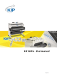
CAUTION: Do not connect the power of the heater to the "load" or output side of a filter pump relay or time clock.
The fan on this heater must have power to run after the filter pump has been shut off.
12 /25
7,, 71
*1, 2&
1
:
2
5
%
(
&
$
5
7
:
/2
/(
<
'
(
5
+
7,
:
(
7,
+
:
6285&(
*
TEMP
SENSOR
<
.
%
&$9
5( 05 2)6 1$57
&$9
'1 * < $ :( &$5
(
/8
%
`
<
:
.
&
$
/%
(
&
$
5
7
:
/2
/(
<
+
,7
:
1
((
5
*
<
*
+($7(5
` 32:(5
5
.%
+
7,
:
.
&
/$
%
<
.
%
:
2
//
(<
<
Page 8
12.
Before operating the heater, test the complete gas
supply system and all connections for leaks using a
soap solution. Do not use an open flame.
CAUTION
Some leak test solutions (including soap and
water) may cause corrosion or stress cracking.
Rinse the piping with water after testing.
2G-2.
Special Precautions for
Propane Gas
Liquefied petroleum (LP) gas is heavier than air.
Therefore, do not install pool heaters using LP gas in pits
or locations where gas might collect. Locate heaters a safe
distance from LP gas storage and filling equipment.
Consult local codes and fire protection authorities about
specific installation restrictions.
2H. Electrical Power
wires that lead to a two position terminal block located
next to the connector. Remove the two wires from the
terminal block. Take the fifteen-pin connector assembly
with the black wires from the installation and instructions
box. It is marked "120V". Connect the two long wires to
the two position terminal block. Either wire may be
connected to either tab on the terminal block, the
connections are not polarity sensitive. Plug the fifteen-pin
connector into the receptacle. The connector is keyed so it
will fit in only one orientation.
Electrical wiring must be in accordance with the
latest edition of the National Electric Code (NEC), ANSI/
National Fire Protection Association (NFPA) 70, unless
local code requirements indicate otherwise.
CAUTION
DO NOT connect power to the LX or LT pool
heater from the load side of a filter pump relay
or time clock.
2H-1.General Information
Wiring connections must be made exactly as shown
in the wiring diagram found on the inside of the heater
(see Figure 8 ). Grounding must be provided as required by
the prevailing electrical code. A separate bonding wire
MUST be provided as indicated in the following section
The heater comes factory-wired intended for use with
240 Volt, 60 Hz AC field electrical supply. To convert to
120 Volt, 60 Hz AC requires the changing of the fifteenpin connector assembly on the component raceway.
Remove the fifteen-pin connector from the receptacle
located directly below the fan intake on the raceway. All
the wires on the connector are red and the connector is
marked "240V". The fifteen-pin connector will have two
CONNECT
WIRES
INSIDE
HEATER
WIRES
AS
SHIPPED
CONDUIT
ELBOW
To wire the Laars LX or LT heater:
1.
Wire the heater to a 120V or 240V /60 Hertz (Hz)
electrical source.
2.
Connect the wires from the source to the leads on the
right side of the heater in the space behind the
raceway (see Figure 9).
NOTE: No external junction box is required.
2H-2. Bonding
The National Electrical Code and most other codes
require that all metallic components of a pool
structure, including reinforcing steel, metal fittings and
above ground equipment be bonded together with a solid
copper conductor not smaller than a number 8 wire. The
heater, along with pumps and other such equipment must
be connected to this bonding grid. A special labeled
bonding lug is provided on the right side of the heater to
accommodate this requirement.
2H-3. Auxiliary Time Clock Wiring
If you install a time clock to control the filter pump
operation, it is recommended that the time clock have its
own low voltage (Firemans) switch to turn off the heater
before turning off the pump . The switch should shut off
the heater about 15 minutes before the filter pump shuts
off. This will allow for a more efficient operation by
removing any residual heat contained in the heat
exchanger back to the pool.
To install a time clock auxiliary switch into the
heater circuit, follow these instructions (see Figure 10):
1.
Figure 9. Field Wiring Connections.
Remove heater door.
LX and LT Pool Heaters
Page 9
2.
Remove the factory installed jumper wire and tag
from the terminal strip (see Figure 10).
3.
Connect the low voltage wires from the time clock
auxiliary switch to the two terminals. Use American
Wire Gage (AWG) No. 14 gauge stranded copper
wire with a temperature rating of 221°F (105°C) or
greater (see Figure 11).
2H-4. Remote Operation
(Model LX Only)
LEFT SIDE OF
RACEWAY
REMOVE JUMPER
WIRE
TERMINAL BLOCK
Figure 10. Remove Jumper from Terminal Block
Figure 11. Typical Time Clock Wiring.
INDOOR CONTROL
Bezel
RS CONTROL
SYSTEM
J4
U1
W0
22 GAGE, 4
CONDUCTOR
WIRE
JVA Board
1
2
3
4
1
RED
BLK
YEL
GRN
8
1
If your time clock simply interrupts the high
voltage power supply or has a high voltage output, do not
connect the power supply of the heater to the output
side of the clock. Doing so will prevent the blower from
purging the residual heat from the heater when the heater
turns off. This situation will damage the heater. The
blower must be allowed to run for 45 seconds after the
heater shuts off.
5 1
LX CONTROL
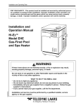
Figure 12. Wiring a Laars LX to a Jandy RS Remote
The Laars LX pool/spa heater controls can be wired
for remote operation. All Waterpik Technologies/Jandy RS
Control Systems will permit the heater to be operated by
remote control. If you are setting up a new pool or spa
system, call your local distributor or the Waterpik
Technologies/Jandy Customer Service Department for
information on the correct RS Control System to meet your
needs.
To connect a Laars LX heater to an existing RS
Control System, first determine the revision level the
programmed chip in the RS Control System's Power
Center Board. To check the revision level of the chip,
press and hold the reset button on the side of the indoor
control panel for 10 seconds then release it. A number will
appear on the display for approximately 5 seconds. This
first number can be ignored. After the first number
disappears, a second number will appear in the display
window. It will consist of 4 digits followed by a revision
level ("#### REV _"). If the revision level displayed here
is at "H" or higher it will accommodate a Laars LX heater
without any modification. If the chip is at a revision "G" or
lower the chip will have to be replaced with a newer
version. An alternate method for determining the revision
level of the programmed chip in your RS control, is
described in steps 1-4 below. An updated chip can
obtained through Waterpik Technologies/Jandy by
ordering the PPD Kit. Instructions for changing the chip
are in the kit.
Do not connect more than two wires to any of the
terminals in the RS Control System when connecting
peripheral devices. If connecting the LX heater to the RS
Control System creates this situation, then a Multiplexing
PCB kit must be used. Call your distributor or Waterpik
Technologies to order the kit.
To connect the Laars LX to your RS control System,
follow the steps listed below (See fig. 12).
1. Turn off the power to the heater and the RS
Control.
2. Open the RS Power Center Enclosure and
remove the front dead panel.
NOTE: Only a revision H or higher program chip in
the RS system will support the LX Heater
Interface.
Page 10
3.
Remove the two screws holding the bezel in
place. Turn the bezel over to view the circuit
board on the back.
4. Locate the programmed chip on the Power
Center Board (the larger square chip in the
lower right corner of the circuit board). In the
center of the chip is the revision letter. If the
revision letter is "H" or higher go to step 5. If
the revision level is "G" or lower, replace the
chip. Directions for removal and installation of
the chip are provided in the new PPD Kit .
NOTE: If ordering a new programmed chip, be sure to
order the part number printed on the chip
currently in your RS control .
5. Use 22 gauge 4-conductor wire (WP/J part #
4278) to run between the heater and the RS
control, and match the wire color order.
The wires coming from the LX heater can be
doubled up on the red terminal bar with the
four wires coming from the indoor controller.
NOTE: If you need to install more than two wires in
each terminal, order a Waterpik Technologies/
Jandy Multiplex PCB Kit, which includes the
Multiplex Board (WP/J part # 6584). Never put
more than two wires into each of the pins of the
terminal bar.
7. On the heater's electronic control board, verify
that the water temperature sensor is connected
(J4), and that jumper is in place on W0.
8. Check all wiring, then apply power to both the
heater and the RS control system. Operation can
be verified in either Service or Auto mode. See
your RS Control System for instructions about
operation.
Figure 13. Water Connection as Shipped.
6.
When the LX heater is first powered, the display on
the control will show "RS ONLINE". If there is an RS
control connected to the heater, it will sense the RS unit
and remain online. When the display shows "RS
ONLINE" all functionality of the control on the heater is
disabled. The heater functions can be controlled only at the
RS unit. However, sensor data is displayed at both the
heater and the RS unit.
To temporarily use the heater controls, use a thin
object to depress the button marked "RS SERVICE". The
"RS ONLINE" indicator will disappear from the heater
display. All functionality has now been returned to the
control on the heater. In this mode the RS unit has been
disabled. To return the functionality to the RS unit, push
the button again.
An interrupt (on/off) type remote can be connected
by removing the jumper wire on the terminal block located
in the control compartment (see Figure 8) and connecting
the two wires from the remote to the two terminals on the
terminal block. This type of remote control will turn the
heater on or off, but will not perform any other function.
Figure 14. Water Connection Reversed.
Consult with Waterpik Technologies Service
Department with questions about installing remote
controls manufactured by companies other than Waterpik
Technologies.
2I. Water Piping
2I-1.
Reversal of Heater Water
Connections
The LX and LT are shipped with water connections
on the right side, but they can be modified in the field to
provide left-side water connections. This procedure
involves removing the heat exchanger and reinstalling it
opposite to it's original position. Some of the heater wiring
and control components must be relocated, so this
procedure must be done only by a trained service
technician.
Heat exchanger reversals are generally done before
the installation of power and water to the heater. If you
need to reverse the heat exchanger on a previously
installed heater be sure that all electrical power and water
supply has been turned off before starting the procedure.
Water connection reversal is illustrated in Figures 13 and
14. Proceed as follows:
1.
Remove the heater front panel (door).
LX and LT Pool Heaters
2.
3.
Remove the two hex head screws that hold the
raceway cover in place. They are located on the
bottom flange of the raceway cover. Slide the raceway
cover down to expose the raceway.
Remove the control panel assembly from the top
panel. Lift the control panel cover. Remove the two
philips head screws located at the front edge of the
bezel. Lift the front of the bezel up until the entire
assembly comes away from the top. Without
removing any wires, slip the control assembly
through the hole so that when the top is removed, the
control assembly will stay with the heater.
4.
Remove the four philips head screws that fasten the
vent grill to the top. Remove the vent grill.
5.
Remove the top. There are two hex head screws at the
upper corners of the raceway. And there are two
philips head screws at the upper corners of the rear
panel.
6.
Disconnect the blower pressure switch rubber tubing
from the blower assembly housing.
7.
Disconnect the two white wires from the vent switch
located just above the inlet/outlet header.
8.
Remove the EMI shield (metal plate) covering the
motor on the blower.
9.
Disconnect the five blower wires from the terminal
strip on the back of the raceway.
10.
Remove the four hex head screws holding the blower
to the flue collector. Lift the blower and the exhaust
vent off of the flue collector.
11.
Remove hex head screws holding the flue collector to
the top of the combustion chamber. There are 10
screws on a model 400 and 6 screws on a model 250.
Remove the flue collector and set it aside.
12.
Remove the water pressure switch's copper siphon
loop tube from the header by first loosening the brass
nut at the pressure fitting. Then carefully pull the
tube out of the fitting. There should be about two
inches of tubing inside the header. Be careful not to
create any kinks in the tubing when handling it.
13.
Clip the wire tie that bundles the wire harnesses
leading from the control panel. Disconnect the two
black temperature sensor wires from the back of the
control panel. Coil the wires and place them on top of
the heat exchanger.
14.
Disconnect the high limit switch black wires from the
wire harness leading to the control panel. There are
quick disconnects at the end of the wires.
15.
Remove the inlet/outlet header side cover plate
located under the inlet/outlet header. There are four
philips head screws, one in each corner, holding it in
place.
Page 11
16.
Slide the upper right side panel up and out of the
corner posts and place it aside.
17.
Remove the left side cover panel, held to the lower
panel with two philips head screws at the corners.
18.
Remove the flat return header side cover plate to
expose the return header by removing the four philips
head screws, one in each corner.
19.
Slide the upper left side panel up and out of the
corner posts and place it aside.
20.
Remove the end baffles from the heat exchanger.
WARNING
The heat exchanger is heavy.
It may be necessary to have help lifting the
heat exchanger to remove it and replace it on
the combustion chamber.
21.
Lift the heat exchanger assembly off of the
combustion chamber and rotate it 180° so that the
inlet/outlet header is on the left side of the heater.
22.
Carefully place the heat exchanger assembly back on
top of the combustion chamber. Be sure that the heat
exchanger is level and that the finned tubes fit
between the front and rear walls of the combustion
chamber. Be sure that the definned section of the
tubes, near the headers, fit into the slots cut in the top
of the insulation on the side walls of the combustion
chamber.
23.
Reinstall the end baffles on the heat exchanger. Align
the cut out portion of one of the baffles with the cut
out section on the top of the front combustion
chamber wall. Set the baffle so that the flange fits
completely over the combustion chamber wall. Set the
other baffle on the rear combustion chamber wall in
the same manner.
Note: There is no cut out section on the rear combustion
chamber wall.
24.
Carefully bend the water pressure switch's copper
siphon loop tube so that it reaches the inlet/outlet
header now on the left side of the heater. Do not
straighten out the coil behind the raceway and do not
kink the tubing. Straightening the coil or kinking
the tubing may result in poor heater operation. Insert
the end of the tube into the fitting on the header.
Tighten the nut onto the fitting one half turn past
hand tight.
25.
Route the wires that attach to the high limit switches
along the copper siphon loop, back to the right side of
the heater. Reconnect the wires to the wire harness.
Page 12
26.
Route the wires that attach to the temperature sensor
along the copper siphon loop, back to the right side of
the heater. Reconnect the wires to the tabs on the
back of the control panel (marked as J4-1 and J4-2).
27.
Use plastic wire ties to refasten the temperature
sensor and high limit switch wires to the copper
siphon loop. Bundle the wires near the control panel
and fasten them with a wire tie.
28.
Replace the flue collector so that the blower mount is
in the same position as it was before the heat
exchanger reversal. Be sure that the bottom of the
flue collector lies flat on the top of the combustion
chamber and that it covers all of the heat exchanger
tubes. Replace the hex head screws to fasten the flue
collector to the combustion chamber.
29.
30.
Reassemble the blower and exhaust vent to the flue
collector. Be sure that the blower is seated properly
on the gasket and fasten it to the flue collector with
four hex head screws.
Reconnect the fan wires to the terminal strip as
follows: (Terminal numbers are shown on wires
connected to the bottom of the terminal strip)
a. Black Blower wire to terminal 11
b. Blue Blower wire to terminal 10
c. Red Blower wire to terminal 9
d. Yellow Blower wire to terminal 8
e. White Blower wire to terminal 7
31.
Reconnect the two white wires to the vent switch now
located just above the return header.
32.
Reconnect the blower pressure switch tubing to the
blower housing.
33.
Replace the EMI shield (metal plate) located over the
blower by reinstalling the two hex head screws.
34.
Slide the upper right side panel back into the corner
posts on the right side of the heater. Push it down
until the tabs on the panel lock into the top of the
corner posts.
36.
Install the flat return header side cover plate
(removed from the left side of the heater) on the right
side to cover the return header by replacing the four
philips head screws, one in each corner.
37.
Slide the upper left side panel back into the corner
posts on the left side of the heater. Push it down until
the tabs on the panel lock into the top of the corner
posts.
38.
Remove the button plug from the inlet/outlet side
cover plate.
39.
Reinstall the inlet/outlet header side cover plate
located under the inlet/outlet header. It is held with
four philips head screws, one in each corner.
3-WAY
JANDY
CHANGEOVER
VALVE
3-WAY
JANDY
CHANGEOVER
VALVE
Figure 15. Typical Water Piping.
LX and LT Pool Heaters
Page 13
COUPLING NUT
O-RING
PVC OR CPVC PIPE
COUPLING
Figure 16. Piping to Heater.
Note: Only the small tab of the top groove will fit behind
the upper panel.
40.
Remove the button plug type washer from the left
side cover panel. This panel will not be used in
reassembling the heater after a heat exchanger
reversal. However, the button plug washer will be
needed. Do not replace the cover panel over the vent
switch outlet. Doing so may cause the heater to
malfunction.
41.
The gas line may enter the heater from either the left
side or the right side. Replace the button plug washer
in the hole through which the gas line will enter the
heater.
42.
Use the button plug to cover the hole on the opposite
side of the heater.
Note: Be sure that the white fiber gasket is positioned on
the top flange of the exhaust vent.
43.
Replace the top. While positioning the top, pull the
control panel through the hole and place it on top of
the panel. Fasten the top to the heater by replacing
the two hex head screws at the upper corners of the
raceway and the two philips head screws at the upper
corners of the rear panel.
44.
Position the vent grill over the exhaust vent. Replace
the four philips head screws that fasten the vent grill
to the top.
45.
Reinstall the control panel assembly into the top
panel. Slide the back of the bezel into place, then
lower the front, aligning the holes in the bezel with
the holes in clips on the tabs on the top panel.
Replace the two philips head screws located at the
front edge of the bezel.
46.
Slide the raceway cover up to the top of the heater. Be
careful not to pinch any wires. Replace the two
screws on the bottom flange to hold the cover in
place.
47.
Replace the front panel (door).
2I-2.
Pool/Spa Piping Systems
Figure 15 illustrates typical piping for pool
equipment in pool/spa combination pools. With their
electronic temperature controls, the LX and LT are
particularly suited for this type of pool installation.
The heater must be protected from back-siphoning of
water, which can result in dry starts. If there is any chance
of back-siphoning, provide a check valve between the pool
and the filter pump inlet.
Arrangement of pool system components other than
as illustrated in these diagrams can affect the operation of
the heaters water pressure switch. Location of the heater
above or below the pool water surface can also affect
operation of the switch. In general, the pressure switch can
be adjusted to accommodate this effect if the heater water
connections are no more than six feet below the pool water
surface and no more than 15 feet above it. See instructions
for pressure switch adjustment in the heater start-up
section of this manual for more information about this.
Note that when pool equipment is located below the
pool surface a leak can result in large scale water loss or
flooding. Waterpik Technologies cannot be responsible for
such water loss or flooding or the damage caused by it.
Do not install a shutoff valve or any kind of variable
restriction in the water piping between the heater outlet
and the pool/spa.
Pool systems with water flow rates higher than 125
GPM require an adjustable external bypass at the heater.
Page 14
2I-3.
Connections at Heater
The LX and LT have a standard two inch water
header and coupling design. With this feature, only
nominal two inch PVC or CPVC may be connected to the
heater. However, by installing the appropriate pipe
adapters and two short pieces of two inch plastic pipe
(supplied by the installer), any size existing pipe may be
fitted to the heater.
To connect a section of 2 PVC or CPVC pipe to the
heater, first slip a coupling nut onto the pipe. Then
prepare the end of the pipe with the proper PVC/CPVC
primer and glue. Follow the manufacturers instructions
provided with the primer and glue for preparation
procedures and curing times. Apply the slip-fit side of the
coupling to the end of the pipe. Allow the glue to cure
completely. Set the o-ring into the groove on the face of
the coupling. Slide the coupling nut up to the coupling and
tighten it to the threaded connection on the header (see
Figure 16).
2I-4.
BRASS ADAPTER
RUBBER WASHER
Figure 18. Pressure Relief Valve Installation.
Pressure Relief Valve
A pressure relief valve is mandatory in any
installation in which the water flow can be shut off
between the heater outlet and the pool/spa.
A pressure relief valve is not supplied with the
heater however, it may be required by local codes.
1.
PRESSURE RELIEF VALVE
HAND TIGHTEN ONLY
To install a pressure relief valve, do the following:
To protect the threads while drilling, screw the brass
adapter (included with the Waterpik Technologies
PRV kit) into the blind threaded hole on the top of
the inlet/outlet header.
START WITH 1/4" BIT
THEN OPEN HOLE
WITH A 3/8" BIT
THEN OPEN HOLE
WITH A 1/2" BIT
TEMPORARILY
INSTALL BRASS
ADAPTER TO
PROTECT PLASTIC
THREADS
Figure 17. Drill Hole For Pressure Relief Valve
2.
Using the countersink in the center of the blind hole
as a guide, drill a 1/4 inch hole through the plastic.
3.
Open the hole by reaming it with a 3/8 inch drill bit.
4.
Open the hole again by reaming it with a 1/2 inch
drill bit.
WARNING
Initially drilling a 1/2 inch hole without reaming
may cause the bit to "grab" on the plastic. This
may cause personal injury or damage to the
plastic header.
5.
Remove the brass adapter and clean the cuttings out
of the hole.
6.
Install the rubber washer at the bottom of the hole.
7.
Thread the adapter into the hole and tighten so that it
seals against the rubber washer.
8.
With a permanent marker, place a mark on the
adapter so that the mark faces the same direction as
the water connections on the header.
9.
Remove the adapter from the hole.
10.
Coat the threads of the pressure relief valve (PRV)
with an appropriate metal to metal thread sealant.
11.
Install the adapter on the PRV and tighten using two
wrenches. Use the mark made earlier on the adapter
to orient the PRV to the desired direction in relation
to the water connections on the header.
12.
Wrap the threads of the adapter with a suitable teflon
thread tape.
LX and LT Pool Heaters
13.
Reinstall the adapter, with the PRV, into the plastic
threaded hole and tighten it until the mark on the
adapter is once again facing the same direction as the
water connections on the header.
CAUTION
Do not use any pipe compound or pipe dope
on the threads of the adapter or any part that
comes in contact with the plastic headers.
These compounds may damage the header
over a period of time.
DO NOT TIGHTEN WITH A WRENCH.
Overtightening may crack the header. Route the discharge
piping so that steam from the pipe does not endanger
anyone near the heater. Refer to your local installation
codes for more detailed information. The valve setting
should be at or below the maximum working pressure of
any component in the filter system. The working pressure
of the LX heater is 75 psig.
2I-5.
Automatic Chlorinators
(Chemical Feeders)
A high concentration of chlorine (and many similar
chemicals) in the pool heater can be very destructive.
Heater damage caused by chemical concentration is not
covered by the Waterpik Technologies Warranty. See
Table 6 for guidelines on pool water chemistry.
IMPORTANT: If an automatic chlorinator is
being used, equip the chlorinator with an antisiphoning device so that chlorine will not siphon into
the heater after the pump shuts off.
Wire an electric chlorinator so that it cannot operate
unless the filter pump is running. If the chlorinator has an
independent clock control, synchronize it with the filter
clock.
Always install a chlorinator so that it introduces the
chlorine downstream from the heater, and, if possible,
below the level of the heater outlet fitting.
Page 15
Table 6. Chemical Concentration Levels
Test
Recommended Level*
Free Chlorine or
1.0 to 3.0 ppm
Total Bromine
2.0 to 4.0 ppm
pH
7.2 to 7.6
Total Alkalinity (TA)
100 to 150 ppm
Calcium Hardness (CH)
200 to 400 ppm
Langelier Saturation Index (SI)
-0.5 to +0.5
Cyanuric Acid
30 to 150 ppm
Total Dissolved Solids (TDS)
Less than 1500 ppm
Copper
0 ppm
*As recommended by IPSA
2J. Start-up and Adjustment
2J-1. Normal Operation
The LX and LT heaters are capable of automatic
operation based on a call for heat at preset temperatures
and an operator selection between pool or spa settings.
Additionally, the heater may be controlled by a remote unit
to anticipate bather load, changes in temperature settings,
or a variety of other demands that might be encountered.
The heater has an internal safety system which allows
operation in a variety of conditions and prevents operation
when certain adverse conditions are encountered. The
heater is capable of diagnosing problems within the safety
controls scheme, enabling faster service and less down
time in the event of a failure.
When the heater is powered, water is flowing
through the heater, and the water temperature entering the
heater is below the temprature control setting, the heater is
ready to ignite. The combustion fan is powered and if
airflow is proved adequate the igniter comes on 45 seconds
into the call for heat. At 60 seconds into the call for heat,
the gas valve opens and gas flows to the burners.
If ignition is unsuccessful, or if the flame fails
during normal operation, the ignition control shuts off the
gas valve. It imposes a post purge and two more ignition
cycles, and it shuts down the system if ignition is not
achieved in three cycles.
To reset the model LX for another three cycles, press
and release the mode button until the indicator on the LCD
screen aligns with "OFF". Now press and release the
button again until the indicator on the LCD screen aligns
with the desired setting, either "POOL" or "SPA".
To reset the model LT press and release the mode
button until the indicator lights for the "SPA" and "POOL"
settings are off. Then press and release it again until the
indicator light for the desired setting is back on.
Page 16
CAUTION
Do not operate this heater outdoors at
temperatures below 20 degrees Fahrenheit
(°F) (-7 degrees Celsius [°C]).
2J-2. Start-up
Confirm that pool water is flowing normally through
the pool system and equipment. Start the heater in
accordance with the Operating Instructions section of this
manual, with particular attention to the lighting and
shutdown instructions and temperature control operation.
The heater may not start on the first try. Air in the
gas line or other start-up situations may cause it to recycle.
It will lock out if ignition is not achieved in three attempts.
On the LX model heater, to provide three additional
attempts, press and release the mode button until the
indicator on the LCD screen aligns with "OFF". Now press
and release the button again until the indicator on the
LCD screen aligns with the desired setting, either "POOL"
or "SPA".
To reset the cycle on the model LT press and release
the mode button until the indicator lights for the "SPA"
and "POOL" settings are off. Then press and release it
again until the indicator light for the desired setting is
back on..
When the heater starts, immediately feel the outlet
header of the heater to confirm that there is adequate water
flow. The header should not be hot. Normally, water
temperature will rise only a few degrees as it passes
through the heater, and a hot header or pipe indicates
low water flow.
WARNING
When the heater is fired for the first time, the
combustion chamber refractory binder material
is driven out by the heat of the flame. White
smoke and/or sharp odors may be emitted
from the vent during this period. Do not inhale
combustion product fumes at any time, and
especially when these fumes are being
emitted. This burn-in period will last only a
few minutes.
2J-3. Gas Pressure
Confirm that gas supply pressure is correct. If the
gas supply pressure is less than required, check for
undersized pipe between the meter and the heater, a
restrictive fitting, or an undersized gas meter. Gas supply
pressures to the heater, when it is operating, are listed in
Table 7.
The manifold pressure may be checked by
connecting a manometer to the pressure port on the outlet
side of the valve. The pressure will be zero when the heater
is not running. When the heater is operating the manifold
gas pressure should be 4.0" wc for natural gas and 9.0" wc
for LP within .2" wc. To adjust the manifold gas pressure,
first remove the slotted cap next to the inlet pressure port
on the inlet side of the gas valve. Under the slotted cap is a
slotted plastic screw which increases the manifold pressure
when turned clockwise and decreases the manifold pressure
when turned counterclockwise. After measurements, and
adjustments if necessary, have been made, make sure to
replace the 1/8" NPT gas valve plugs on the inlet and
manifold pressure ports, and the cap on the manifold
pressure adjustment screw. It is extremely important to
replace these parts before leaving the installation. Failure to
do so can result in damage to property or injury or death.
With the heater firing, the pressure must be within the
range shown in Table 7. Also check the pressure with the
heater off.
Table 7. Gas Supply Pressure Requirements
Supply Pressure
Minimum
Maximum
Natural Gas
6.0 Inches WC
(1.5 kPa)
11.0 Inches WC
(2.8 kPa)
LP Gas
10.5 Inches WC
(2.7 kPa)
14.0 Inches WC
(3.5 kPa)
Manifold Pressure
Nominal
Natural Gas
4.0 Inches WC (1.0 kPa)
LP Gas
9.0 Inches WC (2.3 kPa)
2J-4. Adjustment of Water Pressure
Switch
If the heater is installed in line with a two speed
pump, the pressure switch MUST be adjusted to prevent
the heater from firing on low-speed or low-flow pump
operation. The pressure switch is preset at the factory for
normal pool installations. Do not adjust it unless the
heater's water connections are more than three feet above
or below the pool surface. If they are not in this range, the
pressure switch must be adjusted. This can be done in the
field if the water connections are no more than six feet
above the pool surface or no more than ten feet below it.
For other situations, contact a Waterpik Technologies
representative.
WARNING
The pressure switch should be adjusted to turn
the heater off when the pump is off. Setting
the switch to close at too low of a flow can
damage the appliance.
LX and LT Pool Heaters
Pry off cap
to adjust
Figure 19. Adjustment of Pressure Switch.
To adjust the pressure switch, proceed as follows (see
Figure 19).
The pool filter must be clean before making this
adjustment. The heater does not have to be firing.
1.
Set the heater control to the "OFF" position.
Page 17
The bypass assures constant heat exchanger flow even
though flow through the filter system will vary depending
on how dirty the filter is.
For most installations, an external bypass valve is
not needed in the heater water piping. This is due to the
large size of the heater's internal bypass valve. If the pump
flow rate is known to significantly exceed 125 gpm
(7.9 l/s), an external bypass may be needed to assure
proper heater operation.
Water flow should be confirmed upon start-up of the
heater and in most servicing situations. If the flow is not
normal, corrections must be made to the pool system. Flow
is evaluated by determining the water temperature rise
through the heat exchanger.
Before checking the temperature rise, make sure that
the pool filter is clean. If necessary, clean all components
of the filter system. Temperature rise is measured in the
outlet of the far-right tubes when facing the inlet/outlet
water heater. To measure the temperature rise, turn off the
filter pump and remove the plastic plug to the right of, and
just below the level of the outlet water pipe. This is
mounted flush with the heater jacket (See Figure 20). With
the plug removed, install the special thread adapter and
"Petes" plug fitting and insert a pocket thermometer.
The internal bypass can be adjusted by means of a
screw on the right hand side of the header. To adjust the
temperature rise to within the ranges specified in table 8,
proceed as follows.
2.
Start the filter pump and confirm by means of an
voltmeter that the pressure switch closes (if the
switch fails to close, replace it with a switch which
has a lower minimum setting).
3.
Set the heater control to either 'Pool' or 'Spa'. Heater
should start.
4.
Pry out the top rubber dirt plug on the pressure
switch.
1.
If the piping system has an external bypass valve,
close it.
5.
Use a 7/32 inch Allen wrench to turn the adjustment
screw very slowly clockwise until the heater goes off.
2.
Set the heater's control panel to the "Off" position.
3.
Start the filter pump.
6.
Slowly turn the pressure switch adjustment screw
counterclockwise one-quarter turn. The heater
should come back on.
4.
After three minutes, note and record the thermometer
reading. This is the pool water temperature.
7.
Check the adjustment by turning the filter pump OFF.
The heater fan will continue to run but the burners
should shut off immediately. If they do not, restart the
filter pump and repeat Steps 6 and 7. Check the
adjustment again.
BYPASS
ADJUSTMENT
SCREW
8.
Return the pool temperature control to the desired
temperature.
It may be necessary to repeat these steps to get a
proper setting. The switch must be set so that the heater
will not fire unless the pump is running. If a proper setting
cannot be reached, contact the factory service department.
2J-5. Water Temperature Rise
The Laars LX and LT pool heaters have an internal
bypass which accommodates a wide range of water flow.
The bypass is easily adjustable to change the temperature
rise for optimum performance and length of heater life.
THERMOMETER
WITH PETE'S
PLUG
Figure 20. Temperature Rise Measurement
Page 18
5.
6.
7.
Start the heater by setting the control panel to either
"Pool" or "Spa". Allow the heater to operate for five
minutes or more. Note and record the thermometer
reading. Subtract pool water temperature from this
reading. This difference is the temperature rise. Refer
to Table 8. If your measured temperature rise is
within the range designated for your heater, skip
steps 6 through 8.
Locate the bypass adjustment screw on the right-hand
side of the header (see figure 20). Loosen the nut so
that the screw can be adjusted. A slight water leak
past the nut may be expected. Turn the screw
counterclockwise to decrease the temperature rise,
and clockwise to increase the temperature rise as
needed to achieve the ranges in Table 8. After the
adjustment, tighten the nut so that no leaks occur.
If the temperature rise is too low and cannot be raised
by means of the adjustment screw, the flow is in
excess of 125 GPM (7.9 l/s). An external bypass will
need to be installed, or if one already exists, open the
external bypass valve gradually until the temperature
range in Table 8 is achieved.
8.
If it was necessary to adjust the external bypass as
outlined in step 6, scribe a line on the bypass shaft
and case to mark the correct adjustment position.
Wire or remove the valve handle to prevent
tampering.
Note that temperature rise is somewhat less when a
heater is derated for installation at elevations significantly
above sea level. For high elevation installations, reduce the
numbers in Table 8 by 3% per 1000 feet above sea level.
Table 8. Water Temperature Rise and Flow Rates
(Measured at Input/Output Header)
Model
Minimum
Temp Rise,
°F (C)
Maximum
Temp Rise,
°F (C)
250
400
24 (13)
36 (20)
28 (16)
40 (22)
Minimum System
Flow
GPM (l/s)
30
30
(1.9)
(1.9)
In a system without external bypass, it may be
necessary to make changes. If temperature rise is too low,
a manual bypass must be installed. If temperature rise is
too high, there is inadequate flow, possibly requiring a
change to the piping system or a larger pump. Before
proceeding with either remedy, verify proper heater
operation. Low gas input results in low temperature rise
and vice-versa. A problem with the heater internal bypass
assembly also affects measured temperature rise.
SECTION 3.
Operating Instructions
Lighting and shutdown instructions are posted inside
the heater.
WARNING
Do not attempt repairs on the gas control or
appliance. Tampering is dangerous and voids
all warranties.
WARNING
LP GAS: To avoid possible injury, fire and
explosion, read and follow these precautions
and all instructions on this appliance before
starting the heater. LP (propane) gas is
heavier than air and will remain at ground level
if there is a leak. Before lighting, sniff at
ground level. If you smell gas, follow these
rules:
1.
DO NOT light matches. DO NOT turn
electric lights or switches on or off in
area. DO NOT use an electric fan to
remove the gas from area.
2.
Shut off gas at LP tank.
3.
Telephone gas company and fire
department for instructions. Give your
name, address and phone number.
If your LP tank runs out of fuel, turn off gas at the
appliance. After the tank is refilled, the appliance must be
restarted according to the instructions located on the inside
of the door.
3A. Start-Up Procedure
With any new pool or spa installation, run the filter
pump with the heater off long enough to completely clean
the water. This removes any installation residue from the
water. Clean the filter at the end of this operation before
starting the heater. Do not operate the heater unless the
pool is properly filled with water.
When raising the temperature of water in a cold
pool, remove all time clock settings. This lets the filter
system and heater operate continuously until the water
reaches the temperature setting on the thermostat. When
that happens, the heater will shut off automatically, but the
filter pump will keep running.
LX and LT Pool Heaters
Page 19
CAUTION
Keep all objects off the top of the heater, and
do not obstruct louvre openings in heater
sides. Blocking ventilation air flow may
damage the heater and void the warranty.
LAARS
LAARS
* SERVICE
Low Pressure
POOL
OFF
SPA
Heating
POOL/OFF/SPA
188 °F°C 188 °F°C
Ext Sw 1
BACKLIGHT
Air Flo Sw
AGS
Ext Sw 2
RS Online
RS SERVICE
Thermostat
Setting
Pool
The LX and LT heaters have temperature controls
that can be set to heat the pool and spa with independent
temperature settings. The controls display information to
indicate that the heater needs service, and diagnostic
information for the service person (see Figure 21). The
LX utilizes a liquid crystal display (LCD) screen to display
the information while the LT uses indicator lights. The LX
Temperature Control also displays pool/spa water
temperature and allows for precise temperature settings of
the heater.
The controls allow the heater to directly interface
with all Waterpik Technologies/Jandy remote control
units. The LX offers full remote control capabilities while
the LT controls offer limited remote control.
3B-1. Information Displayed
Hi Lim Sw
Temp
Sensor
3B. Temperature Controls
Water
Temp
Spa
F° C°
SELECT
ON LINE FOR
OPERATION
WITH
AquaLink TM RS
CONTROLLER
F°/C°
THERMOSTAT SETTINGS
*SERVICE DIAGNOSTICS-SEE INSIDE FRONT DOOR
a) The LX Control Panel Display
b) The LT Control Panel Display
Figure 21. Temperature Control Panel
The Model LX displays information on a Liquid
Crystal Display (LCD) screen. The temperature control
displays the water temperature of the pool or spa as well as
the desired temperature (thermostat setting) in either
Fahrenheit or Celsius. When there is water flowing
through the heater (the filter pump is on), the water
temperature is displayed in the right-most of two bar
graphs in the center of the screen. This bar graph is
labeled as Water Temperature. The selected thermostatic
setting (either Pool or Spa) is displayed as a bar graph
directly to the left of the water temperature bar graph. This
bar graph is labeled as Thermostat Setting. Note that
when neither thermostat is selected (the heater is in off
mode) only the water temperature is displayed.
If there is no water flowing through the heater (the
filter pump is off), then only the thermostat setting for the
mode selected will be displayed.
The Model LT heater does not display water
temperatures or thermostatic settings.
When the heater is unable to operate due to a
problem, the temperature control will identify which limit
is not satisfied. The Model LX displays this information
on the left side of the LCD under the LAARS LX logo.
When the gas heater is firing, the LCD displays Heating
under the LAARS LX logo toward the center of the upper
portion of the screen.
The Model LT displays this information by lighting
a set of indicator lights located on the front of the control
panel.
On the upper right-hand portion of the LCD screen
on the Model LX is a selector arrow. Directly to the left of
the selector arrow are three positions. They are POOL,
OFF, and SPA. This part of the display indicates the
mode of operation in which the heater is set.
The mode of operation of the Model LT is shown by
two indicator lights labeled "SPA" and "POOL"
Underneath the mode selector on the Model LX
display screen is a Backlight indicator. To turn the
backlight on, press the middle button to the right of the
screen, labeled "Backlight".
Page 20
Below the Backlight indicator is an RS service
indicator, which displays RS Online when the heater is
connected to an RS unit.
Directly below the RS Service indicator on the
bottom right hand portion of the LCD screen is the
Fahrenheit/Celsius temperature unit indicator.
The Model LT does not offer these features.
3B-2. Turning the Heater On or Off
When power is supplied to the Model LX heater, the
control goes into a diagnostic mode for approximately 15
seconds before the heater can be turned to the Pool or Spa
mode. During this time the display will show "RS Online".
If there is an RS control connected to the heater, it will
sense the RS unit and remain online. If the control is not
connected to an RS unit the "RS Online" indication on the
display will disappear after the initial 15 seconds. When
the display shows "RS ONLINE" all functionality of the
control at the heater is disabled. The heater functions can
be controlled only at the RS unit. However, sensor data is
displayed at both the heater and the RS unit.
To temporarily use the heater controls when online
with an RS control unit, use a thin object to depress the
button marked "RS SERVICE". The "RS ONLINE"
indicator will disappear from the heater display. All
functionality has now been returned to the control at the
heater. In this mode the RS unit has been disabled. To
return the functionality to the RS unit, push the button
again.
When power is first supplied to the Model LT
heater it also runs through a circuit board diagnosis to
make sure that the control is working correctly. Indicator
lights will flash during the 10 second diagnostic sequence.
After the initial diagnostic sequence on the Model
LX, the heater can be turned to Pool or Spa mode by
pressing and releasing the top (mode) button to the right of
the LCD screen so that the selector arrow is aligned with
either the Pool or Spa setting as seen on the LCD screen.
The Model LT heater does not offer the remote
control indicator function. To turn the heater on, press and
release the button located between the "POOL" and "SPA"
indicator lights. Repeat pressing the button to achieve the
desired mode of operation, shown by the indicator lights.
When neither light is on, the heater is "OFF"
It is now necessary to set the thermostat to the
desired pool or spa setting.
3B-3. Setting Pool and Spa Temps,
Changing from Fahrenheit to
Celsius
The Model LX heater displays temperature in
Fahrenheit units when powered-up. To switch to Celsius,
press the F°/C° button. Once the desired temperature
units are selected, the thermostat can be set. The left-most
button below the LCD screen, labelled "Select", will select
either the Pool or the Spa thermostat when depressed.
FIGURE 22. GAS VALVE
Either "Pool" or "Spa" will be displayed in the bottom left
corner of the LCD screen. The up and down buttons
will increase or decrease the thermostat setting.
The Model LT heater control is less quantitative and
not automatic. The pool or spa water temperature will need
to be monitored manually as the control is adjusted.
Temperature adjustments are made by turning the knob
assosiated with the mode labeled below it. Turning the
knob clockwise will increase the temperature setting.
Turning it counterclockwise will decrease the setting.
Once the desired setting is acheived, set the temperature
lock by loosening the screw located at the bottom of the
knob and rotating the dial stop counterclockwise until it
contacts the knob. Tighten the screw to lock the stop in
place.
When the thermostat setting exceeds the temperature
of the pool or spa, the heater will fire. The heater will fire
continuously until the pool or spa water is heated to the
selected thermostat temperature. The control will not allow
the heater to fire again for five minutes even if there is a
call for heat, unless the thermostat setting is increased. In
this case, the heater will fire within two minutes. This is to
prevent short-cycling, and thereby increase the life of the
heater.
When the Model LX heater is firing, "Heating" will
be displayed underneath the LAARS LX logo. Note that in
both the "POOL" and "SPA" thermostat settings, the
temperature cannot be raised above 104°F (40°C).
Note that if power is momentarily lost, the
thermostat settings will remain the same.
Also note that the heater should not be used to
maintain water temperatures at or below 70°F (21°C). This
will damage the heater.
3B-4. Error Status
If the heater is powered, in either pool or spa mode,
and there is a call for heat (i.e. the thermostat setting is
higher than the water temperature) the heater will fire.
The blower will come on for approximately 30 seconds,
LX and LT Pool Heaters
Page 21
LX/LT HEATER SERVICE DIAGNOSTIC GUIDE
DISPLAY CODE
PRESS SW *
(pressure switch)
CAUSE
1. Pump is not running.
1. This is a normal display when the pump is OFF. No
Service Required.
2. Low pump pressure.
2. Clean filter or clear blockage/check position of valves
in plumbing system.
3. This is a normal display when a device connected
to the “Fireman Switch” operates to open the
safety circuit on the heater.
4. Adjust or replace pressure switch.
Refer to qualified service personnel.
3. Device connected at “Fireman
Switch” terminal block is open.
4. Pressure switch fault.
HI LIM SW
(hi-limit switch)
EXT SW 1
(extra switch 1)
1. Water temperature in heater exceeds
the internal limit.
2. Limit switch fault.
1. Identify and correct cause of overheating.
Refer to qualified service personnel.
1. Flue gas vent switch tripped.
(manual reset)
1. Verify proper fan operation. Check for restriction or
blockage of flue. Reset switch after problem is
corrected.
2. Identify and correct loose connections or replace
switch.
Refer to qualified service personnel.
3. Identify and correct loose connections or replace
fusible link.
Refer to qualified service personnel.
2. Vent switch fault.
3. Fusible link fault
AIR FLO SW
(air flow switch)
AGS
(automatic gas shut-down)
REMEDY
1. Broken, split, pinched or
disconnected fan/switch tubing.
2. Fan not operating.
2. Identify and correct loose connections or replace
switches.
Refer to qualified service personnel.
1. Check tubing and replace if necessary.
3. Fan running slow or premature fan
failure.
4. Air flow restricted at intake or
discharge.
2. Correct fault or replace fan.
Refer to qualified service personnel.
3. Verify proper wiring for 120VAC or 240VAC. Refer to
qualified service personnel.
4. Check for proper clearances around heater and for
adequate room ventilation if enclosed. Inspect for
blockage or restriction at discharge or flue.
Refer to qualified service personnel.
1. Oscillating pump pressure.
1. Clean filter or identify and repair cause of pump
oscillation.
2. Low gas supply pressure.
2. Identify and repair incorrect supply pipe size or
pipe line blockage.
Refer to qualified service personnel.
3. Identify and correct loose wiring connections, or
problems with igniter, flame sensor , gas valve, or
ignition control.
Refer to qualified service personnel.
3. No flame at burners.
EXT SW 2
(extra switch 2)
Not used in this model.
TEMP SENSOR*
(temperature sensor)
1.
Faulty wiring or connection
2.
Failed Sensor
1. Inspect Sensor wiring. Ensure sensor is plugged into
back of control panel.
2. Replace Temperature Sensor.
Refer to qualified service personnel
* NOTE: When these messages are displayed, the Controls are still operable and the heater will operate normally when the displayed condition is
remedied. Faults (shown above without an asterisk (*) will shut down the Heater and Control Panel and a flashing “SERVICE” is displayed.
Page 22
then the ignitor will glow and the gas valve will energize.
The water temperature and flue temperature will increase
as gas combustion takes place.
The heater will attempt to ignite three times in
succession. If, after three attempts for ignition, the heater
does not sense the presence of flame, the heater goes into a
lockout mode and must be reset to fire. This can be done
on both model heaters by pressing and releasing the mode
button so that the heater is turned off and then returned to
the desired mode.
If the heater cannot fire, a diagnostic message is
displayed on the left side of the Model LX LCD screen on
the control panel, or by a lighted indicator on the Model
LT control panel. Review the potential causes listed on the
opposite page for the code on the display. The unit may
require service from a qualified professional serviceman.
Contact Waterpik Technologies for your nearest qualified
service organization. Be sure to note the serial number and
model number before calling. The address of Waterpik
Technologies is displayed on the rear cover of this manual.
IMPORTANT: The temperature controls cannot be
calibrated in the field. If the temperature control does not
work, shut down the heater and replace the temperature
control. DO NOT rely on temperature control to shut the
heater off. Remove the heater door and turn the main gas
valve to OFF.
3C. Lighting and Shutdown
3C-1. Lighting the Heater
WARNING
Do not attempt to light the heater with the door
off. Doing so may cause severe bodily injury.
Lighting and shutdown instructions are listed on the
label attached to the inside of the heater door and on the
following page. Lighting instructions are as follows:
1.
Turn off all electrical power to the heater at the main
junction box.
2.
Remove the heater door and turn the heater gas valve
to off.
3.
Wait 5 minutes before trying to start the heater.
4.
Turn the gas valve control knob counterclockwise to
ON (see Figure 22.)
5.
Replace the heater door.
6.
Turn on electrical power to the heater.
7.
Turn on the filter pump.
8.
Set the heater controls to the "SPA" position (mode).
If the temperature of the water exceeds the thermostat
setting it is necessary to increase the thermostat
setting to exceed the water temperature. Adjust the
thermostat setting to be greater than the water
temperature (desired temperature). The ignitor lights
the burner when the thermostat calls for heat.
9.
Set the time clock, if one is installed.
3C-2. Shutdown
1.
Complete shutdown instructions are as follows:
Set both temperature controls to their lowest setting.
2.
Press and release the mode button until the indicators
show that the heater is off.
3.
Turn off all electrical power to the heater at the
junction box.
4.
Open the heater door and turn the gas valve knob
clockwise to off.
5.
Shut off the external gas supply valve to the heater.
3D. Water Chemistry
Caution
All auto-chemical feeders must be installed
'downstream' of the heater. A check valve
must be installed between the heater and the
chemical feeder to prevent chemical corrosion
of the heater's heat exchanger.
Do not put any chemicals into the filter skimmer
or intake. Concentrated chemicals can damage
the heat exchanger and will void the
manufacturer's warranty.
3D-1. Pools
The mineral content of swimming pool water
increases daily, due to natural evaporation and the
addition of sanitizing chemicals. If the mineral
concentration in the pool gets too high, the excess
minerals will deposit on the walls of the pool, in the filter
system, and in the heater tubes. It is important to keep the
pH factor of the pool water between 7.2 and 7.6. See Table
6 for guidelines on other chemical measurements.
3D-2. Spas
The proper chemical balance in spa water is more
critical than in a swimming pool heater operation. Due to
the spa's size, high water temperature, and heavy usage,
chemical values in a spa can vary greatly. This chemical
imbalance can result in unsanitary water conditions, and
affect the life of the heater.
LX and LT Pool Heaters
Page 23
FOR YOUR SAFETY READ BEFORE OPERATING
WARNING: If you do not follow these instructions exactly, a fire or explosion
may result, causing property damage, personal injury or loss of life.
A. This appliance does not have a pilot light.
It is equipped with an ignition device
which automatically lights the heater. Do
NOT try to light the burners by hand.
B. BEFORE OPERATING, smell all around the
appliance area for gas. Be sure to smell
next to the floor because some gas is
heavier than air and will settle on the floor.
WHAT TO DO IF YOU SMELL GAS
Do not try to light any appliance
Do not touch any electric switch; do not
use any phone in your building.
Immediately call your gas supplier from
a neighbor's phone. Follow the gas
supplier's instructions.
If you cannot reach your gas supplier, call
the fire department.
C. Use only your hand to push in or turn
the gas control knob. Never use tools. If
the knob will not push in or turn by
hand, don't try to repair it, call a
qualified service technician. Force or
attempted repair may result in a fire or
explosion.
D. Do not use this appliance if any part has
been under water. Immediately call a
qualified service technician to inspect
the appliance and to replace any part of
the control system and any gas control
which has been under water.
OPERATING INSTRUCTIONS
1. STOP! Read the safety information above
on this label.
2. Set the thermostat to lowest setting and
turn appliance switch to "OFF".
3. Turn off all electric power to the appliance.
4. This appliance is equipped with an ignition
device which automatically lights the
heater. Do not try to light the burners by
hand.
5. Remove the heater door.
6. Turn gas control knob clockwise
to
"OFF".
7. Wait five (5) minutes to clear out any gas.
Then smell for gas, including near the floor.
If you smell gas, STOP! Follow "B" in the
safety information above on this label. If
you don't smell gas, go to next step.
8. Turn gas control knob counterclockwise
to "ON".
9. Replace control access panel
10. Turn on all electric power to appliance.
11.* Set thermostat to desired setting and
switch appliance from "OFF" to either
"POOL" or "SPA".
12. If the appliance will not operate, check that
the filter pump is on, the filter is clean and
water is flowing to the pool. Otherwise,
follow the instructions "To Turn Off Gas To
Appliance" and call your service technician
or gas supplier.
TO TURN OFF GAS TO APPLIANCE
1.* Set the thermostat to lowest setting and
switch appliance to "OFF".
2. Turn off all electric power to the appliance
if service is to be performed.
3. Turn gas control knob clockwise
"OFF".
4. Replace control access panel.
to
Page 24
3D-2a.
Spa Water Chemistry
Maintaining safe water conditions in a spa can only
be done by regular water changes and the proper addition
of sanitizing chemicals. Kits are available from your local
pool supply dealer for making the various tests for mineral
content. One of these kits will detect copper in the system.
This is usually a warning that corrosion is taking place,
possibly due to a low pH value combined with other
chemistry problems. The condition can be corrected by
changing the spa water and closely monitoring the pH
factor and chemical properties of the water (see Table 6).
3D-2b. Water Changing
Waterpik Technologies recommends changing of spa
water every 60 days if usage is light and every 30 days
during heavy usage. Be sure to stabilize the water
chemistry after every water change.
3D-2c. Corrosion
The corrosive action of pool/spa water is increased
by the following:
1. Low pH - acidity
2. Low Total Alkalinity - bicarbonates
3. Low Calcium hardness - soft water
NOTE: Waterpik Technologies does not warrant
heat exchangers damaged by corrosive water.
3D-2d. Testing
Waterpik Technologies recommends that spa owners
purchase a test kit and use it regularly. A minimum kit is
one which will measure chlorine and pH levels.
The pool/spa owner will find it helpful to have a
qualified professional technician perform more extensive
chemical testing and water changing on a regular basis.
3E. Spa/Hot Tub Safety Rules
The following "Safety Rules for Hot Tubs,"
recommended by the U.S. Consumer Product Safety
Commission should be observed when using the spa:
1.
Spa or hot tub water temperature should never exceed
104°F (40°C). A temperature of 100°F (38°C) is
considered safe for a healthy adult. Special caution is
suggested for young children.
2.
3.
Drinking of alcoholic beverages before or during spa
or hot tub use can cause drowsiness which could lead
to unconsciousness and subsequently result in
drowning.
Pregnant women beware! Soaking in water above
102°F (39°C) can cause fetal damage during the first
three months of pregnancy (resulting in the birth of a
brain-damaged or deformed child). Pregnant women
should stick to the 100°F (38°C) maximum rule.
4.
Before entering the spa or hot tub, users should check
the water temperature with an accurate thermometer;
spa or hot tub thermostats may err in regulating water
temperatures by as much as 4F° (2C°).
5.
Persons with medical history of heart disease,
circulatory problems, diabetes or blood pressure
problems should obtain their physician's advice
before using a spa or hot tub.
6.
Persons taking medications which induce drowsiness,
such as tranquilizers, antihistamines, or
anticoagulants should not use spas or hot tubs.
Prolonged immersion in hot water can induce
hyperthermia. Hyperthermia occurs when the internal body
temperature reaches a level several degrees above the
normal body temperature of 98.6°F (37°C). Symptoms
include dizziness, fainting, drowsiness, lethargy, and an
increase in the internal body temperature.
The effects of hyperthermia include:
Unawareness of impending hazard
Failure to perceive heat
Failure to recognize need to leave spa
Physical inability to leave spa
Fetal damage in pregnant women
Unconsciousness resulting in a danger of
drowning
3F. Swimming Pool Energy Savings Tips
Waterpik Technologies suggests the following to
help conserve fuel and minimize the cost of operating your
pool heater without sacrificing comfort.
1.
Set the heater temperature control no higher than
78°F (26°C). The American Red Cross maintains that
the healthiest water temperature for swimming is
78°F (26°C) is. Be certain you are using an accurate
pool thermometer, because a variance of 4 degrees,
from 78 to 82°F (26 to 28°C) will use as much as
40% more gas.
2.
Carefully monitor the water temperature of your pool
in the summer time, because heater usage can be
reduced due to warmer air temperatures.
3.
Find the proper setting on the pool heater
temperature control and use the locking ring to
discourage further adjustments.
4.
Set the filter time clock to start the pump no earlier
than 6:00 AM during the pool heating season. This is
the time when nightly heat loss stabilizes.
5.
If the pool is only going to be used on weekends,
reduce the heater temperature control setting by 8 or
10 degrees during the week. It should be reset to the
78°F (26°C) level before expected usage, keeping in
mind to allow enough lead time for the water to reach
the desired temperature.
LX and LT Pool Heaters
6.
Page 25
During the winter shut down the heater by following
the lighting and shutdown instructions in Section 3A.
When on vacation for longer than a week, make sure
the heater is shut off at the temperature control panel.
7.
Where possible, shelter the pool from prevailing
winds with well-trimmed hedges or other
landscaping, cabanas, or fencing.
8.
Always use a pool cover when practical. Besides
providing a valuable safety feature, a pool cover will
reduce heat loss, conserve chemicals, and reduce the
load on filter systems.
3G. Seasonal Care
3G-1. Spring and Fall Operation
During periods when the pool is only going to be
used once in a while, set the thermostat control to the
lowest temperature for both modes. This prevents the pool
from becoming "chilled," yet still requires the least amount
of time to raise the water back up to swimming
temperature.
If the heater is not going to be used for a long period
of time, shut it down completely, following the
instructions in Section 3C-2 'Shutdown', or the lighting
and shutdown instructions posted inside the heater.
5.
6.
Cover the vent grille so that snow will not
accumulate in the combustion blower, where it may
freeze.
To reactivate the heater in the spring, have a
qualified professional technician reassemble the heater as
follows:
1.
Attach the pressure switch fitting to the copper tubing
(see Figure 24).
2.
Tighten the drain plugs in the headers.
3.
Uncover the vent grille.
4.
Turn on the main supply gas cock outside the heater
jacket.
5.
Turn on the heater according to the lighting and
shutdown instructions on the back of the heater door.
PRESSURE
SWITCH
2.
Shut off the main supply gas cock outside the heater
jacket.
3.
Completely drain the heater before the first frost. To
drain the heater, remove the drain plug from the right
side of the inlet/outlet header (see Figure 23).
4.
Return the drain plug to the manifold, but do not
tighten.
O-RING
FIGURE 23. Draining the Heater
DRAIN PLUG
SIPHON
LOOP
TO
WINTERIZE:
DISCONNECT
SIPHON
LOOP
3G-2. Winterizing
If you don't plan to use the pool or spa over the
winter and your area is subject to freezing temperatures,
have a qualified professional technician perform the
following steps to protect the heater:
1.
Shut off the heater's gas valve according to the
lighting and shutdown instructions.
Disconnect the copper tubing from the pressure
switch fitting (see Figure 24).
RECONNECT
SIPHON
LOOP
BEFORE
STARTING
THE HEATER
FIGURE 24. WINTERIZING THE PRESSURE SWITCH
3H. Periodic Inspection
WARNING
Improper installation or maintenance can
cause nausea or asphyxiation from carbon
monoxide or flue gases which could result in
severe injury, property damage, or death.
3H-1. Owner Inspection
Waterpik Technologies has designed and constructed
the LX heater to provide long performance life when
installed and operated properly under normal conditions.
The following basic guidelines should be maintained:
1.
Keep the top of the heater clear of all debris, and
make sure there is no collecting of flammable
materials, leaves, paper, etc., around or beneath the
heater.
2.
Keep the pool heater area clean and free of all
combustible materials, gasoline and other liquids,
and vapors.
Page 26
3.
4.
Do not use the heater if any part has been under water.
Immediately call a qualified professional technician to
inspect the heater and replace any part of the control
system and any gas control which has been under
water.
Check for spider webs and other debris in the heater
and vent outlet especially at spring start up.
3H-2. Professional Inspection
Inspections performed at least once a year by a
qualified professional technician, are required to keep the
heater operating safely and efficiently through the years.
The following basic safety checks must be performed.
1.
Inspect the burners and verify that they are clean.
2.
Inspect the fan for damage.
3.
Make sure that the pressure switch operates properly
by shutting the filter pump off and on a few times.
The burner should go off immediately after the
pump stops. An ignition sequence should start
shortly after the pump is turned back on.
4.
5.
6.
7.
If the heater is equipped with a pressure relief valve,
clean any accumulated corrosion and make sure that
water runs freely through it.
8.
Inspect combustion chamber and burner for corrosion
and indication of improper operation.
9.
Regularly inspect electrical controls for deterioration.
Repair and replace as necessary.
NOTE: Keep this manual in a safe place for future
reference by you and your professional technician when
inspecting and servicing the heater.
SECTION 4.
Specifications and Dimensions
4A. General Information
4A-1 Specifications
1.
Make a visual check of the main burner flame. The
flame can be seen in a mirror arrangement held
beneath the burners. The flame should be light blue
with little or no yellow tips in the flame
The Laars LX and LT heaters are design certified by
International Approval Services as a swimming pool
heater under ANSI Standard Z21.56 for use in the
United States and Standard CSA-4.7 for use in
Canada
2.
Inspect the gas and electronic controls, including the
following:
The Laars LX and LT are certified for use indoors
and outdoors in the United States.
3.
The Laars LX pool heater is for use with natural gas
or liquefied petroleum gas. Ratings apply to either
fuel.
4.
The Laars LX and LT high altitude heaters are
derated at the factory to compensate for atmospheric
conditions at elevations higher than 3000 feet above
sea level.
5.
The Laars LX and LT require a 120VAC/60Hz or
240VAC/60Hz electrical supply for operation.
6.
The maximum working pressure of the Laars LX and LT
heaters is 75 psig.
a.
High temperature limit switch
b.
Water pressure switch
c.
Exhaust temperature limit switch
d.
Automatic gas valve
e.
Fusible Link
f.
Temperature control
g.
Control circuit fuse
Perform a temperature rise test in accordance with
Section 2J-5.
4A-2 Dimensions
Model
No.
250
400
Width
'A'
28 1/4"
Input
BTU
250,000
Shipping
Weight 206 lbs
34 1/4"
400,000
318lbs
LX and LT Pool Heaters
Page 27
SECTION 5.
Parts List
Key
ORDER
No.
Description
5A. General Information
To order or purchase parts for the Waterpik
Technologies LX or LT pool/spa heater, contact your nearest
Waterpik Technologies dealer or distributor. If they cannot
supply you with what you need, contact the Customer Service
Manager at Waterpik Technologies.
5B. Part Numbers
Key
No. Description
Model
No.
ORDER
PART NO:
14
15
16
17
17
17
17
17
18
19
19
Water Components
Complete Heat Exchanger (Copper)
250,400 R0326303,05
Tube Assy.(Cu), w/ Hdwr & Gaskets
250,400 R0326603,05
Heat Exchanger Baffles
(Set of ten including end baffles)
250,400 R0334403,05
Front Header, w/ Hardware & Gaskets All
R0326900
Rear Header, w/ Hardware & Gaskets All
R0327000
By-Pass Assy, w/ Hardware & Gaskets All
R0327100
Gasket, Bypass Assy
All
R0336700
Spring, Bypass
All
R0327200
Coupling Nut Kit, w/Compression Ring and Gasket,
(Set of two)
All
R0327300
Compression Ring w/ Gasket, I/O Header,
(Set of two)
All
R0327400
Gasket, Header (front or rear)
All
R0327500
Header Drain Plug w/gasket (Set of 3) All
R0335900
Heat Exch. Hardware Kit & Gaskets
All
R0327600
Gas Components
Burner Tray Weldment
250,400 R0327703,05
Burners (Ea.)
All
L0052300
Manifold, Gas
250,400 R0327803,05
Nat. Orifice (0-3K ft) (Set of 20)
All
R0327900
Nat. Orifice (3K-6K ft) (Set of 20)
All
R0328000
Nat. Orifice (6K-9K ft) (Set of 20)
All
R0328100
LP Orifice (0-5K ft) (Set of 20)
All
R0328200
LP Orifice (5K-10K ft) (Set of 20)
All
R0328300
Anti-Rotation Bracket
All
R0331800
Gas Valve Nat w/ Street Ell
All
R0336800
Gas Valve LP w/ Street Ell
All
R0336900
20
21
22
23
24
25
26*
Exhaust System
Flue Collector
Blower Assy.
Gasket w/ Blower Mounting Hardware
Flue Vent
Indoor Vent Collar
Outdoor Grill
Vent Hardware Kit
250,400
All
All
All
250,400
All
All
R0331703,05
R0329800
R0329900
R0331500
R0331403,05
R0328500
R0331600
27
28*
29
30
Electrical
Transformer
Fuse Assy, In-line
Blower Pressure Switch
Temperature Sensor
All
All
All
All
R0328700
R0337100
R0302000
R0011800
1
2
3
4
5
6
7
8
9
10
11
12
13*
31
32
33
34
35
36
37
38
39
40
41
42
43
44
45
46*
47*
48*
49*
50*
51
51
52
53
54
54
55
56
57
58
59
60
61
62
63
64
65
66
67
68
69
70
71
72
73
74
74*
75*
76*
77
Model
No.
Electrical (continued)
Gasket, Temperature Sensor
All
Plastic Sleeve, Temperature Sensor
All
Retainer Bracket, Temp. Sensor
All
Screw, Retainer Bracket
All
Ignition Control
All
Pressure Switch Assy
All
Pressure Switch, 2 psi
All
Siphon Loop
All
High Limits Set
All
High Limit 135°F
All
High Limits 150°F
All
Harness, High Limit Switch
All
Retainer Plates, High Limit (Set of 2)
All
Hot Surface Ignitor
All
Exhaust Temp. Limit Switch
All
Wire Harnesses Complete
All
Wire Harness, Power Transformer
All
Wire Harness, Ignition Control
All
Wire Harness, Gas Valve
All
Wire Harness, Safety Loop
All
Wire Harness, 120 Volt Power Plug
All
Wire Harness, 240 Volt Power Plug
All
Wire Harness, 15 Pin Connector
All
Terminal Block for Firemans Switch
All
Temperature Control W/ Bezel -LX
All
Temperature Control W/ Bezel -LT
All
Flame Sense Rod
All
Fusible Link
All
Jacket Assy.
Door w/ Latch
Door Latch Assembly w/ Handle
Cover Panel, Raceway
Panel, Side, Lower (fits left or right)
Panel, Right Side, Upper
Cover Panel, Exhaust Switch
Panel, Left Side, Upper
Cover Plate, I/O Header Side
Cover Plate, Return Header Side
Cover Panel, Left Side
Rear Panel
Corner Posts
Top Assy.
Cover, Temperature Control
Combustion Chamber Assy.
Base Panel
Igniter Box Assembly
Bracket, Fusible Link
Optional
Non Comb. Base
Touch-up Paint
Temperature Rise Measurement Kit
Pressure Relief Valve
PART NO:
E0116400
10444900
10447300
F0009100
R0328800
R0334500
R0013200
R0334600
R0023200
R0022700
R0023000
R0334700
R0336500
R0337000
R0329400
R0329500
R0330900
R0331000
R0331100
R0331200
R0336200
R0336300
R0336400
R0097800
R0329600
R0350500
R0334800
R0012200
250,400
All
250,400
All
All
All
All
All
All
All
250,400
All
250,400
All
250,400
250,400
All
All
R0330003,05
R0334900
R0335103,05
R0330100
R0330200
R0336600
R0335200
R0335300
R0335400
R0335500
R0330303,05
R0330400
R0330503,05
R0330600
R0330703,05
R0335603,05
R0335700
R0337200
250,400
All
All
All
R0330803,05
R0335800
R0336000
R0336100
* PARTS NOT SHOWN ON KEY VIEW
NOTES:
1. When ordering a kit for a model 250 specify as R#####-03,
When ordering a kit for a model 400 specify as R#####-05,
2.
All hardware sets contain all pieces necessary for assembly,
including gaskets. Not shown.
3.
Gaskets and hardware are included in all kits that involve the
removal of a gasket as part of the procedure to replace a part.
Page 28
5C. Exploded View
25
70
5C-1 Overview
24
54
69
45
23
6
(SEE NEXT
PAGE FOR
DETAIL)
20
21
38
9
77
37
36
22
10
1
(SEE NEXT
PAGE FOR
DETAIL)
(SEE NEXT
PAGE FOR
DETAIL)
71
67
62
(SEE NEXT
PAGE FOR
DETAIL)
64
60
61
73
74
56
63
44
66
59
55
65
60
68
72
58
(SEE NEXT
PAGE FOR
DETAIL)
57
LX and LT Pool Heaters
Page 29
5C-2 Detail View
35
52
27
29
6
7
8
37
51
53
15
16
17
77
4
14
34
33
19
18
30 31
32
41
43
5
3
40
2
12
11
11
43
42
LIMITED WARRANTY
Thank you for purchasing Jandy® pool and spa products. Water Pik Technologies (manufacturer of Jandy
products, including Laars® pool and spa heaters) warrants all parts to be free from manufacturing defects in
materials and workmanship for a period of one year from the date of retail purchase, with the following
exceptions:
• AquaLink® RS units installed with Jandy Surge Protection Kits will be covered for two years.
• NeverLube® valves are warranted for the life of pool and/or spa on which they were originally installed.
This warranty is limited to the first retail purchaser, is not transferable, and does not apply to products that have
been moved from their original installation sites. The liability of Water Pik Technologies shall not exceed the
repair or replacement of defective parts and does not include any costs for labor to remove and reinstall the
defective part, transportation to or from the factory, and any other materials required to make the repair. This
warranty does not cover failures or malfunctions resulting from the following:
1. Failure to properly install, operate or maintain the product(s) in accordance with our published Installation,
Operation and Maintenance Manuals provided with the product(s).
2. The workmanship of any installer of the product(s).
3. Not maintaining a proper chemical balance in your pool and/or spa [pH level between 7.2 and 7.8, Total
Alkalinity (TA) between 80 to 120 ppm, Total Dissolved Solids (TDS) less than 2000].
4. Abuse, alteration, accident, fire, flood, lightning, rodents, insects, negligence or acts of God.
5. Scaling, freezing, or other conditions causing inadequate water circulation.
6. Operating the product(s) at water flow rates outside the published minimum and maximum specifications.
7. Use of non-factory authorized parts or accessories in conjunction with the product(s).
8. Chemical contamination of combustion air or improper use of sanitizing chemicals, such as introducing
sanitizing chemicals upstream of the heater and cleaner hose or through the skimmer.
9. Overheating, incorrect wire runs; improper electrical supply; collateral damage caused by failure of O-Rings,
DE grids, or cartridge elements; or damage caused by running the pump with insufficient quantities of water.
LIMITATION OF LIABILITY:
This is the only warranty given by Water Pik Technologies. No one is authorized to make any other warranties on
Water Pik Technologies' behalf. THIS WARRANTY IS IN LIEU OF ALL OTHER WARRANTIES, EXPRESSED
OR IMPLIED, INCLUDING BUT NOT LIMITED TO ANY IMPLIED WARRANTIES OF FITNESS FOR A
PARTICULAR PURPOSE AND MERCHANTABILITY. WATER PIK TECHNOLOGIES EXPRESSLY DISCLAIMS
AND EXCLUDES ANY LIABILITY FOR CONSEQUENTIAL, INCIDENTAL, INDIRECT OR PUNITIVE
DAMAGES FOR BREACH OF ANY EXPRESSED OR IMPLIED WARRANTY. This warranty gives you specific
legal rights. You may also have other rights which vary by state or province.
H0214000B
WARRANTY CLAIMS:
For prompt warranty consideration, contact your dealer and provide the following information: proof of purchase,
model number, serial number and date of installation. The installer will contact the factory for instructions
regarding the claim and to determine the location of the nearest designated service center. If the dealer is not
available, you can locate a service center in your area by visiting www.jandy.com or by calling our technical
support department at (707) 776-8200 extension 260. All returned parts must have a Returned Material
Authorization number to be evaluated under the terms of this warranty.
A Water Pik Technologies Company
6000 Condor Drive • Moorpark, CA USA 93021 • 707.776.8200 • Fax 707.763.7785
480 S. Service Road West • Oakville, Ontario, Canada L6K 2H4 • 905.844.8233 • Fax 905.844.2635
Litho in USA ©Water Pik Technologies 0401