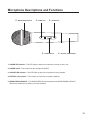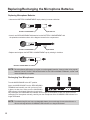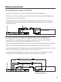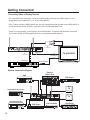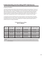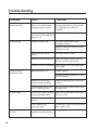
1
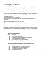
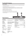
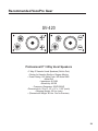
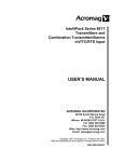
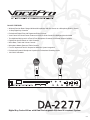
DA-2277 FEATURES:
• Wireless Receiver Base Charges Wireless Microphones and Also Serves as a Microphone Docking Station
• 11-Step Digital Key Controller
• Professional Digital Echo with Repeat and Delay Controls
• Vocal Cancel and Vocal Partner Features to Remove Guide Vocals from Multiplex Karaoke Media
• Two Additional Mic Inputs for a Total of Four Microphone Channels w/ Individual Volume Controls
• Digital Echo On/Off Switch on 3 Mic Channels
• Music Bass, Treble and Volume Controls
• Microphone Master, Bass and Treble Controls
• Four A/V Inputs and Two A/V Outputs for Maximum System Integration
• Professional Dynamic Microphone Capsules for Professional Sounding Vocals
• 110V-220V Switchable
Digital Key Control Mixer with/Dual Rechargeable Wireless Mic System
Delay
0
DIGITAL KEY CONTROLLER
POWER
Down
Normal
Up
0
Vocal Partner Vocal Cancel
A/V Source
Music
0
Repeat
10
0
Digital Echo
10
0
Mic 4
5
0
10
Mic Master
0
-15
+15
Bass
Mic 1
(wireless)
Mic 2
(wireless)
10
Echo On
9
Mic 3
Echo On
Echo On
0
-15
+15
Treble
Remote
Key Control
Mic 4 Input
Mic 3 Input
DA-2277
Digital Key Control Mixer with Dual Rechargeable Wireless Microphone System
v.1
DA-2277
Digital Key Control Mixer with Dual Rechargeable Wireless Microphone System
Contents
Cautions and Warnings . . . . . . . . . . . . . . . . . . . . . . . . . . . . . . . . . . . . . . . . . . . .
1-2
Welcome . . . . . . . . . . . . . . . . . . . . . . . . . . . . . . . . . . . . . . . . . . . . . . . . . . . . . . . .
3
Listening for a Lifetime . . . . . . . . . . . . . . . . . . . . . . . . . . . . . . . . . . . . . . . . . . . .
4
Features and Specifications . . . . . . . . . . . . . . . . . . . . . . . . . . . . . . . . . . . . . . . .
5
Before Getting Started . . . . . . . . . . . . . . . . . . . . . . . . . . . . . . . . . . . . . . . . . . . . .
6
Microphone Basics . . . . . . . . . . . . . . . . . . . . . . . . . . . . . . . . . . . . . . . . . . . . . . .
7-8
Front Panel Descriptions . . . . . . . . . . . . . . . . . . . . . . . . . . . . . . . . . . . . . . . . . . .
9
Front/Top Panel Descriptions . . . . . . . . . . . . . . . . . . . . . . . . . . . . . . . . . . . . . . .
10
Rear Panel Descriptions . . . . . . . . . . . . . . . . . . . . . . . . . . . . . . . . . . . . . . . . . . .
11
Microphone Descriptions . . . . . . . . . . . . . . . . . . . . . . . . . . . . . . . . . . . . . . . . . .
12
Replacing/Recharging the Microphone Batteries . . . . . . . . . . . . . . . . . . . . . . .
13
Getting Connected . . . . . . . . . . . . . . . . . . . . . . . . . . . . . . . . . . . . . . . . . . . . . . . . 14-15
Understanding and Avoiding VHF Interference. . . . . . . . . . . . . . . . . . . . . . . . . 16-18
Troubleshooting . . . . . . . . . . . . . . . . . . . . . . . . . . . . . . . . . . . . . . . . . . . . . . . . . .
19
Glossary of Terms . . . . . . . . . . . . . . . . . . . . . . . . . . . . . . . . . . . . . . . . . . . . . . . . 20-21
Recommended VocoPro Gear . . . . . . . . . . . . . . . . . . . . . . . . . . . . . . . . . . . . . . . 22-24
Safety Instructions
CAUTION
RISK OF SHOCK
CAUTION: To reduce the risk of electric shock,
do not remove cover (or back). No userserviceable parts inside. Only refer servicing to
qualified service personnel.
Explanation of Graphical Symbols
The lightning flash & arrowhead
symbol, within an equilateral triangle,
is intended to alert you to the
presence of danger.
The exclamation point within an
equilateral triangle is intended to alert
you to the presence of important
operating and servicing instructions.
WARNING
To reduce the risk of fire or electric shock, do
not expose this unit to rain or moisture.
8. Ventilation - The appliance should be situated so its
location does not interfere with its proper ventilation. For
example, the appliance should not be situated on a bed,
sofa, rug, or similar surface that may block the
ventilation slots.
9. Heat - The appliance should be situated away from
heat sources such as radiators, heat registers,
stoves, or other appliances (including amplifiers)
that produce heat.
10. Power Sources - The appliance should be
connected to a power supply only of the type described
in the operating instructions or as marked on the
appliance.
11. Grounding or Polarization – Precautions should be
taken so that the grounding or polarization means of
an appliance is not defeated.
12. Power-Cord Protection – Power-supply cords
should be routed so that they are not likely to be walked
on or pinched by items placed upon or against them,
paying particular attention to cords at plugs,
convenience receptacles, and the point where they exit
from the appliance.
13. Cleaning – Unplug this unit from the wall outlet
before cleaning. Do not use liquid cleaners or
aerosol cleaners. Use a damp cloth for cleaning.
14. Power lines – An outdoor antenna should be
located away from power lines.
1. Read Instructions - All the safety and operating
instructions should be read before the appliance is
operated.
15. Nonuse Periods – The power cord of the appliance
should be unplugged from the outlet when left unused
for a long period of time.
2. Retain Instructions - The safety and operating
instructions should be retained for future reference.
16. Object and Liquid Entry – Care should be taken so
that objects do not fall and liquids are not spilled into the
enclosure through openings.
3. Heed Warnings - All warnings on the appliance and in
the operating instructions should be adhered to.
4. Follow Instructions - All operating and use
instructions should be followed.
5. Attachments - Do not use attachments not
recommended by the product manufacturer as they may
cause hazards.
6. Water and Moisture - Do not use this unit near water.
For example, near a bathtub or in a wet basement and
the like.
7. Carts and Stands - The appliance should be used
only with a cart or stand that is recommended by the
manufacturer.
7 A. An appliance and cart combination
should be moved with care. Quick stops,
excessive force, and uneven surfaces may
cause an overturn.
1
17. Damage Requiring Service – The appliance should
be serviced by qualified service personnel when:
A.
B.
C.
D.
The power supply cord or plug has been damaged; or
Objects have fallen into the appliance; or
The appliance has been exposed to rain; or
The appliance does not appear to operate normally
or exhibits a marked change in performance; or
E. The appliance has been dropped, or the enclosure
damaged.
18. Servicing – The user should not attempt to service
the appliance beyond that described in the operating
instructions. All other servicing should be referred to
qualified service personnel.
CAUTION: Read this before operating your unit
CAUTION
The apparatus is not disconnected from the AC power source so long as it is connected to the
wall outlet, even if the apparatus itself is turned off. To fully insure that the apparatus is indeed
fully void if residual power, leave unit disconnected from the AC outlet for at least fifteen
seconds.
1. To ensure the finest performance, please read this manual carefully. Keep it in a safe place for future
reference.
2. Install your unit in a cool, dry, clean place – away from windows, heat sources, and too much vibration,
dust, moisture or cold. Avoid sources of hum (transformers, motors). To prevent fire or electrical shock, do
not expose to rain and water.
3. Do not operate the unit upside-down.
4. Never open the cabinet. If a foreign object drops into the set, contact your dealer.
5. Place the unit in a location with adequate air circulation. Do not interfere with its proper ventilation; this will
cause the internal temperature to rise and may result in a failure.
6. Do not use force on switches, knobs or cords. When moving the unit, first turn the unit off. Then gently
disconnect the power plug and the cords connecting to other equipment. Never pull the cord itself.
7. Do not attempt to clean the unit with chemical solvents: this might damage the finish. Use a clean,
dry cloth.
8. Be sure to read the “Troubleshooting” section on common operating errors before concluding that your unit
is faulty.
9. This unit consumes a fair amount of power even when the power switch is turned off. We recommend that
you unplug the power cord from the wall outlet if the unit is not going to be used for a long time. This will
save electricity and help prevent fire hazards. To disconnect the cord, pull it out by grasping the plug.
Never pull the cord itself.
10. To prevent lightning damage, pull out the power cord and remove the antenna cable during an electrical
storm.
11. The general digital signals may interfere with other equipment such as tuners or receivers. Move the
system farther away from such equipment if interference is observed.
12. When positioning your equipment, especially regarding speakers or other accessories, avoid positioning
them over areas where they can fall and cause injury to yourself and others.
2
Listening For A Lifetime
Selecting fine audio equipment such as the unit you’ve just purchased is only the start of
your musical enjoyment. Now it’s time to consider how you can maximize the fun and
excitement your equipment offers. VocoPro and the Electronic Industries Association’s
Consumer Electronics Group want you to get the most out of your equipment by playing it
at a safe level. One that lets the sound come through loud and clear without annoying
blaring or distortion and, most importantly, without affecting your sensitive hearing.
Sound can be deceiving. Over time your hearing “comfort level” adapts to a higher volume
of sound. So what sounds “normal” can actually be loud and harmful to your hearing. Guard
against this by setting your equipment at a safe level BEFORE your hearing adapts.
To establish a safe level:
• Start your volume control at a low setting.
• Slowly increase the sound until you can hear it comfortably and clearly, and without
distortion.
Once you have established a comfortable sound level:
• Set the dial and leave it there.
• Pay attention to the different levels in various recordings.
Taking a minute to do this now will help to prevent hearing damage or loss in the future.
After all, we want you listening for a lifetime.
Used wisely, your new sound equipment will provide a lifetime of fun and enjoyment. Since
hearing damage from loud noise is often undetectable until it is too late, this manufacturer
and the Electronic Industries Association’s Consumer Electronics Group recommend you
avoid prolonged exposure to excessive noise. This list of sound levels is included for your
protection.
Some common decibel ranges:
Level
Example
30
40
50
60
70
80
Quiet library, Soft whispers
Living room, Refrigerator, Bedroom away from traffic
Light traffic, Normal Conversation
Air Conditioner at 20 ft., Sewing machine
Vacuum cleaner, Hair dryer, Noisy Restaurant
Average city traffic, Garbage disposals, Alarm clock at 2 ft.
The following noises can be dangerous under constant exposure:
Level
Example
90
100
120
140
180
Subway, Motorcycle, Truck traffic, Lawn Mower
Garbage truck, Chainsaw, Pneumatics drill
Rock band concert in front of speakers
Gunshot blast, Jet plane
Rocket launching pad
-Information courtesy of the Deafness Research Foundation
4
The DA-2277 Features
DA-2277 FEATURES:
• Wireless Receiver Base Charges Wireless Microphones and Also Serves as a Microphone Docking Station
• 11-Step Digital Key Controller
• Professional Digital Echo with Repeat and Delay Controls
• Vocal Cancel and Vocal Partner Features to Remove Guide Vocals from Multiplex Karaoke Media
• Two Additional Mic Inputs for a Total of Four Microphone Channels w/ Individual Volume Controls
• Digital Echo On/Off Switch on 3 Mic Channels
• Music Bass, Treble and Volume Controls
• Microphone Master, Bass and Treble Controls
• Four A/V Inputs and Two A/V Outputs for Maximum System Integration
• Professional Dynamic Microphone Capsules for Professional Sounding Vocals
• 110V-220V Switchable
Digital Key Control Mixer with/Dual Rechargeable Wireless Mic System
Delay
0
DIGITAL KEY CONTROLLER
Specifications
Inputs Sensitivity:
MICS 3,4 (Wired)
STEREO AUDIO INPUT
POWER
Down
Normal
Up
0
Vocal Partner Vocal Cancel
A/V Source
Music
0
Repeat
10
0
Digital Echo
10
0
Mic 4
Echo On
9
5
0
10
Mic Master
0
-15
+15
Bass
Mic 3
Mic 1
(wireless)
Mic 2
(wireless)
10
Echo On
Echo On
0
-15
+15
Treble
Remote
Key Control
Mic 4 Input
Mic 3 Input
RECHARGEABLE VHF WIRELESS MICROPHONE:
1.5mV/1K ohms (1/4” Jack/Unbalanced)
50mV/10K ohms (RCA Jack)
Frequency Range: .................VHF frequency 180 to 250MHz.
Frequency Precision: .............±0.005¢M controlled by quartz.
Outputs:
AUDIO OUT 1
AUDIO OUT 2
AUDIO OUT 3
MIC OUTPUT
MAXIMUM OUTPUT
Modulation: ...................................................................FM type
0.75V/600 ohms (RCA Jack/Unbalanced)
0.75V/600 ohms (RCA Jack/Unbalanced) Maximum Deviation: ....................................................±15KHz
0.75V/600 ohms (XLR Jack/Balanced)
Frequency Response: ...................................100Hz to 13KHz
-56mV(1/4”/Unbalanced)
Signal/Noise Ratio: ...................................................over 80dB
+20dBV (8.5Vrms), 0dBV=1V
Operation Scope: ........................Radius 166' ( in free space )
Tone Controls:
TREBLE (10KHz)
BASS (100Hz)
Muting Type: .....TONE-Squelch coding lock still sound design
±15dB (STEREO), ±2dB
±15dB (STEREO), ±2dB
Receiving Sensitivity: .................................................10dB/uV
De-emphasis: .....................................................................50uS
Signal to Noise Ratio:
MIC
STEREO
>91dB (Below Max.)
>97dB (Below Max.)
Total Harmonic Distortion: 0.07% (STEREO)
+0.1% (MIC)
0Hz~20KHz ±3dB
Frequency Response:
Echo:
Key:
Dimensions:
Net Weight:
Power Consumption:
5
up to 300mS
9 steps up & down 1 octave
19” (W) x 9.5” (D) x 3.5” (H)
10.6 Lbs.
10W
Harmonic Interfering Ratio: .....................................over 80dB
Before Getting Started: Things to Consider
It is very important to read the following instructions prior to starting any installation
procedures. Doing so will ensure a correct installation and may save you some time as well.
Protect Against Power Surges
• Connect all external components before you plug any of their power cords into the
wall outlet.
• Turn off the DA-2277 before you connect or disconnect any cables.
• Make sure all cables are properly grounded.
Protect Components from Overheating
• Don’t block ventilation holes. Arrange any components so that air can circulate freely.
• Don’t stack components.
• If you place the DA-2277 on a stand, make sure you allow adequate ventilation.
Position Cables Properly to Avoid Audio Interference
• Insert each cable firmly into the designated jack.
• If you place components above the DA-2277, route all cables down the side of the
back of the DA-2277 instead of straight down the middle of the back of the
DA-2277.
Important Stand and Base Safety Information
Choose the location for your DA-2277 carefully. If the DA-2277 is placed on a stand or
base, ensure that it is of adequate size and strength to prevent it from being accidentally
tipped over, pushed off, or pulled off. This could cause personal injury and/or damage to the
DA-2277.
Unpacking the DA-2277
First carefully unpack all of the box contents. You should
have found the following items with your new DA-2277:
1 DA-2277 Receiver
2 Wireless Microphone Transmitters
2 RCA A/V Patch Cables
1 Four-Pack of AA Rechargeable Batteries
2 Mounting Brackets
7 Mounting Bracket Screws
Delay
Digital Key Control Mixer with/Dual Rechargeable Wireless Mic System
DIGITAL KEY CONTROLLER
POWER
Down
Normal
Up
0
Vocal Partner Vocal Cancel
A/V Source
Repeat
Digital Echo
Mic 4
Mic 3
0
Music
9
0
10
0
10
0
Echo On
5
0
10
Mic Master
0
-15
+15
Bass
Mic 1
(wireless)
Mic 2
(wireless)
10
Echo On
0
-15
+15
Treble
Echo On
Remote
Key Control
Mic 4 Input
Mic 3 Input
6
Microphone Basics
Wireless Microphones - The Basics
• Every wireless microphone system must operate on a specific frequency range.
• The government dictates the frequency ranges available for use with consumer wireless devices.
• Wireless frequencies are shared with TV stations, communications equipment and a large number of wireless
microphone systems.
• Because of frequency sharing, there is always at least a small chance that someone else in the area might be
using the same frequency as your wireless system.
• There must be one transmitter and one receiver to make a complete wireless system, and they both must be on
the same frequency.
• If the frequencies of any two wireless systems are too close together, interference is likely, and one or both
systems will probably be compromised.
• The practical maximum operating range of a wireless system will vary from as little as 100 feet (30 m) in heavily
crowded indoor situations to 150 feet (40 m) In low crowded situation.
• Wireless receivers must have either one or two external antennas, and there should be a clear open-air path
between these antennas and the transmitter.
• Weak or worn-out transmitter batteries are a common cause of wireless problems, including complete failure,
poor range, distorted audio and interference.
Microphone Position
The DA-2277 wireless microphones are ideal for close-up vocals and can be held in the hand or mounted on a
microphone stand. The most common applications and placement techniques are listed below. Keep in mind that
microphone technique is largely a matter of personal taste—there is no one "correct" microphone position.
Lead & Backup Vocals
Lips should be less than 3" from or even touching the windscreen on an axis to the microphone. Doing this
creates a robust sound, emphasizes bass and provides maximum isolation from other sources.
Speech
When giving a speech or simply speaking, place the microphone 4" to 10" away from the mouth, just above nose
height for a natural sound with reduced bass. You can also place the microphone 8" to 16" away from the mouth,
slightly off to one side, for a more "distant" sound with highly reduced bass and minimal "s" sounds.
Proximity Effect
When the sound source is less than 1/4 in. from the microphone, the microphone boosts bass frequencies
(by 6 to 10 dB at 100 Hz), creating a warmer and richer bass sound than when farther away. This effect, known
as proximity effect, happens only in unidirectional dynamic microphones like those used with the DA-2277.
7
Microphone Basics
Avoiding Feedback
Acoustic feedback can be a problem in any sound system. Audio systems that include wireless microphones are
somewhat more prone to feedback than those using only wired microphones, simply because the freedom of
movement with wireless makes it more likely that the user will walk in front of the speakers. Take steps to make it
less likely that the wireless user will walk in front of the speakers. These steps can include more rehearsal time,
markings on the floor, relocation of the speakers and several other options.
More Tips to Avoid Interference
• Lower the sound level of the speakers nearest the wireless user and increase the level of other speakers to
compensate. If possible, rotate the nearest speakers to point them slightly away from the wireless user.
• Make certain that the transmitter gain is set appropriately for your application. If the transmitter gain is set too
high, it may cause overloading of the wireless circuits and increase the chances of feedback.
• Most standard techniques for reducing feedback will also work with wireless microphones. Because of the
increased chance of feedback with wireless, understanding and being able to apply these techniques will
be helpful.
• Request that the talker speak louder into the microphone so microphone levels can be reduced.
• Reduce the distance from the talker to the microphone.
• Reduce the number of open microphones. Each time this number is halved, the sound system output can be
increased by 3dB.
• Move the loudspeaker farther away from the microphone.
• Move the loudspeaker closer to the listener.
• Use an equalizer/feedback reducer to cut the frequency bands in which the feedback occurs.
DA-2277 & Stage Monitors/P.A. System
• Place the stage monitor directly behind the microphone.
• Locate the P.A. loudspeakers so that they point away from the rear of the microphone.
(With the speakers located in these positions, the possibility of feedback is greatly reduced).
• Always check the stage setup before a performance to ensure optimum placement of microphone and monitors.
IMPORTANT: Every wireless microphone installation is a unique situation, and can present a variety of problems.
Never attempt a live performance without first conducting a "walk through" test of the system in the performing area.
If major changes (additional wireless systems or intercoms, relocation of scenery, etc.) have been made since the
last walk–through test, check the wireless system again—as close to performance time as possible.
8
Front Panel Descriptions and Controls
1
2
3
4
5
6
7
Digital Key Control Mixer with/Dual Rechargeable Wireless Mic System
Delay
0
DIGITAL KEY CONTROLLER
POWER
Down
Normal
Up
0
Vocal Partner Vocal Cancel
A/V Source
Music
0
Repeat
10
0
Digital Echo
10
0
Mic 4
Echo On
9
5
0
10
Mic Master
0
-15
+15
Bass
Mic 3
Mic 1
(wireless)
Mic 2
(wireless)
10
Echo On
Echo On
0
-15
+15
Treble
Remote
Key Control
Mic 4 Input
Mic 3 Input
1. POWER button –This button turns the DA-2277’s power ON/OFF.
2. DOWN, NORMAL AND UP buttons – These buttons adjusts how the DIGITAL KEY CONTROLLER
transposes the musical key of your source music. The DOWN button lowers the MUSICAL
KEY a half step each time it is pressed. The NORMAL key resets the MUSICAL KEY back to it’s original key
and the UP button raises the MUSICAL KEY a half step each time it is pressed.
3. VOCAL CANCEL AND VOCAL PARTNER buttons – These buttons activate the MULTIPLEX audio
playback modes that are used to cancel out the guide vocals from multiplexed karaoke
media. During playback of a multiplexed track, press the VOCAL CANCEL button once to remove the guide
vocals. Press the VOCAL CANCEL button a second time to have the guide vocals return to playback.
VOCAL PARTNER also cancels out the guide vocals from multiplexed karaoke media, however the guide
vocals are only removed as long as you are singing into the microphone. When you stop singing into the
microphone, the guide vocals are reintroduced automatically. Press the VOCAL PARTNER once to initialize
the feature, and press a second time to disable the feature.
NOTE: Attempting to utilize this feature with a non-multiplexed track will not work as this
feature is designed to work with multiplexed tracks only.
4. A/V SOURCE button –This button toggles input between devices that may be connected to the CDG and
DVD A/V channels. For input from the CDG channel, press the A/V SOURCE button once.
For input from the DVD channel, press the A/V SOURCE button a second time.
5. LEVEL meters – These LED meters display the overall output level from both the A/V SOURCE and
MICROPHONE channels. When there is red LED activity, the output level is in or nearing a distorted level
and should be monitored carefully if not reduced.
6. MUSIC BASS, TREBLE AND MASTER controls – These controls adjust the BASS, TREBLE and
MASTER VOLUME levels for your source music. The BASS and TREBLE controls adjust the low and high
frequency levels for your source music, while the MASTER control adjusts the overall volume level of your
source music.
NOTE: Microphone output is not affected by adjustments made to these controls.
7. MIC MASTER control – The MIC MASTER control adjusts the overall volume of all microphone output.
NOTE: If you need to adjust the volume level of just one MIC channel in particular, use that MIC’s individual
volume level control instead of the MIC MASTER control.
9
Front/Top Panel Descriptions and Controls
TOP VIEW OF DA-2277
8
14
Digital Key Control Mixer with/Dual Rechargeable Wireless Mic System
Delay
0
DIGITAL KEY CONTROLLER
POWER
Down
Normal
Up
0
Vocal Partner Vocal Cancel
A/V Source
Music
0
Repeat
10
0
12
Digital Echo
10
0
Mic 4
Echo On
9
5
0
0
10
Mic Master Volume
-15
+15
Bass
Mic 3
(wireless)
Echo On
Mic 2
(wireless)
Echo On
0
-15
+15
Treble
Remote
Key Control
Mic 4 Input
Mic 3 Input
11
9
Mic 1
10
13
10
8. MIC BASS AND TREBLE controls – These controls adjust the low and high frequency levels for all
microphone output. turn clockwise to increase and counter- clockwise to decrease.
9. DIGITAL ECHO, REPEAT AND DELAY controls –The DIGITAL ECHO, REPEAT and DELAY controls
adjust the DA-2277’s processing of DIGITAL ECHO. The DIGITAL ECHO, DELAY and REPEAT knobs will
alter the levels of effects on all 3 Mic channels simultaneously. The DIGITAL ECHO knob controls the
overall echo applied to the 3 Mic channels, the DELAY knob controls the interval time between each echo
and the REPEAT knob controls the # of times the echo will repeat. For all 3 effects knobs, turn clockwise
to increase and counter- clockwise to decrease.
10. MIC 3 AND 4 jacks- These 1⁄4 inch input jacks are for connecting microphones or instruments.
11. REMOTE KEY CONTROL jack – This jack is for connecting the 1/8" plug found on a key controllable
microphone. After plugging the in the microphone, you can control the DIGITAL KEY CONTROLLER with
the key controls located on the microphone.
12. MIC 1, 2, 3 AND 4 LEVEL controls –These knobs control the MIC CHANNELS output levels
individually. This makes it possible to adjust just one Mic channel without affecting the other 3 channels.
This can be useful when one person or (Mic channel) might be overpowering others in a duo or trio. Turn
clockwise to increase output levels, and counter-clockwise to decrease output levels.
13. DIGITAL ECHO ON/OFF button – Microphone channels 1, 3 and 4 have one of these buttons.
By pressing it, you activate the DIGITAL ECHO for that channel. By depressing it, you remove the
DIGITAL ECHO from that channel.
NOTE: Microphone channel 2 does not have an ECHO ON/OFF switch as that channel is used as a "dry"
(no echo) microphone channel.
14. MICROPHONE CHARGING terminals – These terminals are for charging the microphones when they
are not in use. Place microphone in the terminal and twist it clockwise till it "clicks" into position.
10
Rear Panel Descriptions and Controls
1
2
4
LA VERNE, CALIFORNIA USA
3
3/L
BALANCED OUT
4
3/R
2
5
1
A4/VCD
A3/LD
A2/CDG
6
V3/LD
A1/DVD
V1/DVD
7
1
9
SERIAL NUMBER
MIC OUT ONLY
VIDEO
IN
VIDEO
OUT
ANT 2
www.vocopro.com
AUDIO OUT
VIDEO IN
V4/VCV
V2/CDG
!
CAUTION
RISK OF ELECTRICAL SHOCK
DO NOT OPEN
CAUTION: TO PREVENT ELECTRIC SHOCK,
DO NOT REMOVE COVER SCREWS
NO USER-SERVICEABLE PARTS INSIDE.
REFER SERVICING TO QUALIFIED
PERSONNEL
115
ANT 1
8
WARNING: TO REDUCE THE RISK OF
FIRE OR ELECTRICAL SHOCK
DO NOT EXPOSE THIS EQUIPMENT
TO RAIN OR MOISTURE
AC OUTPUT
2
1. ANTENNA 1 jack – Connect a RECEIVER ANTENNA to this jack before attempting to use this device.
Ensure the ANTENNA is fully extended for optimal signal reception.
2. MIC OUT jack (1/4") – This jack provides an AUDIO OUT connection of MICROPHONE OUTPUT only for
vocal specific applications (vocal effects). No A/V source music will output from this jack. Connect a 1⁄4"
audio patch cable from this jack to the AUDIO IN jacks on your external device.
3. AUDIO OUT jacks (XLR) – These jacks are for connecting balanced AUDIO OUTPUT from the DA-2277
to external amplifiers, mixers or recording devices. Connect a pair of XLR cables from these jacks to the
AUDIO IN jacks on your external amplifier, mixer or recording device.
4. AUDIO OUT 1 AND 2 jacks (RCA) – These jacks are for connecting unbalanced AUDIO OUTPUT from the
DA-2277 to external amplifiers, mixers or recording devices. Connect a paired RCA patch cable from these
jacks to the AUDIO IN jacks on your external amplifier, mixer or recording device. Up to 2 devices can be
connected to these AUDIO OUT jacks.
5. A/V AUDIO IN jacks (RCA) – These jacks are for connecting AUDIO from your A/V source players.
Connect a paired RCA patch cable from these jacks to the AUDIO OUT jacks on your A/V source player.
Up to 4 A/V source players can be connected.
6. VIDEO IN jacks (RCA) – These jacks are for connecting VIDEO from your A/V source players. Connect an
RCA patch cable from these jacks to the VIDEO OUT jacks on your A/V source players. Ensure that the
VIDEO IN jacks correspond with the player connected to the AUDIO IN jacks.
7. VIDEO OUT jacks (RCA) – These jacks route the VIDEO signals from the DA-2277 to your TV or display
devices. Connect an RCA patch cable from these jacks to the VIDEO IN jack on your TV or display device.
Up to 2 display devices can be connected to these jacks.
8. ANTENNA 2 jack – Connect a RECEIVER ANTENNA to this jack before attempting to use this device.
Ensure the ANTENNA is fully extended for optimal signal reception.
9. VOLTAGE selector – Selects between 115V and 230V power supply settings. Select 110V for North
American based power requirements and 230V for European based power requirements.
NOTE: It is imperative that this setting is set correctly before powering on your DA-2277.
11
Microphone Descriptions and Functions
5.
WINDSCREEN/CAPSULE
1.
POWER LED
2.
3.
CHARGE LED
POWER SWITCH
4.
BATTERY COMPARTMENT
1. POWER LED indicator – This LED lights up when the microphone is turned on and in use.
2. POWER switch – This switch turns the microphone ON/OFF.
3. CHARGE LED indicator – This LED lights up when the microphone is being charged.
4. BATTERY compartment – This is where you insert the microphone batteries.
5. WINDSCREEN/CAPSULE – The WINDSCREEN houses and protects the MICROPHONE CAPSULE.
Remove the windscreen by twisting it counter-clockwise.
12
Replacing/Recharging the Microphone Batteries
Replacing Microphone Batteries
• Unscrew the BATTERY COMPARTMENT cap by twisting it counter-clockwise.
BATTERY COMPARTMENT
BATTERY LID
• Insert 2 new RECHARGEABLE AA batteries into the BATTERY COMPARTMENT with
the polarities matched as shown in the diagram located in the compartment.
BATTERY COMPARTMENT
BATTERIES
• Replace and retighten the BATTERY COMPARTMENT cap by twisting it clockwise.
BATTERY COMPARTMENT CLOSED
NOTE: The microphones will operate on regular non-rechargeable batteries, however when using regular
batteries, DO NOT PLACE THE MICROPHONE IN THE RECHARGING TERMINAL, as that could
cause the batteries to explode.
Recharging Your Microphones
Turn the MICROPHONE to the OFF position.
Insert the MICROPHONE into the RECHARGING
TERMINAL and carefully turn it till you hear it "lock"
in place. At that time, make sure the CHARGING
LED indicator is illuminated. When the microphone is
fully recharged, the CHARGING LED indicator will no longer be illuminated. In case you need to end the
recharging of a microphone manually, carefully turn the microphone till the CHARGING LED indicator is no
longer illuminated.
Digital Key Control Mixer with/Dual Rechargeable Wireless Mic System
Delay
0
DIGITAL KEY CONTROLLER
POWER
Down
Normal
Up
0
Vocal Partner Vocal Cancel
Music
0
Repeat
10
0
Digital Echo
10
0
Mic 4
A/V Source
5
0
10
Mic Master
0
-15
+15
Bass
Mic 3
Echo On
13
(wireless)
Mic 2
(wireless)
Echo On
0
-15
+15
Treble
Remote
Key Control
Mic 4 Input
Mic 3 Input
NOTE: To maintain long-life use from a rechargeable battery, do not recharge for more than 8 hours or
allow to recharge after the CHARGING LED indicator is no longer illuminated.
Mic 1
10
Echo On
9
Getting Connected
Connecting A/V Source Players to the DA-2277
For each A/V source player, you will need an A/V patch cable (red, white and yellow plugs).
• Connect one set of red and white plugs to the AUDIO OUT jacks on your source player and the yellow plug to
the VIDEO OUT jack on your source player.
• Connect the other set of red and white plugs to an AUDIO IN jacks of your choice (VCD, LD, CDG, DVD)
on the DA-2277 and connect the yellow plug to the VIDEO IN jack corresponding to the same channel you
connected the audio to.
SOURCE PLAYER
4
LA VERNE, CALIFORNIA USA
3/L
BALANCED OUT
3/R
AUDIO OUT
2
1
A4/VCD
A3/LD
A2/CDG
V3/LD
A1/DVD
V1/DVD
1
VIDEO
IN
ANT 1
ANT 1
AUDIO OUT
V4/VCV
AUDIO IN
V2/CDG
!
VIDEO OUT
CAUTION
RISK OF ELECTRICAL SHOCK
DO NOT OPEN
CAUTION: TO PREVENT ELECTRIC SHOCK,
DO NOT REMOVE COVER SCREWS
NO USER-SERVICEABLE PARTS INSIDE.
REFER SERVICING TO QUALIFIED
PERSONNEL
VIDEO
OUT
www.vocopro.com
115
ANT2
SERIAL NUMBER
MIC OUT ONLY
WARNING: TO REDUCE THE RISK OF
FIRE OR ELECTRICAL SHOCK
DO NOT EXPOSE THIS EQUIPMENT
TO RAIN OR MOISTURE
AC OUTPUT
2
Connecting Audio Output to External Amplifiers, Mixers or Recording Devices
• For AUDIO OUTPUT connections, there are 4 possible connections that can be made simultaneously:
unbalanced RCA (x2), balanced XLR (x1) and isolated microphone 1⁄4" (x1).
• For each unbalanced RCA AUDIO OUTPUT connection, connect a paired RCA patch cable from the AUDIO IN,
LINE IN or CH. A-B jacks on your external devices to the AUDIO OUT jacks (1) or (2) on the DA-2277.
• For a balanced AUDIO OUTPUT connection, connect XLR audio cables from the AUDIO IN, LINE IN or CH. A-B
jacks on your external device to the AUDIO OUT jacks (3/L-3/R) on the DA-2277.
• For an isolated MICROPHONE OUTPUT connection, connect a 1⁄4" audio patch cable from the AUDIO IN
or LINE IN jacks on your external device to the (4) MIC ONLY –56dBv jack on the DA-2277.
MIC OUTPUT CONNECTION
XLR CONNECTION
RCA CONNECTION
4
LA VERNE, CALIFORNIA USA
3/L
BALANCED OUT
3/R
AUDIO IN
2
1
A4/VCD
A3/LD
A2/CDG
V3/LD
A1/DVD
V1/DVD
1
VIDEO
IN
ANT 1
ANT 1
www.vocopro.com
AUDIO OUT
AUDIO IN
V4/VCV
V2/CDG
!
BALANCED IN
AUDIO IN
CAUTION
RISK OF ELECTRICAL SHOCK
DO NOT OPEN
CAUTION: TO PREVENT ELECTRIC SHOCK,
DO NOT REMOVE COVER SCREWS
NO USER-SERVICEABLE PARTS INSIDE.
REFER SERVICING TO QUALIFIED
PERSONNEL
VIDEO
OUT
115
ANT2
SERIAL NUMBER
MIC OUT ONLY
WARNING: TO REDUCE THE RISK OF
FIRE OR ELECTRICAL SHOCK
DO NOT EXPOSE THIS EQUIPMENT
TO RAIN OR MOISTURE
AC OUTPUT
2
AMPLIFIER/MIXER
RECORDING DEVICE
14
Getting Connected
Connecting Video to Display Devices
• For each VIDEO OUT connection, connect a single RCA patch cable from the VIDEO IN jack on your
display device to the VIDEO OUT (1 or 2) jack on the DA-2277.
• If the TV does not have a VIDEO INPUT jack you may connect that end of the cable to the VIDEO INPUT of
a VCR and connect the RF OUTPUT of the VCR to the TV ANTENNA INPUT jack.
• If there is no VCR present, you will need to use an RF Modulator. To obtain an RF Modulator, check with
your VocoPro dealer. An RF Modulator can also be purchased from Radio Shack™.
OR
4
LA VERNE, CALIFORNIA USA
3/L
BALANCED OUT
3/R
2
1
A4/VCD
A3/LD
A2/CDG
V3/LD
A1/DVD
V1/DVD
1
VIDEO
IN
ANT 1
!
ANT 1
www.vocopro.com
AUDIO OUT
AUDIO IN
V4/VCV
V2/CDG
RF MODULATOR
CAUTION
RISK OF ELECTRICAL SHOCK
DO NOT OPEN
CAUTION: TO PREVENT ELECTRIC SHOCK,
DO NOT REMOVE COVER SCREWS
NO USER-SERVICEABLE PARTS INSIDE.
REFER SERVICING TO QUALIFIED
PERSONNEL
VIDEO
OUT
115
ANT2
SERIAL NUMBER
MIC OUT ONLY
WARNING: TO REDUCE THE RISK OF
FIRE OR ELECTRICAL SHOCK
DO NOT EXPOSE THIS EQUIPMENT
TO RAIN OR MOISTURE
AC OUTPUT
2
VIDEO OUT
OR
TV/MONITOR
VCR CONNECTION
TO VIDEO IN
TO VIDEO IN
VIDEO/ANT OUT
VCR
System Connection Diagram
External
Effects Unit
AMP
(BALANCE)
(BALANCE)
(BALANCE)
(BALANCE)
(BALANCE)
L
L
R
MIC 1
MIC 2
5
MIC 3
5
Gain
A/V1
VIDEO SEL.
5
Gain
(UNBALANCE)
A/V2
R
PHONO 2
A/V2
0
A/V3
CD
MASTER L
MASTER R
MASTER
POWER
RECORD
A/V3
0
PHONES
DVD Player
5
1
Gain
Light (DC 12V)
L
R
PHONO 1
A/V1
(BALANCE)
L
R
MIC 4
5
Gain
CUE
Level
LEFT
2
3
10
0
0
10
0
0
Treble
10
0
0
Treble
MASTER
10
PHONO 1
0
10
PHONO 2
0
10
0
CD
0
10
0
Treble
5
Treble
4
3
2
L
L
0
1
60
1
2
3
4
250
1K
10
4K
12K
5
12
12
12
12
12
6
6
6
6
6
0
0
0
0
VU METER
AUTO
b
OFF
-15
+15
-15
0
+15
+15
+15
-15
0
Bass
-15
-15
0
Bass
-15
+15
+15
ON
0
Bass
-15
+15
-15
+15
10
5
5
Echo
5
Echo
10
5
Echo
#
DIGITAL KEY CONTROLLER
VOCAL CANCEL
Bass
8
CUE
8
RIGHT
0
Graphic Equalizer
10
CUE
Echo
CUE
VU METER
EQUALIZER
8
ON
6
0
10
0
10
0
10
0
10
10
CUE
8
10
CUE
8
6
CUE
8
6
CUE
8
6
KEY
4
ON
KEY
KEY
4
4
4
2
2
2
2
0
0
0
0
MIC 2
MIC 3
10
10
10
8
8
8
6
6
6
4
4
4
2
2
2
0
0
0
5
ECHO
MASTER L
MASTER R
2
0
A/V1
ON
KEY
4
2
0
0
0
A/V2
10
5
REPEAT
A/V3
0
1
MIC 1
6
KEY
4
2
AUTO
OFF
6
KEY
4
6
KEY
10
TALK OVER
10
ECHO
MIC 4
2
2
CROSSFADER
ASSIGN
10
5
DELAY
4
0
BOOTH
10
Digital
Echo
ASSIGN
TV
Vocal Effects Processor
4
LA VERNE, CALIFORNIA USA
3/L
BALANCED OUT
3/R
2
1
A4/VCD
A3/LD
A2/CDG
V3/LD
A1/DVD
V1/DVD
1
SERIAL NUMBER
MIC OUT ONLY
!
CAUTION
RISK OF ELECTRICAL SHOCK
DO NOT OPEN
CAUTION: TO PREVENT ELECTRIC SHOCK,
DO NOT REMOVE COVER SCREWS
NO USER-SERVICEABLE PARTS INSIDE.
REFER SERVICING TO QUALIFIED
VIDEO
IN
ANT 1
PERSONNEL
ANT 1
www.vocopro.com
AUDIO OUT
AUDIO IN
V4/VCV
V2/CDG
115
ANT2
VIDEO
OUT
WARNING: TO REDUCE THE RISK OF
FIRE OR ELECTRICAL SHOCK
DO NOT EXPOSE THIS EQUIPMENT
TO RAIN OR MOISTURE
2
AC OUTPUT
TV
Recording Device
VCD Player
15
CD/LD PLAYER
CDG Player
Understanding and Avoiding VHF Interference
Recognizing Interference
The ways of recognizing the type of interference present are observing the receiver LED indications and
carefully listening to the audio. A set of headphones can be a useful tool in isolating and analyzing
interference problems. With headphones it is easier to listen to one wireless channel at a time, even when the
system is in use.
Below are some interference descriptions. Most likely there is one that matches the symptoms that you are
experiencing.
• If there is interference when the microphones are off, and noise/distortion is present from the receiver output
when the microphones are on, try turning off all other wireless microphones.
If the interference problem is still present, there might be a direct radio interference problem.
Direct interference is a serious problem that must be corrected in order for the wireless system to be
fully usable.
• Interference in the form of low level-audio tones, whines, whining sounds whose pitch changes rapidly,
or audible voices or music (distorted or not) is likely to be caused by intermodulation, non-wireless
interference or direct interference.
• If there is interference when the receiver is turned on, in the form of buzzy or raspy whines with a distinct
cadence or rhythm that differs from time to time, digital interference might be the problem.
Common sources include computers, digital delays, effects processors, lighting controllers, and other digital
equipment using microprocessors and digital signal processors (DSPs).
• If there is no interference when the receiver is turned off and irregular popping, cracking or buzzing noises
on the audio with the receiver on, there may be electrical interference problems. This kind of interference is
usually caused by electric motors, neon lights, lighting equipment, appliances and other types of electrical
equipment. Electrical interference will generally affect all wireless systems at a location, not just one system.
• Certain types of buzzing sounds are actually due to interference from TV stations. If the buzzing sound
changes substantially at more or less random intervals and does not seem to be caused by electrical
equipment, the problem may be TV interference.
• Interference that takes the form of bursts of static or short bursts of noise is likely to be caused by lightning,
intermittent arcing or defective electrical machinery. This type of random interference is pretty rare but can be
among the most difficult to resolve.
16
Understanding and Avoiding VHF Interference
Avoiding Basic Problems
Sometimes interference problems have very basic causes. To avoid wasting time on an easily correctable
problem, check the following items before proceeding:
• Make certain than no radio transmitters are allowed to come closer than approximately 10 to 15 feet of the
wireless receiver antennas. This can overload the receiver and increase the chances of interference.
• Make certain not to allow receiver antennas to touch each other when arranging them.
Be sure that the antennas from one receiver do not touch, or come too close to, those of another receiver.
Try to provide at least 10 inches of separation between the antennas of any two receivers.
• Make sure that all microphones have charged batteries. The low output voltage of weak batteries can cause
some microphones to generate harmful interference. If there is any doubt, install fresh batteries in
all microphones.
• Make sure that the wireless frequencies are not on a local TV channel.
• Check the wireless frequencies in use to make sure that no two systems are on the same frequency.
• Check to make sure that no two wireless frequencies are too close together. In general, 1 MHz is the
recommended minimum spacing between systems.
• If a considerable number of systems will be used, operating conditions will be difficult or interference is likely,
if possible avoid these situations.
• Before using a system in a new location or another city, double-check for new problems.
Small changes in conditions can cause interference where none was present before.
• Turn off unnecessary electronic equipment, especially computers and digital devices.
These are a relatively common cause of wireless interference.
• If use of computers or digital devices is necessary, keep them at least 18 inches
(45 cm) away from the microphones and receiver antennas.
17
Understanding and Avoiding VHF Interference
Frequency Conflicts
There are two primary ways that other wireless systems and TV channels cause interference. The first is a
direct frequency conflict. If two wireless systems are on the same frequency, usually neither system will be
usable unless the other is turned off. This problem is more common than might be expected, especially
when all the equipment is the same type. This is because most systems have only a limited number of
standard frequencies. It should be remembered that the other systems could be some distance away - in
another house of worship down the street, in another nearby studio, or at another club in the vicinity.
TV transmitters can also be a powerful source of direct interference if the wireless frequency falls within
the assigned channel of a local TV station. This problem sometimes occurs because wireless frequencies
are listed in MHz and it is not always obvious within which TV channel a particular frequency falls. For
reference, below is TV frequency information.
TV Channel Frequency Data
VHF TV Channels
Channel
Number
Frequency
Range (MHz)
Picture Carrier
Frequency (MHz)
Color Sub carrier
Frequency (MHz)
Sound Sub carrier
Frequency (MHz)
7
8
9
10
174-180
180-186
186-192
192-198
175.250
181.250
187.250
193.250
178.8295
184.8295
190.8295
196.8295
179.750
185.750
191.750
197.750
11
12
198-204
204-210
199.250
205.250
202.8295
208.8295
203.750
209.750
13
210-216
211.250
214.8295
215.750
NOTE: The low VHF TV channels (2 through 6) are not used for wireless microphones and do not need
to be considered
18
Troubleshooting
PROBLEMS
Battery is running low even
when just charged.
CAUSE
SOLUTIONS
The microphone is not recharging Reinsert the microphone into the
because it is not placed in the
recharging terminal and gently turn it till
recharging terminal correctly.
the CHARGING LED indicator is
illuminated.
Battery is not fully recharged
Replace with new rechargeable batteries.
after 8 hours of recharging due to
it being too old.
No sound output.
Microphone output is low.
Turn up the output level for each
microphone channel.
Adjust the output level selector for each
microphone to high.
Master volume is turned to
minimum.
Turn up the master volume
External devices not functioning.
Inspect and replace external devices if
they are not functioning correctly.
Red LED is lit on the microphone Place microphone in a recharging station
till recharged.
Excessive noise in
microphone output.
Batteries/charge are low.
Replace batteries
Recharge microphone batteries or replace
with new batteries.
No music output.
No echo is being applied to
the vocals
19
Antennas are not receiving
microphone signals optimally.
Extend the antennas to their outer most
positions.
The microphones are out of the
DA-2277’s operating range.
Move closer to the receiver till you are in
operating range.
The A/V source selector is set to
the wrong operating channel.
Set the A/V source selector to the current
active A/V source.
The master volume is set to a
minimum
Turn up the master volume.
The A/V cables are not
connected properly.
Reconnect A/V cables correctly and firmly
making good contact.
The echo on/off button for the
microphone channels are set to
off.
Set the echo on/off buttons to ON.
Glossary of Terms
Digital Echo - Digital echo is a synthetically processed sound effect that mimics natural echo. Echo in general
is the "bouncing" of waves back and forth between 2 surfaces. This effect gives a spacious or ambient feeling
that works great with vocals.
Repeat - Repeat is facet of the echo process. Repeat refers to the frequency of echoes within a period of time.
Delay - Delay is also a facet of the echo process. Delay refers to the amount of time that exists between
echoes.
Vocal Cancel - Vocal Cancel is a feature that removes vocals from multiplex CD tracks. To be multiplexed, a
disc must have the vocals coded to the right channel and the music coded to the left channel. When you
select Vocal Cancel, the unit will remove the right channel (vocals) and split the left channel (music) to both
sides.
Vocal Partner - Vocal Partner is a feature that removes vocals from multiplex CD tracks much in the same
way as Vocal Cancel, but with an added "auto-pilot" function. The main difference is that Vocal Partner will
only remove vocals as long as there is activity going through the microphone (singing). When you stop
singing, the vocals automatically return.
Vocal Reducer - Vocal Reducer is a feature that removes vocals from standard non-multiplex CD tracks. To
do this, the unit compares the audio on the left and right channels, and cancels out any signals that appear on
both. Most currently recorded CD’s contain the vocal layer on both sides, however some may not, leading to
varying results.
CD+G or CDG - A CD+G is a specially formatted disc that has an additional line of sub-code on the CD that is
responsible for the lyrics that play on video screen for Karaoke systems. CD+G stands for Compact Disc +
Graphics.
Sub-Code - Sub-code is specially coded area of data used by CD+G manufacturers to produce lyrics for
Karaoke video output.
Multiplex (MPX) - Multiplex is a type of Karaoke software that has specially formatted left and right channels
to make multiplex features available. To be formatted for multiplex use, a disc must have the vocals coded to
the right channel and the music to the left channel. When you select a multiplex mode, the unit will remove the
right channel (vocals) and split the left channel (music) to both sides.
Rack Mountable - Rack Mountable refers to the ability to place unit into professional or travel rack cases.
Such cases are great for building complete systems and protect them during transportation. The standard
rack size for MOST cases is 19".
VCD - VCD is a disc formatted in MPEG-1. These discs are good candidates for Karaoke use as they have an
audio and a video layer to them. VCD stands for Video Compact Disc.
20
Glossary of Terms
A/V - A/V is an abbreviation for Audio/Visual.
Y-Adapter - Any type of connection that splits a signal into two parts. An example would be a connector with
one male RCA jack on one end, and two female RCA jacks on the other end.
Woofer - A speaker, (driver), used for low-frequency reproduction. Usually larger and heavier than a midrange
or tweeter.
Midrange - A speaker, (driver), used to reproduce the middle range of frequencies. A midrange is combined
with a woofer for low frequencies and a tweeter for high frequencies to form a complete, full-range system.
Tweeter - A speaker, (driver), used to reproduce the higher range of frequencies. To form a full-range system,
a tweeter needs to be combined with a woofer, (2-way system), or a woofer and midrange, (3-way system).
Pre-Amplifier - Or Pre-amp is a device that takes a source signal, such as from a turntable, tape-deck or CD
player, and passes this signal on to a power-amplifier(s). The pre-amp may have a number of controls such as
source selector switches, balance, volume and possibly tone-controls.
Out of Phase - When speakers are mounted in reverse polarity, i.e., one speaker is wired +/+ and -/- from the
amp and the other is wired +/- and -/+. Bass response will be very thin due to cancellation.
Line Level - CD players, VCRs, Laser disc Players etc., are connected in a system at line level, usually with
shielded RCA type interconnects. Line level is before power amplification. In a system with separate pre-amp
and power-amp the pre-amp output is line level. Many surround sound decoders and receivers have line level
outputs as well.
Frequency - The range of human hearing is commonly given as 20-20,000Hz (20Hz-20kHz). One hertz (Hz)
represents one cycle per second, 20Hz represents 20 cycles per second and so on. Lower numbers are lower
frequencies
Gain - To increase in level. The function of a volume control.
Decibel (dB) - Named after Alexander Graham Bell. We perceive differences in volume level in a logarithmic
manner. Our ears become less sensitive to sound as its intensity increases. Decibels are a logarithmic scale
of relative loudness. A difference of about 1 dB is the minimum perceptible change in volume, 3 dB is a
moderate change in volume, and about 10 dB is an apparent doubling of volume. 0 dB is the threshold of
hearing and 130 dB is the threshold of pain.
Clipping - Refers to a type of distortion that occurs when an amplifier is driven into an overload condition.
Usually the "clipped" waveform contains an excess of high-frequency energy. The sound becomes hard and
edgy. Hard clipping is the most frequent cause of "burned out" tweeters. Even a low-powered amplifier or
receiver driven into clipping can damage tweeters which would otherwise last virtually forever.
21
Recommended VocoPro Gear
CDG-4000 PRO
Professional CD/CD+ Graphic Player
• Pro CD Player W/ CD + Graphics Decoder
• Pitch Control To 12% (+) Or (-)
• Scramble protection during pitch changes
• Single Track Mode
• Frame Search W/ Jog Dial
• 4-Speed Fast Forward/Rewind Shuttle.
• Pitch Slider, Pitch Bend and Jog Dial
• BPM (Beat Per Minute) Synchronization
• Cue Detect Function
• Professional 19" Rack Mount Chassis
• Switchable 110-240V
• NTSC/PAL
• Dimensions: 19" W X 3 1/2" H X 10" D
• Shipping Weight: 9.35 Lbs.
22
Recommended VocoPro Gear
VP-600X
2 Space 600W Professional
Power Amplifier
• 300W + 300W RMS
• 600W + 600W Max
• THD: 0.05%
• Frequency Response: 20HZ-20KHZ Signal to Noise
• 1/4" or XLR Inputs
• Input Ratio: Less than 100DB
• Input Sensitivity: 1.23V
• Dimension: W x D x H (19” x 13” x 1.5”)
• Shipping Weight: 47 Lbs
23
Recommended VocoPro Gear
SV-420
Professional 8" 3 Way Vocal Speakers
• 3 Way 8" Karaoke Vocal Speakers (Sold in Pair)
• Design for Karaoke Studio or Singers Monitor
• Power Rating: 180 Watts Peak / 90 Watts RMS
• Metal Grill
• Impedance: 8 OHM
• Sensitivity: 92 DB
• Frequency Response: 20HZ-20KHZ
• Dimensions H x W x D: 19" x 12" x 11.25" (each)
• Shipping Weight: 50 Lbs. (pair)
• (Dimensional Weight: 60 Lbs. Due to Oversize)
24