1
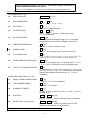
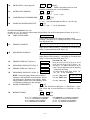
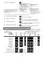
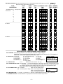
Features Q.E.D. programming for quick
enrollment of devices.
Previous Menu
VISTA-20SE
2-PARTITIONED
SECURITY SYSTEM
PROGRAMMING
FORM
®
Principal changes between the VISTA-20SE and
the former VISTA-20 are indicated by margin lines.
VISTA-20PRV4 8/97 (See Instructions N7526V4)
Local programming requires the use of a 2-line Alpha keypad connected to
partition 1 keypad terminals on the control.
NOTE: For UL installations, the system may be configured as a single partition only.
Field
Function
SYSTEM SETUP (*20–*29)
*20
INSTALLER CODE
*21
Programmed Values
[
] = Default Value
| | |
[4 1 1 2]
Enter 4 digits, 0–9
QUICK ARM ENABLE
[0]
Part.
1†
Part.2 †
0 = no; 1 = yes
*22
RF SYSTEM
[0]
0 = none; 1 = 5800 (5881/5882)
*23
FORCED BYPASS
[0] [0]
Part.
Part. 2† 0 = none; 1 = bypass open zones
“0”. for UL installations.
1†
*24
RF HOUSE ID CODE
*25
WIRED ZONE EXPANSION
|
[0][0]
00 = disable all wireless keypad usage; 01–31 = using 5827
keypad; Partition 2 RF House ID = Partition 1 House ID +1
† [0]
CHIME BY ZONE
0 = none; 1 = 4219; 2 = 4229; 3 = 4204
† [0]
*26
0 = no; 1 = yes (program zones to chime on zone list 3)
*27
X–10 HOUSE CODE
[0]
0 = A; 1 = B, 2 = C, 3 = D, 4 = E, 5 = F, 6 = G, 7 = H, 8 = I, 9 =
J, #10 = K, #11 = L, #12 = M, #13 = N, #14 = O, #15 = P
*28
PHONE MODULE ACCESS CODE
|
[00]
(Partition 1 only) 1st digit: enter 1–9; 2nd digit: enter # + 11 for " *
", or # + 12 for "#". Entering 0 for either digit disables code.
*29
OUTPUT TO LONG RANGE RADIO
[0]
0 = disable; enable = Trouble code 1–9, B (# +11), C (# + 12), D
(# + 13), E (# + 14), or F (# + 15). The 2nd digit of Trouble Dialer
Report is automatically entered from field * 60. “0” for UL
installations.
ZONE SOUNDS AND TIMING (*31–*39)
*31
SINGLE ALARM SOUNDING/ZONE
*32
*33
† [0]
FIRE SOUNDER TIMEOUT
1 = yes; 0 = no; “0” for UL installations.
† [0]
ALARM BELL TIMEOUT
0 = timeout; 1 = no timeout
† [1]
0 = none; 1=4 min; 2=8 min; 3=12 min; 4 = 16 min; “1” (4 min.)
minimum for UL.
*34
*35
EXIT DELAY
ENTRY DELAY 1 (zone type 01)
|
|
Part. 1†
Part. 2†
[70] [70]
00-99 = exit delay time for each partition
|
|
[30] [30]
†
†
Part. 1
Part. 2
00-99 = entry delay 1 time for each
partition; 20 seconds max. for UL installations
† Entry of a number other than one specified will give unpredictable results.
–2–
*36
ENTRY DELAY 2 (zone type 02)
|
[60] [60]
†
†
Part. 1
Part. 2
00-99 = entry delay 2 time for each
partition; 50 seconds max. for UL installations
*37
AUDIBLE EXIT WARNING
[1] [1]
†
Part. 1
Part. 2 † 0 = no; 1 = yes
*38
CONFIRMATION OF ARMING DING
*39
POWER UP IN PREVIOUS STATE
[0] [0]
Part. 1 † Part. 2 †
0 = no; 1 = yes (wired keypads and RF); 2 = yes, RF only
† [1]
|
0 = no; 1 = yes; “1” for UL installations
DIALER PROGRAMMING (*40–*53)
In fields * 40, *41, *42, enter up to the number of digits shown. Do not fill unused spaces. Enter 0–9; #+11 for '*';
#+12 for '#'; #+13 for a pause.
*40
PABX ACCESS CODE
| | | | |
Enter 6 digits. If fewer than 6 digits are entered, exit by
pressing * (and press 41, if entering next field). To clear entries
from field, press *40* .
*41
PRIMARY PHONE No.
|
| | |
| | | | | | | | |
| |
Enter up to 16 digits; Do not fill unused spaces. If fewer than 16
digits entered, exit by pressing * (and press 42, if entering next
field). To clear entries from field, press * 41* .
*42
SECONDARY PHONE No.
|
| | |
| | | | | | | | |
| |
Enter up to 16 digits; Do not fill unused spaces. If fewer than 16
digits entered, exit by pressing * (and press 43, if entering next
field). To clear entries from field, press *42* .
*43
PRIMARY SUBS ACCT # (Part. 1)
|
|
|
*44
SECONDARY SUBS ACCT # (Part. 1)
|
|
|
*45
PRIMARY SUBS ACCT # (Part. 2)
|
|
|
*46
SECONDARY SUBS ACCT # (Part. 2)
|
|
|
*47
*48
For fields *43 - *46:
Enter 0–9; #+11 for B; #+12 for C; #+13
for D; #+14 for E; [#+15 for F]. Enter * as
4th digit, if 3+1 dialer reporting is to be
used. If only 3 digits used, exit by pressing
* (and press next field).
To clear entries from field, press *43*
,*44* , *45* , or * 46* .Examples:
For Acct. 1234, enter:
1 | 2 | 3 | 4
NOTE: If using the paging feature, do not enter a
leading 0 in the subscriber account number, and do
For Acct. B234, enter: #+11| 2 | 3 | 4
not use digits A-F anywhere in the number. Some
For Acct. 123, enter:
1 | 2 | 3 | *
paging systems provide voice mail capability, which
is activated by a leading 0 in the message.
† [1]
PHONE SYSTEM SELECT
If Cent. Sta. IS NOT on a WATS line: 0 = Pulse Dial; 1 = Tone
Dial; if Cent. Sta. IS on a WATS line: 2 = Pulse Dial ; 3 = Tone
Dial.
REPORT FORMAT
[7] [0]
Primary
Secondary
0 = 3+1, 4+1 ADEMCO L/S STANDARD
1 = 3+1, 4+1 RADIONICS STANDARD
2 = 4+2 ADEMCO L/S STANDARD
3 = 4+2 RADIONICS STANDARD
6 or undefined = 4+2 ADEMCO EXPRESS
7 = ADEMCO CONTACT ID REPORTING
8 = 3+1, 4+1 ADEMCO L/S EXPANDED
9 = 3+1, 4+1 RADIONICS EXPANDED
† Entry of a number other than one specified will give unpredictable results.
–3–
*49
SPLIT/DUAL REPORTING
[0]
0 = Disable (Backup report only)
TO PRIMARY PHONE No.
TO SECONDARY PHONE No.
1 = Alarms, Restore, Cancel
Others
2 = All except Open/Close, Test
Open/Close, Test
3 = Alarms, Restore, Cancel
All
4 = All except Open/Close, Test
All
5 = All
All
TO PRIMARY PHONE No.
TO PAGING No. * (Secondary)
** A 10-digit code is sent to the pager consisting
6 = All except Open/Close
** Alarms, Open/Close, Troubles
of a 4-digit subscriber number, a 3-digit event code,
7 = All reports
** Alarms, Troubles
and a 3-digit user or zone number.
8 = All reports
* * Alarms, Open/Close, Troubles
See Installation Instructions for an explanation
9 = All except Open/Close
* * A l a r ms , O p e n / Cl o s e f o r
of the 10-digit code.
us ers 5-25 (us ers 5-16 or
wi r e l e s s b u t t o n z o n e s 1 0 2 5 ) , Tr o u b l e s
* Ca n o n l y b e u s e d i f p r i ma r y r e p o r t i n g f o r ma t i s A d e mc o Co n t a c t I D.
*50
*51
*52
† [0]
15 SEC DIALER DELAY (BURG)
PERIODIC TEST REPORT
0 = no; 1 = yes; “0” for UL installations
† [0]
TEST REPORT OFFSET
0 = none; 1 = 24 hours; 2 = weekly; 3 = 30 days (Enter Test
Code in field * 64. Reports with Partition 1 subscriber No.)
† [2]
0 = 24 hour; 1 = 6 hours; 2 = 12 hours; 3 = 18 hours (Time to 1st
report from programming or downloading).
*53
SESCOA/RADIONICS SELECT
[0]
0 = Radionics (0–9, B–F reporting); 1 = SESCOA (0–9 only
reporting). Select 0 for all other formats.
† Entry of a number other than one specified will give unpredictable results.
*56
ZONE ASSIGNMENT/ALARM REPORT CODES —This field is an interactive mode. Fill in the required
data on the worksheet below (and on next page) and follow the programming procedure in the installation
manual.
See explanation of headings on next page ·
ZONES ON CONTROL:
ZONE
ZONE
ZONE
PART'N ALARM RPT CODE INPUT
RESPONSE
DESCRIPTION
No.
TYPE
No.
(Hex)
TYPE
TIME
(Zn)
(ZT)
(P)
(RC)
(In)
(RT)
Wired Zone 1*
0
1
HW
Wired Zone 2
0
2
HW
Wired Zone 3
0
3
HW
Wired Zone 4
0
4
HW
Wired Zone 5
0
5
HW
Wired Zone 6
0
6
HW
Wired Zone 7
0
7
HW
Wired Zone 8**
0
8
HW
Expansion Module
Supervision
0
9
0
5
Both
Ñ
Ñ
Duress
9
2
—
—
Both
Ñ
Ñ
9
5
Both
Ñ
Ñ
Console Panic (3 & #, or C)
9
6
Both
Ñ
Ñ
Console Panic (* & #, or B)
9
9
Both
Ñ
Ñ
Console Panic (1 &
*, or A)
* Zone 1 can be used as a 2-wire Fire zone.
**Zone 8 can be used as a Glassbreak zone.
–4–
EXPANSION ZONES: Assign zone numbers (Zn) 10–17 to 4219/4229 Auxiliary Wired Loops A–H, if used.
ENTER FOR
RF ONLY
RF zones can use zone numbers (Zn) 10–31
[
[
ZONE
DESCRIPTION
4219/4229 Loop A 1st Exp'n Zone
or RF Zones
ZONE
No.
(Zn)
1
0
B
1
1
C
1
2
D
1
3
E
1
4
F
1
5
G
1
6
H
1
7
1
8
1
9
2
0
2
1
2
2
2
3
2
4
2
5
2
6
2
7
2
8
2
9
3
0
3
1
3
2
3
3
RF Zones
RF Zones
ZONE
TYPE
(ZT)
PART'N ALARM RPT CODE
No.
(Hex)
(P)
(RC)
INPUT LEARNED
TYPEÊÊÊÊRF INPUT
(In)
(L)
EXPLANATION OF ZONE ASSIGNMENT TABLE HEADINGS
Zn = ZONE No. Zone Nos. are from 01 to 31, 92, 95, 96, 99. Some are pre-assigned.
With Field * 25 set for auxiliary wired loops (4219, or 4229), use Zone Nos. 10–17 for loops A–H.
With Field * 22 set for RF (5800), use Zone Nos. 10-31.
ZT = ZONE TYPE 00 = Not Used
01 = Entry/Exit #1
02 = Entry/Exit #2
03 = Perimeter
04 = Interior Follower
05 = Trouble Day/Alarm Night
06 = 24 Hr Silent
07 = 24 Hr Audible
08 = 24 Hr Aux
09 = Fire
10 = Interior w/Delay
20 = Arm–Stay
21 = Arm–Away
22 = Disarm
23 = No Alarm Response
24 = Silent Burglary
ÊÊDEFAULT VALUES
Zn: 01 02 03 04
ZT: [09] [01] [03] (03)
Zn: 05 06 07 08 99
ZT: [03] [03] [03] [03] [06]
P = PARTITION No.
1 or 2
Default Values for zones 01 – 08 = [1].
RC = ALARM REPORT CODE Two Hex Digits.
For each Hex Digit, enter: 00–09 for 0–9, 10 for A, 11 for B,12 for C, 13 for
D, 14 for E, 15 for F. If "00" is entered as the first digit, there will be no report for that zone.
For contact ID reporting, this is enabling code only. Enter any hex digit (other than 00) in
the first pair of boxes. The second pair of boxes is ignored.
In = LOOP INPUT TYPE HW: Hard Wire
Enter 2 for AW: Auxiliary wired
Hard wire zone input
AW: Aux Wire (4219 or 4229) Enter 3 for RF: Supervised RF
types are automatically
Enter 4 for UR: Unsupervised RF
assigned.
Enter 5 for BR: Button Type RF
RT = RESPONSE TIME 0 = 10msec; 1 = 350 msec; 2 = 700 msec. Default Values for zones 01 – 08 = 1 (350 msec)
L = LEARNED RF INPUT Used with 5800 RF Loop Input Devices. Record transmitter input number.
–5–
TO PROGRAM SYSTEM STATUS, & RESTORE
REPORT CODES (*59Ð*76, & *89):
With a 3+1 or 4+1 Standard Format: Enter a code in the first
box: 1–9, 0, B, C, D, E, or F. Enter "#+10" for 0, "#+11" for B,
"#+12" for C, "#+13" for D, "#+14" for E, "#+15" for F.
A "0" ( not "#+10") in the first box will disable a report.
A "0" ( not "#+10") in the second box will result in auto matic
advance to the next field when programming.
With an Expanded or 4+2 Format: Enter codes in both boxes
(1st and 2nd digits) for 1–9, 0, or B–F, as de scribed above.
A "0" ( not "#+10") in the second box will eliminate the expanded message for that report.
A "0" ( not "#+10") in both boxes will disable the report.
With Ademco Contact ID Reporting: Enter any digit (other
than "0") in the first box, to enable zone to report (entries in the
second boxes will be ignored).
A "0" ( not "#+10") in the first box will disable the report.
Examples:
For Code 3 (single digit), enter:
3 | 0
For Code 3 2 (two digits), enter:
For Code B 2 (Hexadecimal), enter:
*75
RF XMTR LO BAT RST RPT CODE
*76
TEST RESTORE RPT CODE
*80
OUTPUT RELAYS AND
POWERLINE CARRIER
DEVICES
ZONE LISTS FOR OUTPUT
DEVICES
*81
*82
Program only if
Relays and/or
Powerline Carrier
devices are to be
used. See next page.
CUSTOM ALPHA EDITING: (Also entered from field
*56):
*83
See procedure in instructions.
SEQUENTIAL LEARN MODE (Also entered from
field *56): See procedure in instructions.
*89
EVENT LOG 80% FULL RPT CODE
*90
|
EVENT LOGGING
3 | 2
[3]
0 = None; 1 = Alarm/Alarm Restore;
2 = Trouble/Trouble Restore; 4 = Bypass/Bypass
Restore; 8 = Open/Close.
Example: To select “Alarm/Alarm Restore”, and
“Open/Close”, enter 9 (1 + 8); To select all, enter #15.
Note: System messages are logged when any nonzero selection is made.
#+11 | 2
*59
EXIT ERROR REPORT CODE
*60
TROUBLE REPORT CODE
|
*61
BYPASS REPORT CODE
|
*91
*62
AC LOSS REPORT CODE
t
|
*63
LOW BAT REPORT CODE
t
|
*64
TEST REPORT CODE
*65
OPEN REPORT CODE
OPTION SELECTION (AAV)
*92
PHONE LINE MONITOR ENABLE
Part. 1
††
Part. 2
††
*93
No. OF REPORTS IN ARMED PERIOD
DOWNLOAD INFORMATION ( *94, *95)
††
*94
|
AWAY STAY
† 2nd digit is automatically sent as the 2nd digit of the
zone alarm report code programmed in * 56, if
expanded or 4+2 report ing is selected.
†† 2nd digit is automatically sent as the user number if
expanded or 4+2 reporting is selected.
*67
RF XMTR LOW BAT REPORT CODE
|
*68
CANCEL REPORT CODE
|
[0]
0 = 10 Alarm/Alarm Restore Reports; 1 = Unlimited.
“1” for UL installations.
††
Part. 2
[0]
0 = Not used
1 = Keypad display when line is faulted
2 = Keypad display plus keypad trouble sound
3 = Same as “2”, plus Device #2 STARTS. If either
partition is armed, external sounder activates also.
Note:Ê Device #2 must either be programmed to be
STOPPED in field *80 or STOPPED by Code + # + 8 + 2.
|
ARM AWAY/STAY RPT CODE Part. 1
[0]
0 = None; 4 = AAV;“0” for UL installations.
AWAY STAY
DOWNLOAD PHONE No.
| | |
| | | | |
|
|
|
|
|
*95
RING DET COUNT FOR DOWNLOADING[0]
0 = Disable Station Initiated Download; 1–14 = number
of rings (1–9, # +10 =10, # +11 =11, # +12 =12,
# +13 =13, # +14 =14); 15 = answering machine defeat
(# +15 =15)
Note: Do not enter “0” if using 4285 Voice Module.
ALARM RESTORE RPT CODE
2nd digit is automatically sent as the 2nd digit of
the zone alarm report code programmed in *56, if
expanded or 4+2 re porting is selected.
*96
INITIALIZES DOWNLOAD ID, SUBSCRIBER
ACCOUNT No. FOR INITIAL DOWNLOAD:
*97
SETS ALL PROGRAM FIELDS TO DEFAULT
VALUES: No data entry required.
No data entry required.
*71
TROUBLE RESTORE RPT CODE
|
*72
BYPASS RESTORE RPT CODE
|
*73
AC RESTORE RPT CODE
t
|
*74
LOW BAT RESTORE RPT CODE
t
|
|
Enter up to 16 digits, 0–9; #+11 for '*'; #+12 for '#'; #+13 for
a pause. Do not fill unused spaces. If fewer than 16 digits
entered, exit field by pressing * (and press 95, if entering
next field). To clear entries from field, press *94 *.
Note: In UL installations, down loading may only be
performed if a technician is at the site.
RESTORE REPORT CODES (*70– *76)
Default for all restore report codes = [00]
*70
|
OUTPUT AND SYSTEM SETUP (*80– *93)
SYSTEM STATUS REPORT CODES (*59– * 68)
Default for all report codes = [00]
*66
|
*98
*99
t Reports with Partition 1 Subscriber No.
–6–
Exits programming mode and prevents re-entry
by: Installer Code + 8+ 0 + 0. If *98 is used to
exit programming mode, system must be
powered down, and method 1 above used to
enter the programming mode.
Exits programming mode and allows re-entry
by: Installer Code + 8 + 0 + 0 or: Power-up, then
press " *" and "#" within 50 seconds of power up.
OUTPUT RELAYS/POWERLINE CARRIER DEVICES WORKSHEET FOR *80, and *81.
Applicable only if Relays and/or Powerline Carrier Devicess are to be used.
80 OUTPUT DEVICES – This is an interactive menu mode. Fill in the required data on the worksheet on below and follow
*
the programming procedure in the installation manual as you enter the data during the displays and prompts that appear
in sequence.
Notes: 1. For Relays, field *25 must be programmed for a 4229 (Relays 01 and 02), OR for a 4204 (Relays 01 to 04).
2. For Powerline Carrier devices, field *27 must be programmed with a House Code.
3. Tampers of expansion units cannot be used to operate devices.
S T A R T
S T O P
=either or both DEVICE
NUMBER
ACTION
(A)
EVENT
(EV)
ZONE
LIST
(ZL)
ZONE TYPEÊÊPART'N
SYST OP'N
No.
ÊÊÊÊÊ(ZT)
(P)
ÊÊÊÊÊÊÊÊÊÊÊÊ= either or both RESTORE of
ZONE LIST
(ZL)
ZONE TYPEÊÊÊÊPART'N
/SYST OP'N
No.
(ZT)
(P)
X-10
SELECT
OUTPUT RELAY
OR P.L.C.D.* 01
OUTPUT RELAY
OR P.L.C.D.* Ê02
OUTPUT RELAY
OR P.L.C.D.* Ê Ê03
OUTPUT RELAY
OR P.L.C.D.* ÊÊ04
P.L.C.D.* ÊÊÊÊÊÊÊÊ05
P.L.C.D.* ÊÊÊÊÊÊÊÊ06
P.L.C.D.* ÊÊÊÊÊÊÊÊ07
P.L.C.D.* ÊÊÊÊÊ ÊÊ08
+ * P.L.C.D. = Powerline Carrier Device (X-10).
Where:
X-10 SELECT = Powerline Carrier Device Enter “1” if Powerline Carrier Device is being used, enter “0” if relay is being used.
A = DEVICE ACTION 0 = No Response; 1 = Close for 2 sec; 2 = Close and stay closed; 3 = Pulse on and off.
EVÊ = EVENT
0 = Not used; 1 = Alarm; 2 = Fault; 3 = Trouble.
Z L = ZONE LIST 1, 2, or 3 (from Field *81) or 0 = Not Used.
"START" ZONE LIST: Upon alarm, fault, or trouble of ANY zone on this list, device action will START.
"STOP" RESTORE of ZONE LIST: Upon restore of ALL zones on this list, device action will STOP. It
need not be same list as used for START.
NOTE: Do not use input type "BR" transmitters in a zone list to STOP a relay action, since these
transmitters do not send restores.
ZT = ZONE TYPE/SYSTEM OPERATION
Choices for Zone Types are:
00 = Not Used
06 = 24 Hr Silent
Note : Any zone in "ZT" going into alarm,
01 = Entry/Exit#1
07 = 24 Hr Audible
fault, or trouble will actuate relay.
02 = Entry/Exit#2
08 = 24 Hr Aux
Any zone of that type that restores
03 = Perimeter
09 = Fire Trouble
will stop relay action.
04 = Interior Follower
10 = Interior w/Delay
05 = Trouble Day/Alarm Night
24= Silent Burglary
Choices for System Operation are:
20 = Arming–Stay
38 = Chime
21 = Arming–Away
39 = Any Fire Alarm
22 = Disarming (Code + OFF)
40 = Bypassing
31 = End of Exit Time
41 = **AC Power Failure
32 = Start of Entry Time
42 = **System Battery Low
33 = Any Burglary Alarm
43 = Communication Failure
36 = **At Bell Timeout***
** Use 0 (Any) for Partition No. (P) entry.
*** Or at Disarming, whichever occurs earlier.
P = PARTITION No.ÊÊ1, 2, or 0 for Any
–7–
52 = Kissoff
58 = Duress
Note: In normal operation mode:
Code + # + 7 + N Key Entry starts Device N.
Code + # + 8 + N Key Entry stops Device N.
81
*
ZONE LISTS FOR OUTPUT DEVICES – This is an interactive mode. Fill in the required data on the worksheet
below and follow the procedure in the installation manual as you enter the data during the displays and prompts that
appear in sequence.
Note:
Record desired zone numbers below. More or fewer boxes than shown may be needed, since any list may
include any or all of system's zone numbers.
Zone List 1: Started or stopped by zone numbers (enter 00 to end entries).
,
,
,
,
,
,
,
,
,
...etc.
,
,
...etc.
Zone List 2: Started or stopped by zone numbers (enter 00 to end entries).
,
,
,
,
,
,
,
Zone List 3: Started or stopped by zone numbers AND/OR assignment of Chime zones (enter 00 to end entries)
,
,
,
,
,
,
,
,
,
...etc.
,
,
,
...etc.
Zone List 4: Assignment of common lobby zones (enter 00 to end entries).
,
,
,
,
,
,
SPECIAL MESSAGES
OC = OPEN CIRCUIT (no communication between Console and Control).
EE or ENTRY ERROR = ERROR (invalid field number entered; re-enter valid field number).
After powering up, AC, dI (disabled) or Busy Standby and NOT READY will be displayed after approximately 4 seconds. This
will revert to READY in appx. 1 minute, which allows PIRS, etc. to stabilize. To bypass this delay, press: [#] + [0].
If E4 or E8 appears, more zones than the expansion units can handle have been programmed. Correct the programming and
then completely de-power and re-power the control to clear this indication and remove the disable indication.
TO ENTER PROGRAMMING MODE:
1. POWER UP, then depress [*] and [#] both at once, within 50 seconds of powering up.
OR
2. Initially, key: Installer Code (4 + 1 + 1 + 2) plus 8 + 0 + 0.
OR
3. If different Installer Code is programmed, key: New Installer Code + 8 + 0 + 0.
(if * 98 was used to exit previously, method 1 above must be used to enter the program mode again)
TO EXIT PROGRAMMING MODE:
*98
Exits programming mode and prevents re-entry by: Installer Code + 8+ 0 + 0. If *98 is used to exit programming
mode, system must be powered down, and method 1 above used to enter the programming mode.
*99
Exits programming mode and allows re-entry by: Installer Code + 8 + 0 + 0 or: Power-up, then press "* " and "#"
within 50 seconds of power up.
®
A L A RM DE V I CE MA NUFA CTURI NG CO .
A DIVISION OF PITTWAY CORPORATION
165 Eileen Way, Syosset, New York 11791
Copyright © 1997 PITTWAY CORPORATION