1
Model 591XV
Owner's Guide
Limited Lifetime
Consumer Warranty
Directed Electronics promises to the original purchaser to repair or replace with a
comparable reconditioned model any Directed Electronics unit (hereafter the "unit"),
excluding without limitation the siren, the remote transmitters, the associated
sensors and accessories, which proves to be defective in workmanship or material
under reasonable use during the lifetime of the vehicle provided the following conditions are met: the unit was professionally installed and serviced by an authorized
Directed Electronics dealer; the unit will be professionally reinstalled in the vehicle
in which it was originally installed by an authorized Directed Electronics dealer; and
the unit is returned to Directed Electronics, shipping prepaid with a legible copy of
the bill of sale or other dated proof of purchase bearing the following information:
consumer's name, telephone number and address; the authorized dealers name, telephone number and address; complete product description, including accessories; the
year, make and model of the vehicle; vehicle license number and vehicle identification number. All components other than the unit, including without limitation the
siren, the remote transmitters and the associated sensors and accessories, carry a
one-year warranty from the date of purchase of the same. This warranty is non-transferable and is automatically void if: the original purchaser has not completed the
warranty card and mailed it within ten (10) days of the date of purchase to the
address listed on the card; the unit's date code or serial number is defaced, missing
or altered; the unit has been modified or used in a manner contrary to its intended
purpose; the unit has been damaged by accident, unreasonable use, neglect,
improper service, installation or other causes not arising out of defects in materials
or construction. The warranty does not cover damage to the unit caused by installation or removal of the unit. Directed Electronics, in its sole discretion, will determine
what constitutes excessive damage and may refuse the return of any unit with excessive damage. TO THE MAXIMUM EXTENT ALLOWED BY LAW, ALL WARRANTIES,
INCLUDING BUT NOT LIMITED TO EXPRESS WARRANTY, IMPLIED WARRANTY, WAR RANTY OF MERCHANTABILITY, FITNESS FOR PARTICULAR PURPOSE AND WARRANTY OF
NO N - I N F R I N G E M E N T O F I N T E L L E C T U A L P R O P E R T Y , A R E E X P R E S S L Y E X C L U D E D ; A N D
DIRECTED ELECTRONICS NEITHER ASSUMES NOR AUTHORIZES ANY PERSON OR ENTITY
TO ASSUME FOR IT ANY DUTY, OBLIGATION OR LIABILITY IN CONNECTION WITH ITS
PRODUCTS. DIRECTED ELECTRONICS DISCLAIMS AND HAS ABSOLUTELY NO LIABILITY
FOR ANY AND ALL ACTS OF THIRD PARTIES INCLUDING ITS AUTHORIZED DEALERS OR
INSTALLERS. DIRECTED ELECTRONICS SECURITY SYSTEMS, INCLUDING THIS UNIT, ARE
DETERRENTS AGAINST POSSIBLE THEFT. DIRECTED ELECTRONICS IS NOT OFFERING A
GUARANTEE OR INSURANCE AGAINST VANDALISM, DAMAGE OR THEFT OF THE AUTOMOBILE, ITS PARTS OR CONTENTS; AND HEREBY EXPRESSLY DISCLAIMS ANY LIABILITY
© 2005 Directed Electronics—all rights reserved
i
WHATSOEVER, INCLUDING WITHOUT LIMITATION, LIABILITY FOR THEFT, DAMAGE
AND/OR VANDALISM. THIS WARRANTY DOES NOT COVER LABOR COSTS FOR MAINTE NANCE, REMOVAL OR REINSTALLATION OF THE UNIT OR ANY CONSEQUENTIAL
DAMAGES OF ANY KIND. IN THE EVENT OF A CLAIM OR A DISPUTE INVOLVING
DIRECTED ELECTRONICS OR ITS SUBSIDIARY, THE PROPER VENUE SHALL BE SAN DIEGO
COUNTY IN THE STATE OF CALIFORNIA. CALIFORNIA STATE LAWS AND APPLICABLE
FEDERAL LAWS SHALL APPLY AND GOVERN THE DISPUTE. THE MAXIMUM RECOVERY
UNDER ANY CLAIM AGAINST DIRECTED ELECTRONICS SHALL BE STRICTLY LIMITED TO
THE AUTHORIZED DIRECTED ELECTRONICS DEALER'S PURCHASE PRICE OF THE UNIT.
DIRECTED ELECTRONICS SHALL NOT BE RESPONSIBLE FOR ANY DAMAGES WHATSOEVER,
INCLUDING BUT NOT LIMITED TO, ANY CONSEQUENTIAL DAMAGES, INCIDENTAL
DAMAGES, DAMAGES FOR THE LOSS OF TIME, LOSS OF EARNINGS, COMMERCIAL LOSS,
LOSS OF ECONOMIC OPPORTUNITY AND THE LIKE. NOTWITHSTANDING THE ABOVE, THE
MANUFACTURER DOES OFFER A LIMITED WARRANTY TO REPLACE OR REPAIR THE
CONTROL MODULE AS DESCRIBED ABOVE. Some states do not allow limitations on how
long an implied warranty will last or the exclusion or limitation of incidental or consequential damages. This warranty gives you specific legal rights and you may also
have other rights that vary from State to State.
This product may be covered by a Guaranteed Protection Plan ("GPP"). See your
authorized Directed Electronics dealer for details of the plan or call Directed
Electronics Customer Service at 1-800-876-0800. Directed Electronics security systems,
including this unit, are deterrents against possible theft. Directed Electronics is not
offering a guarantee or insurance against vandalism, damage or theft of the automobile, its parts or contents; and hereby expressly disclaims any liability whatsoever,
including without limitation, liability for theft, damage and/or vandalism. Directed
Electronics does not and has not authorized any person or entity to create for it any
other obligation, promise, duty or obligation in connection with this security system.
Make sure you have all of the following information from your dealer:
A clear copy of the sales receipt, showing the following:
■
■
■
■
■
■
■
■
■
ii
Date of purchase
Your full name and address
Authorized dealer's company name and address
Type of alarm installed
Year, make, model and color of the automobile
Automobile license number
Vehicle identification number
All security options installed on automobile
Installation receipts
© 2005 Directed Electronics—all rights reserved
Table of Contents
Limited Lifetime Consumer Warranty . . . . . . . . . . . . . . . . . . . . . . . . . . . . . . . i
What is Included . . . . . . . . . . . . . . . . . . . . . . . . . . . . . . . . . . . . . . . . . . . . 3
Important Information . . . . . . . . . . . . . . . . . . . . . . . . . . . . . . . . . . . . . . . . 3
Your Warranty . . . . . . . . . . . . . . . . . . . . . . . . . . . . . . . . . . . . . . . . . . . . . . . 4
FCC/ID Notice . . . . . . . . . . . . . . . . . . . . . . . . . . . . . . . . . . . . . . . . . . . . . . . 4
Caution. . . . . . . . . . . . . . . . . . . . . . . . . . . . . . . . . . . . . . . . . . . . . . . . . . . . 4
Remote Control Diagram . . . . . . . . . . . . . . . . . . . . . . . . . . . . . . . . . . . . . . . 5
Standard Remote Configuration . . . . . . . . . . . . . . . . . . . . . . . . . . . . . . . . . . . 6
System Maintenance . . . . . . . . . . . . . . . . . . . . . . . . . . . . . . . . . . . . . . . . . . . 7
Remote Control Functions . . . . . . . . . . . . . . . . . . . . . . . . . . . . . . . . . . . . . . . 7
Standard Button Configurations . . . . . . . . . . . . . . . . . . . . . . . . . . . . . . . . . . . 8
Standard Icon Configurations . . . . . . . . . . . . . . . . . . . . . . . . . . . . . . . . . . . . . 9
Remote Operation and Programming . . . . . . . . . . . . . . . . . . . . . . . . . . . . . . . . 11
System Signal Paging Features . . . . . . . . . . . . . . . . . . . . . . . . . . . . . . . . . . . . 12
Command Page. . . . . . . . . . . . . . . . . . . . . . . . . . . . . . . . . . . . . . . . . . . . . . . 12
Page Recognition Mode . . . . . . . . . . . . . . . . . . . . . . . . . . . . . . . . . . . . . . . . . 12
Programmable Remote Control Features . . . . . . . . . . . . . . . . . . . . . . . . . . . . . . 13
Using Your System . . . . . . . . . . . . . . . . . . . . . . . . . . . . . . . . . . . . . . . . . . . 14
Warning! Safety First . . . . . . . . . . . . . . . . . . . . . . . . . . . . . . . . . . . . . . . . . . 14
Locking. . . . . . . . . . . . . . . . . . . . . . . . . . . . . . . . . . . . . . . . . . . . . . . . . . . . 17
Unlocking . . . . . . . . . . . . . . . . . . . . . . . . . . . . . . . . . . . . . . . . . . . . . . . . . . 18
Disabling the Starter Kill Without a Transmitter . . . . . . . . . . . . . . . . . . . . . . . . 19
Valet Mode . . . . . . . . . . . . . . . . . . . . . . . . . . . . . . . . . . . . . . . . . . . . . . . . . 19
Panic Mode . . . . . . . . . . . . . . . . . . . . . . . . . . . . . . . . . . . . . . . . . . . . . . . . . 20
Remote Start . . . . . . . . . . . . . . . . . . . . . . . . . . . . . . . . . . . . . . . . . . . . . . . . 21
Rear Defogger . . . . . . . . . . . . . . . . . . . . . . . . . . . . . . . . . . . . . . . . . . . . . . . 22
Valet Take-Over . . . . . . . . . . . . . . . . . . . . . . . . . . . . . . . . . . . . . . . . . . . . . . 23
Short-Run/Turbo. . . . . . . . . . . . . . . . . . . . . . . . . . . . . . . . . . . . . . . . . . . . . . 24
Timer Mode . . . . . . . . . . . . . . . . . . . . . . . . . . . . . . . . . . . . . . . . . . . . . . . . . 24
Starter Anti-Grind Circuitry . . . . . . . . . . . . . . . . . . . . . . . . . . . . . . . . . . . . . . 25
Disabling the Remote Start System . . . . . . . . . . . . . . . . . . . . . . . . . . . . . . . . . 26
© 2005 Directed Electronics—all rights reserved
1
Rapid Resume Logic . . . . . . . . . . . . . . . . . . . . . . . . . . . . . . . . . . . . . . . . . .
Programming Options . . . . . . . . . . . . . . . . . . . . . . . . . . . . . . . . . . . . . . . . .
Glossary of Terms . . . . . . . . . . . . . . . . . . . . . . . . . . . . . . . . . . . . . . . . . . . .
Convenience Expansions . . . . . . . . . . . . . . . . . . . . . . . . . . . . . . . . . . . . . . .
Notes . . . . . . . . . . . . . . . . . . . . . . . . . . . . . . . . . . . . . . . . . . . . . . . . . . . .
Quick Reference Guide: . . . . . . . . . . . . . . . . . . . . . . . . . . . . . . . . . . . . . . . .
2
26
27
28
29
31
33
© 2005 Directed Electronics—all rights reserved
What is Included
■
The control module
■
An XHF2 receiver/antenna
■
One four-button LCD transmitter
■
A blue status LED indicator light
■
A push-button Valet switch
■
Your warranty registration
■
A shut-down toggle switch
Important Information
Congratulations on the purchase of your remote start keyless entry
system. Due to the complexity of this system, it must be installed
by an authorized dealer only. Installation of this product by anyone other than an authorized dealer voids the warranty. All dealers are provided with a preprinted dealer certificate to verify that
they are authorized.
By carefully reading this Owner's Guide prior to using your system,
you will maximize the use of this system and its features.
You can print additional or replacement copies of this manual by
accessing
the
Directed
Electronics
internet
website
at
www.directed.com.
© 2005 Directed Electronics—all rights reserved
3
Your Warranty
Your warranty registration must be completely filled out and
returned within 10 days of purchase. Your product warranty
will not be validated if your warranty registration is not returned.
Make sure you receive the warranty registration from your dealer.
It is also necessary to keep your proof of purchase, which reflects
that the product was installed by an authorized dealer.
FCC/ID Notice
This device complies with Part 15 of FCC rules. Operation is subject
to the following conditions: (1) This device may not cause harmful
interference, and (2) This device must accept any interference received, including interference that may cause undesirable operation.
Changes or modifications not expressly approved by the party responsible
for compliance could void the user's authority to operate this device.
Caution
This product is designed for fuel injected, automatic transmission
vehicles only. Use of this product in a standard transmission vehicle is dangerous and contrary to the product's intended use.
4
© 2005 Directed Electronics—all rights reserved
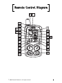
Remote Control Diagram
© 2005 Directed Electronics—all rights reserved
5
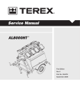
Standard Remote Configuration
1. Auxiliary Channel Out
2. Receive Indicator
3. Signal Indicator
4. Transmit Indicator
5. Lock Status Indicator
6. Unlock Status Indicator
7. Not applicable
8. Not applicable
9. Not applicable
10. Not applicable
11. Siren Status Indicator
12. Battery Level Indicator
13. Trigger Response Indicator
14. Not applicable
15. Ignition Switch Input Indicator
16. Not applicable
17. Not applicable
18. Not applicable
19. Not applicable
20. Vibrate Mode Indicator
21. Remote Start Indicator
22. Unlock Button
23. Remote Start Button
24. Auxiliary Button
25. Lock Button
6
© 2005 Directed Electronics—all rights reserved
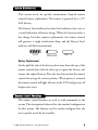
System Maintenance
This system needs no specific maintenance beyond remote
control battery replacement. The remote is powered by a 1.5V
AAA battery.
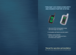
The Battery Level indicator has four level indicators that serve as
a visual indication of battery charge. When the battery reaches a
low charge level that requires replacement, the remote control
will generate a single notification chirp, and the Battery Level
indicator will flash continuously.
FULL
REPLACE
EMPTY
Battery Replacement
Gently pull the end of the battery door away from the top of the
remote control then slide the door up to expose the battery and
remove the expired battery. Place the new battery into the remote
control observing the correct polarity. When power is returned
the remote control will light all icons in the LCD and generate all
beeper tones once.
Remote Control Functions
The remote control buttons are used to send commands to the
system. The descriptions below reflect the standard configuration
for this system. The buttons can be custom configured for the
user’s specific needs by the installer.
© 2005 Directed Electronics—all rights reserved
7
Standard Button Configurations
Button
Controls the system Lock function by pressing this button for
one second.
Button
Controls the system Unlock function by pressing this button for
one second.
Button
Controls an optional Auxiliary function, such as trunk release by
pressing this button for 1.5 seconds.
The auxiliary output controls __________________________.
Button
Controls Remote Start feature by pressing this button two times.
and
Buttons
Controls and optional auxiliary channel output for a convenience
or expansion feature that has been added to your system. This
feature is operated by pressing these buttons simultaneously.
The auxiliary output controls __________________________.
and
and
Buttons
When simultaneously pressed these buttons control the rear
window defogger during remote starting.
8
© 2005 Directed Electronics—all rights reserved
Standard Icon Configurations
Icon
The transmit icon will be displayed while the remote control is
transmitting a command to the vehicle.
Icon
The receive icon will be displayed while the remote control is
receiving a page from the vehicle.
Icon
The signal icon will be displayed if a command is transmitted to
the vehicle but a command page is not received.
Icon
The locked status icon will be displayed when the system is locked.
Icon
The unlock status icon will be displayed when the system is
unlocked.
Icon
The disarm icon will flash when the system is unlocking the
doors.
Icon
The arm icon will flash when the system is locking the doors.
Icon
Not applicable.
© 2005 Directed Electronics—all rights reserved
9
Icon
Not applicable.
Icon
The siren icon will display when a security feature has been triggered.
Icon
The siren icon will display when a security feature has been triggered. This icon will remain displayed until the system’s page is
cleared.
Icon
The vibrate icon will be displayed when the Vibrate Mode is on.
Icon
The battery level icon is always displayed as an indicator of
Battery charge.
Icon
The start icon will be displayed while the vehicle is remote started.
note: If Page Mode has been turned off, the start icon will
remain when performing key take over until a button on
the transmitter has been pressed.
Icon
Not applicable.
Icon
Not applicable.
10
© 2005 Directed Electronics—all rights reserved
Icon
Not applicable.
Icon
Not applicable.
note: The icons which are ‘not applicable’ are only used
when incorporated with a ESP2 Directed Security/Remote
Start system.
Icon
The ignition icon will display if the ignition is turned on when
the system (doors) are locked.
Icon
Not applicable.
Number Icons
When either of the channel 2 or 4 outputs is activated the appropriate icon will be displayed for five seconds.
Remote Operation and Programming
The remote start system operates at 434 MHz and incorporates
Directed’s proprietary XHF2 out-board Responder Technology
remote control. The high frequency combined with Binary Data
communication achieves superior range with two-way communication.
© 2005 Directed Electronics—all rights reserved
11
System Signal Paging Features
A page is the signal the 542 control module sends to the remote
control as confirmation of receipt of a command.
When the remote control receives a page it will generate a page
notification to the user (notifications are audible beeps or remote
vibration) and the LCD Icons will display the current system
status.
Command Page
When a command (lock/unlock, remote start, or auxiliary
channel) from the remote control is sent and received, the system
will send a command page back to confirm receipt.
note: When the system is in Valet mode, the remote control will show the lock (5) and unlock (6) icons, but will
not generate a command page.
Page Recognition Mode
The remote control will leave a zone icon illuminated when it
has received a triggered response and will wait for you to recognize the violation. Press any button on the remote control, the
LCD information and Alarm Page alerts will be cleared.
note: The remote control buttons will not send a command to the system until the alarm page is cleared.
12
© 2005 Directed Electronics—all rights reserved
Programmable Remote Control Features
To enter programming mode
Press and hold all four remote control buttons simultaneously
until one long beep is heard. Programming Mode has now been
entered.
Page Notification
The remote control can be programmed to notify the user of a
page by audibly beeping or remote vibration.
Beep Mode
Beep Mode includes alarm arm/disarm diagnostic beeps and distinctive two-tone remote start beeps.
Vibrate Mode
Vibrate Mode makes page notification silent but does not include
diagnostic information or distinctive remote start notification.
Illumination
Illumination for the LCD display can be programmed on or off.
When programmed on the LCD will illuminate every time the
remote control receives a page or transmits a command.
Programming illumination on will decrease the life expectancy of
the battery.
Beep/Vibrate Mode
Within five seconds of entering Programming Mode, press
.
The remote control will beep once for on, twice for off. The
vibrate icon (13) will also turn on/off with each press.
© 2005 Directed Electronics—all rights reserved
13
Illumination On/Off
Within five seconds of entering Programming Mode, press
.
The remote will beep once for on, twice for off and the light will
turn on/off with each press.
Page Mode On/Off
After entering Programming Mode, press
within five
seconds to toggle on and off. When the Page Mode is on, the
remote control will wake up periodically to check for messages
from the security module. It will also wake up when any button
is pushed. When Page Mode is off, the remote control “sleeps”
until a button is pushed, extending the life of the battery.
To Exit Programming Mode
To exit Programming Mode, take no action for five seconds. The
remote control will generate two beeps to indicate programming
mode has been exited.
Using Your System
Warning! Safety First
The following safety warnings must be observed at all times:
■
Due to the complexity of this system, installation of this
product must only be performed by an authorized Directed
Electronics dealer.
14
© 2005 Directed Electronics—all rights reserved
■
When properly installed, this system can start the vehicle via
a command signal from the remote control transmitter.
Therefore, never operate the system in an enclosed area or
partially enclosed area without ventilation (such as a
garage). When parking in an enclosed or partially enclosed
area or when having the vehicle serviced, the remote start
system must be disabled using the installed toggle switch. It
is the user's sole responsibility to properly handle and keep
out of reach from children all remote control transmitters to
assure that the system does not unintentionally remote start
the vehicle. THE USER MUST INSTALL A CARBON MONOXIDE
DETECTOR IN OR ABOUT THE LIVING AREA ADJACENT TO THE
VEHICLE. ALL DOORS LEADING FROM ADJACENT LIVING AREAS
TO THE ENCLOSED OR PARTIALLY ENCLOSED VEHICLE STORAGE
AREA MUST AT ALL TIMES REMAIN CLOSED. These precautions
are the sole responsibility of the user.
© 2005 Directed Electronics—all rights reserved
15
■
Use of this product in a manner contrary to its intended mode
of operation may result in property damage, personal injury,
or death. (1) Never remotely start the vehicle with the vehicle in gear, and (2) Never remotely start the vehicle with the
keys in the ignition. The user must also have the neutral
safety feature of the vehicle periodically checked, wherein
the vehicle must not remotely start while the car is in gear.
This testing should be performed by an authorized Directed
Electronics dealer in accordance with the Safety Check outlined in the product installation guide. If the vehicle starts
in gear, cease remote start operation immediately and consult with the authorized Directed Electronics dealer to fix the
problem.
■
After the remote start module has been installed, contact
your authorized dealer to have him or her test the remote
start module by performing the Safety Check outlined in the
product installation guide. If the vehicle starts when performing the Neutral Safety Shutdown Circuit test, the remote
start unit has not been properly installed. The remote start
module must be removed or the installer must properly reinstall the remote start system so that the vehicle does not
start in gear. All installations must be performed by an
authorized Directed Electronics dealer. OPERATION OF THE
REMOTE START MODULE IF THE VEHICLE STARTS IN GEAR IS
CONTRARY TO ITS INTENDED MODE OF OPERATION. OPERAT ING THE REMOTE START SYSTEM UNDER THESE CONDITIONS
MAY RESULT IN PROPERTY DAMAGE OR PERSONAL INJURY.
16
© 2005 Directed Electronics—all rights reserved
YOU MUST IMMEDIATELY CEASE THE USE OF THE UNIT AND
SEEK THE ASSISTANCE OF AN AUTHORIZED DIRECTED ELEC TRONICS DEALER TO REPAIR OR DISCONNECT THE INSTALLED
REMOTE START MODULE. DIRECTED ELECTRONICS WILL NOT BE
HELD RESPONSIBLE OR PAY FOR INSTALLATION OR REINSTAL LATION COSTS.
Locking
Pressing
for one second arms the system by activating the
starter kill and locking the doors (if the door locks are connected). The horn will honk (if connected) and the parking lights will
flash once to confirm arming of the system. While the system is
armed, the status LED will flash once per second. The Failsafe®
Starter Kill will also prevent the vehicle’s starter from cranking.
The system can also be programmed to arm the optional Failsafe®
Starter Kill automatically (called Passive Mode). If the system has
been programmed for Passive Mode, the Failsafe® Starter Kill will
automatically activate 30 seconds after the ignition has been
turned off. After the ignition has been turned off, the status LED
will flash rapidly to indicate that the system is in Passive Mode.
© 2005 Directed Electronics—all rights reserved
17
If Passive Mode has been programmed on, then it is also possible
to program the system for Passive Locking. With Passive Locking,
the vehicle doors lock automatically at the same time that the
Failsafe® Starter Kill is activated. If Passive Locking is programmed
on, care must be taken to prevent the keys from being locked in the
vehicle.
NOTE: For Passive Mode to be effective, the Failsafe® Starter Kill relay
must be installed.
Unlocking
Pressing
for one second disarms the system and unlocks the
doors (if connected). The horn will honk twice (if connected) and
the parking lights will flash twice to confirm disarming of the system. The optional Failsafe® Starter Kill will be deactivated. The status LED will turn off, unless the system is programmed for Passive
Mode. In Passive Mode, the status LED will flash rapidly when the
system is disarmed. This indicates that the system will re-engage
the starter kill and re-lock the doors (if Passive Locking has been
programmed) in 30 seconds unless the ignition is turned on.
18
© 2005 Directed Electronics—all rights reserved
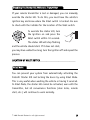
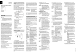
Disabling the Starter Kill Without a Transmitter
If your remote transmitter is lost or damaged, you can manually
override the starter kill. To do this, you must have the vehicle's
ignition key and know where the Valet switch is located. Be sure
to check with the installer for the location of the Valet switch.
To override the starter kill, turn
the ignition on and press the
Valet switch within 10 seconds.
The status LED will stop flashing
DRW-35
and the vehicle should start. If it does not start,
you may have waited too long; turn the ignition off and repeat the
process.
LOCATION OF VALET SWITCH_____________________________
Valet Mode
You can prevent your system from automatically activating the
Failsafe® Starter Kill and locking the doors by using Valet Mode.
This is very useful when washing the vehicle or having it serviced.
In Valet Mode, the starter kill cannot be activated, even with the
transmitter, but all convenience functions (door locks, remote
start, etc.) will continue to work normally.
© 2005 Directed Electronics—all rights reserved
19
To enter or exit Valet Mode:
1. Turn the ignition on.
2. Turn the ignition off.
3. Press and release the Valet
switch within 10 seconds.
DRW-35
The status LED will light steadily if you are entering Valet Mode
and will turn off if you are exiting Valet Mode.
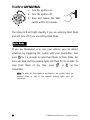
Panic Mode
If you are threatened in or near your vehicle, you can attract
attention by triggering the system with your transmitter. Just
press
for 1.5 seconds to enter Panic Mode. In Panic Mode, the
horn will honk and the parking lights will flash for 30 seconds. To
stop Panic Mode at any time, press
, or
on the
transmitter.
NOTE: In order for Panic Mode to be effective, the vehicle’s horn (or
optional siren) as well as the vehicle's parking lights must be
connected.
20
© 2005 Directed Electronics—all rights reserved
Remote Start
This feature allows you to remotely start and run your vehicle for
a programmable period of time. This makes it possible to warm up
the engine, as well as adjust the interior temperature of the vehicle with the climate control system. If interior heating or cooling
is desired, the climate controls must be preset, and the fan blower
must be set to the desired level prior to remote starting the
vehicle.
IMPORTANT! (1) Never remotely start the vehicle with the vehicle
in gear, and (2) Never remotely start the vehicle with the key in the
ignition.
To remote start the vehicle:
1.
Press
on the transmitter 2 times.
2.
The parking lights will flash to confirm that the vehicle will
attempt to start.
3.
Release the
buttons as soon as the parking lights flash.
(In gasoline vehicles, the engine will start 4 seconds after
the parking lights flash. In diesel vehicles, the engine will
start when the WAIT-TO-START indicator on the vehicle's dash
goes out.)
4.
Once the vehicle has started, it will run for the pre-programmed period of time (either 12, 24, or 60 minutes - see
Programming Options section of this guide) or until a shutdown input is triggered.
© 2005 Directed Electronics—all rights reserved
21
When you are ready to drive the vehicle:
1. Insert the ignition key and
turn it to the ON (not the
START) position.
2. Press the brake pedal.
NOTE: If the brake pedal is pressed before the key is in the ON position,
the engine will shut down.
While the vehicle is running during remote start operation, the
system will monitor the vehicle and will automatically shut down the
engine if the system receives any of the following shut-down inputs:
■
The brake pedal is pressed.
■
The hood is opened.
■
The shutdown toggle switch is put into the OFF position.
■
The pre-programmed run time (12, 24, or 60 minutes) has elapsed.
■
Transmitter button
is pressed again twice to start the
vehicle.
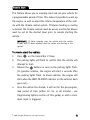
Rear Defogger
To turn the rear defogger output OFF:
1. Simultaneously press & release the
+
+
but-
tons on the remote control.
2. The lights will flash 2 times.
3. The rear defogger output will no longer activate when the
vehicle is remote started.
NOTE: If the remote start is on the parking lights will turn off then flash
2-times before returning to their normal output and the defogger output, if active, will cease.
22
© 2005 Directed Electronics—all rights reserved
To turn the rear defogger output ON:
1. Simultaneously press & release the
+
+
but-
tons on the remote control.
2. The lights will flash 3 times.
3. The rear defogger output will once again activate when
the vehicle is remote started.
NOTE: If the remote start is on the lights will turn off then flash 3-times
before returning to their normal output and the defogger output will
activate as programmed.
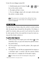
Valet Take-Over
The Valet Take-Over feature allows the vehicle to remain running
after the key has been removed from the ignition. This feature is
useful for occasions when you wish to exit and lock the vehicle
for short periods of time, but would like to leave the motor running and the climate controls on.
To perform Valet Take-Over:
1.
Before turning off the engine, press and release
on the
transmitter twice (or press and release the optional momentary switch twice).
2.
Turn the ignition key to the OFF position. (The engine will
stay running.)
3.
The engine will run until the pre-programmed time elapses or
a shut-down input is received. (See the previous Remote
Start section for a complete list of shut-down inputs.)
NOTE: This feature will not work if the brake pedal is being pressed.
© 2005 Directed Electronics—all rights reserved
23
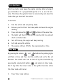
Short-Run/Turbo
Short run turbo mode keeps the engine running after arriving at
you destination for a programmable period of 1, 3, 5 or 10 minutes. This allows the system’s timer to conveniently cool down the
turbo after you have left the vehicle.
To activate:
1.
Park the vehicle and set parking brake.
2.
Remove your foot from the brake pedal and leave the engine
running.
3.
Press and release the
and
buttons at the same time.
4.
The lights will flash to indicate the remote start has entered
short run turbo mode.
5.
Turn off the key, the engine will keep running.
6.
Exit and secure the vehicle.
7.
The engine will turn off after the programmed run time.
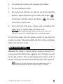
Timer Mode
By pressing the remote
and
buttons the parking lights
will flash 4 times and then start the vehicle and run for the set
duration. The remote start can be shut off by the transmitter by
pressing the remote start button
and remain in timer mode,
but if any other shut down zones or the ignition becomes active
the timer mode will cancel.
1.
24
Press Timer mode buttons.
© 2005 Directed Electronics—all rights reserved
2.
The vehicle will confirm with 4 parking light flashes.
3.
A 1-second delay will start.
4.
The system will start the car and will run for the specified
duration, unless shut down by the remote start button
If shut down with the remote start button
.
the system
will remain in timer mode.
5.
The system will start every 3 hours until canceled by the
brake, hood, or neutral safety shut-down wires.
IMPORTANT! Timer Mode should be used only in open areas. Never start
and run the vehicle in an enclosed space such as a garage or carport.
To exit timer mode, turn the ignition switch on any time the
engine is running. The parking lights will flash 4 times, indicating
timer mode has been exited.
Starter Anti-Grind Circuitry
Whenever the vehicle is remote started, advanced anti-grind circuitry prevents the starter from engaging, even if the key is turned
to the start position. This prevents damage to the starter motor if
the key is turned to the start position during remote start operation.
NOTE: Anti-grind circuitry only works when the remote start system is
operating the motor and the Failsafe® Starter Kill relay is installed.
© 2005 Directed Electronics—all rights reserved
25
Disabling the Remote Start System
This feature allows your system's remote start unit to be temporarily disabled to prevent the vehicle from being remote started
accidentally. This feature is useful if the vehicle is being serviced
or stored in an enclosed area. To disable the remote start, move
the shutdown toggle switch to the OFF position. The switch can
be installed in a location of your choice. Check with your installer
for recommended locations.
LOCATION OF SHUTDOWN SWITCH_________________________
Rapid Resume Logic
This Directed Electronics system will store its current state to nonvolatile memory. If power is lost and then reconnected the system
will recall the stored state from memory. This means if the unit is
in Valet Mode and the battery is disconnected for any reason, such
as servicing the car, when the battery is reconnected the unit will
still be in Valet Mode. This applies to all states of the system
including arm, disarm, VRS®, and Valet Mode.
26
© 2005 Directed Electronics—all rights reserved
Programming Options
Programming options control your system's normal, operational
set-up. Most options do not require additional parts, but some may
require additional installation labor. This system's programming
options are listed below, with the factory default settings in bold:
■
12, 24, or 60 minute run time. your system can be programmed to allow the vehicle to run for 12, 24, or 60 minutes when remote started. Can be set up to minute increments by your installer.
■
3, 6, 9, or 12 minute timer mode run time. Your system can
be programmed to allow the vehicle to run for 3, 6, 9, or 12
minutes when remote started in timer mode. Can be set up to
16 minutes by your installer.
■
Comfort closure is a programming option which closes the
vehicle’s windows after remote locking.
■
Parking lights flashing or constant. Your system can be programmed to either flash or to turn on the parking lights constantly during the entire remote start operation.
■
Passive Mode or Active Mode. In Passive Mode the Failsafe®
Starter Kill will automatically activate 30 seconds after the
ignition has been turned off.
■
Ignition switch-controlled door-locking on or off. With this
feature on, the doors will lock 3 seconds after the ignition
key is turned on, and unlock when the ignition key is turned off.
© 2005 Directed Electronics—all rights reserved
27
■
Passive Locking or Active Locking (doors lock only with the
transmitter). With Passive Locking, the vehicle doors lock
automatically 30 seconds after the ignition has been turned
off. Passive Locking can only be selected when the system
has been programmed for Passive Mode.
■
The horn honk confirmations for locking and unlocking can
be programmed on or off. In order for this feature to be programmed on, the horn must be connected to the system.
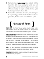
Glossary of Terms
Control Unit: The “brain” of your system. Usually hidden underneath the dash area of the vehicle. It houses the microprocessor
which monitors your vehicle and controls all system functions.
Failsafe® Starter Kill: An automatic switch controlled by your system which prevents the vehicle’s starter from cranking whenever
the system is armed. The vehicle is never prevented from cranking
when the system is disarmed, in Valet Mode, or if the starter kill
switch itself fails. Your system has feature-ready circuitry for the
starter kill, however installation may require additional labor.
LED: A red light mounted at a discretionary location inside the
vehicle. It is used to indicate the status of your system.
Transmitter: A hand-held, remote control which operates the various functions of your system.
28
© 2005 Directed Electronics—all rights reserved
Valet Switch: A small push button mounted at a discretionary location inside the vehicle. It is used to override the Failsafe® Starter
Kill when a transmitter is lost or damaged, or to enter or exit Valet
Mode.
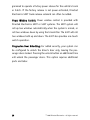
Convenience Expansions
Listed below are some of the many expansion options available for
use with your system. Some options may require additional parts
and/or labor. Please consult with your dealer for a complete list of
options available for use with this system.
Domelight Supervision: The domelight will illuminate for 30 seconds each time the system is disarmed using the transmitter.
This is useful for seeing inside the vehicle at night prior to
entering it.
Power Door Lock Control: Your system is capable of controlling
many types of power door lock systems; however, some door lock
systems may require extra parts. Consult with your dealer to determine which type of locks your vehicle uses. If power locks are
connected, the system can be programmed to lock the doors automatically 30 seconds after the ignition has been turned off. The
system can also be programmed to lock the doors when the ignition
is turned on and to unlock them when the ignition is turned off.
Power Trunk Release: The system’s auxiliary output can be pro© 2005 Directed Electronics—all rights reserved
29
grammed to operate a factory power release for the vehicle's trunk
or hatch. If the factory release is not power-activated, Directed
Electronics 522T trunk-release solenoid can often be added.
Power Window Control: Power window control is provided with
Directed Electronics 529T or 530T systems. The 529T system will
roll up two windows automatically when the system is armed, or
roll two windows down by using the transmitter. The 530T will roll
two windows both up and down. The 530T also provides one touch
switch operation.
Progressive Door Unlocking: For added security, your system can
be configured to unlock the driver’s door only, leaving the passenger doors locked. Pressing the unlock button an additional time
will unlock the passenger doors. This option requires additional
parts and labor.
30
© 2005 Directed Electronics—all rights reserved
Notes
© 2005 Directed Electronics—all rights reserved
31
32
© 2005 Directed Electronics—all rights reserved
✂
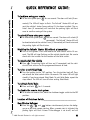
QUICK REFERENCE GUIDE :
To lock/arm using your remote
Cut along dotted line and fold for a quick and easy reference to keep in your purse or wallet.
■ To arm the system press
for one second. The doors will lock (if con-
nected). The LED will begin to flash. The Failsafe® Starter Kill will prevent the vehicle’s starter from cranking if it has been installed. The vehicle’s horn (if connected) will honk and the parking lights will flash
once to confirm arming of the system.
To unlock/disarm using your remote
■ To disarm the system press
for one second. The doors will unlock (if
connected). The Failsafe® Starter Kill will
be deactivated and the vehicle’s horn (if connected) will honk twice and
the parking lights will flash twice.
Disabling the Failsafe® Starter Kill without a transmitter
■ Turn on the ignition. Press and release the Valet switch within 10 seconds. The LED will stop flashing and the vehicle should start. Be sure to
check with the installer for the location of the Valet switch.
To remote start the vehicle
■ Press
. The parking lights will turn on (if connected) and the vehicle will start and run for the programmed amount of time.
To enter or exit Valet Mode
■ Turn the ignition to the "ON" position. Turn the ignition back off. Press
and release the Valet switch within 10 seconds. The status LED will light
steadily if you have entered Valet Mode. To exit Valet Mode, repeat the
steps above. The LED will turn off when exiting Valet Mode.
To activate Panic Mode
■ Press and hold
for 1.5 seconds.
To disable the remote start system
■ To disable the remote start, move the shutdown toggle switch to the OFF
position.
Location of Shutdown Switch______________________________
✂
Rear Window Defogger
■ Press the
,
and
buttons simultaneously to turn the defogger on or off when remote starting. When a remote start is initiated, the
parking lights will flash 2-times if the defogger is set to off, and will
© 2005 Directed Electronics—all rights reserved
33
The company behind this system is Directed Electronics
Since its inception, Directed Electronics has had one purpose, to provide consumers
with the finest vehicle security and car stereo products and accessories available. The
recipient of nearly 100 patents and Innovations Awards in the field of advanced electronic
technology, Directed Electronics is ISO 9001 registered.
Quality Directed Electronics products are sold and serviced throughout North America
and around the world.
Call (800) 274-0200 for more information about our products and services.
Directed Electronics is committed to delivering world class quality products
and services that excite and delight our customers.
Directed Electronics
Vista, CA 92081
www.directed.com
© 2005 Directed Electronics—All rights reserved
G542V 07-05