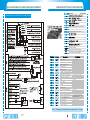
1
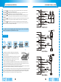
Thank you for purchasing Long-Range Two-Way FM Vehicle Security System
This vehicle security system features a state-of-the-art technology and FM design
to give you maximum safety and satisfaction in using the system.
180 days
1) Please read this manual carefully before using this car alarm so that you'll take
the full advantage of every marvelous features provided by the system.
2) The local authorized dealer is responsible for the service and warranty.
3) The system requires no specific maintenance. Your remote control is powered
by a small 1.5volt LR03 AAA Alkaline battery. When the battery weakens,
operating range will be shortened. When the battery icon "
" begins flashing on
the LCD screen, please replace the battery.
4) This device complies with part 15 of FCC rules. Operation is subject to the
following two conditions: (1). This device may not cause harmful interference,
and (2) This device must accept any interference received, including interference
that may cause undesired operation. Changes or modifications not expressly
approved by the party responsible for compliance could void the user's authority
to operate this device.
5) Due to the complexity of this system, it must be installed by an authorized dealer only.
6) All the modules and interconnection cables are inaccessible to the end user except
the remote control, the communication unit and its signal cables.
Valet Switch
22
TABLE OF BUTTONS CONFIGURATION
QUICK REFERENCE GUIDE FOR SYSTEM WIRING
Quick Reference Guide for System Wiring
L
U
R
A
D
O
Ignition On or Triggered by Illegal Start
Hood Opened
Triggered by Microwave Sensor
L
F
Keypad is Locked
Silent Arming
C
RTC Mode
ARM
TURBO
LIGHT
Mode
Battery Life Indicator
Auxiliary Output
The System is in Arming Mode
The Engine is in Short-Run/Turbo Mode
The LCD Back Light is Enable
Arm and Lock
2.0sec
Panic Mode
2.0sec
Trunk Release
Non-driving
Disarm and Unlock
Remote Query
2.0sec
Auxiliary Channel 5 Output
Remote Start Timer Mode
Non-driving, Armed
Remote Start ON/OFF
Lock
2.0sec
Driving
Anti-robbery
Unlock
Turbo Mode
2.0sec
To Activate Set-up Menu
Any time
Keylock ON/OFF
Hours or Minutes Increment
2.0sec
Hours or Minutes Increase
Continuously
Function Select
Correction of Real-time
Clock or Time Set-up for
Personal Alarm
Menu Activated
Function Cancel
Function Shift
Note:
21
+ means press the buttons in sequence within 2 seconds.
FEATURES PROGRAMMING ROUNTINE
FEATURES DESCRIPTION
Standard Arming Mode
Checklist of Options
Parking
Windows Rolling-up
If you hear three more chirps after arming, maybe you need to re-check the doors to see whether they
are properly closed. This chirp is called door zone bypass notification. This notification is given out
when some door is not closed properly or if your car has a dome light delay. After the notification, the
system will delay to monitor the door zone for an additional 20 seconds or until the dome light turns off.
The system also can remind you of arming the system if you forgot to do so. The system will give out
three siren chirps with light flashes 20 seconds after you turn off the ignition key and close all the doors.
After hearing the audible reminder, you should press button
to arm and lock.
If you select to install a Field Disturbance Sensor, such as a microwave sensor, the system can react to
any intrusions into the field with the full triggered sequence.
Note: This system supplies a windows rolling-up feature. A windows rolling-up module may be necessary.
When Alarm is Triggered (In Arming State)
Light
Heavy
Door/hood/trunk was
illegally opened
10.Parking Lights
Flashing/Constant
Parking
twice
Parking
Parking
Flashing
Parking
Short
Rolling
20
Constant
FEATURES PROGRAMMING ROUNTINE
FEATURES DESCRIPTION
Program Features
STEP1
STEP2
STEP3
d: You may select an optional field disturbance sensor such as microwave sensor or radar sensor,
your system can react to any intrusions into this field with the full triggered sequence.
Four
OFF
Silent Arming Mode
STEP4
Parking
four
switch the same number of times
as the desired feature number of
which is going to be programmed
goes off
Flashes the
same number of times
STEP5
Silent Arming Mode
select the first option
One
Parking
once
STEP5
Silent Arming Mode
select the second option
Two
Parking
two
STEP5
Multi-Level Security Arming
select the third option
5
Three
Parking
three
Note: Repeat step4 and step5 for each feature to be changed. If no
programming activity occurs within a 10 second period, the Features
Programming Mode will expire.
19
The system will enter the
Multi-Level Security Mode
Flashes the
same number of times as
button
pressed
Multi-Level Security Arming allow you to select which of the system's inputs or sensors will be active and
which will be bypassed when the system is armed. Each time Button
is pressed again, a different security
level is selected. The different security levels are selected as follows:
SYSTEM INSTALLATION
FEATURES DESCRIPTION
1.Press Button
once: The siren chirps once. The system is armed. All zones are active. LED indicator
blinks once and then pauses for 2.0 seconds and then repeats.
2.Press Button
a second time within 5 seconds: The siren chirps once again. The shock sensor zone is
now bypassed. LED indicator blinks twice with a two-second pause and then repeats.
3.Press Button
a third time within 5 seconds: The siren chirps one more time. The Optional sensor zone
(Microwave sensor zone) is now bypassed. LED indicator blinks three times with a two-second pause and
then repeats.
4.Press Button
a fourth time within 5 seconds: The siren chirps one more time. The Shock sensor zone and
Microwave sensor zone are now bypassed. LED indicator blinks four times with a two-second pause and
then repeats.
5.Press Button
a fifth time within 5 seconds: The siren chirps one more time. The Shock sensor zone,
Microwave sensor zone. Hood Pin Switch input and trunk pin switch input are now bypassed. LED indicator
blinks five times with a two-second pause and then repeats.
Note: Multi-Level Security Arming only applies to a single arming cycle. Once the system is disarmed
and then re-armed, all the zones (inputs) will be active again.
Disarming
Parking
Dome light is turned on
1.Tamper Alert: If you hear four additional siren chirps and light
flashes, please check your car to see whether the security system was
triggered in your absence.
2.Security Rearming (Programmable): The system will re-enter into last
arming mode automatically if no door is opened or ignition is still off
within 35s after disarmed by remote. This feature is to protect your car
from theft even when your car is disarmed by accident.
3. Central Lock Automation (Programmable): This function enables your vehicle to automatically lock the
doors upon pressing brake pedal after ignition is on and unlock the doors upon key off. During driving, you may
also press button A to lock or button B to unlock without activating security mode.
4. Automatic Dome Light: The system will turn on the dome light every time you disarm your system. The dome
light will go out 30 seconds later or immediately go out after you turn the ignition on.
5. Passive Arming and Passive Locking: The system also can be programmed to arm itself automatically (call passive arming). Once passive arming is enable, the system will arm itself in 40 seconds every time after the system
sees you turn ignition off and leave your car by opening and closing the doors. If passive locking function is
enable, the system will lock doors at the same time when entering passive arming.
SYSTEM INSTALLATION
FEATURES DESCRIPTION
Query Function
Panic Mode
16
2
To stop Panic Mode at any time, press button
The system will enter
Panic Mode
Parking
16
for 2.0sec again or press button
for 0.5sec.
2
You may select whether disarm and unlock doors when trunk released by options.(This function is suitable
for cars with electric trunk opener)
Auxiliary Output (Programmable)
AUX
2
Auxiliary channel 5 output
Turn on
Auxiliary channel 5 output is programmed to output pulse of 0.5 seconds, 15 seconds or latched signal,
reset with ignition.
FEATURES DESCRIPTION
SYSTEM INSTALLATION
Remote Engine Start (Must Need Remote Start Module)
Pin 4: GREY WIRE: Hood Pin Input (-). Connect this wire to the hood pin switch. The switch must supply a
ground output(-)when switch is opened. This input will disable or shut down the remote start when the hood is
opened. It will also trigger the security system if the hood is opened while the system is armed.
Pin 5: BROWN WIRE: Brake Input (+). Connect to the wire that shows +12V when pressing the brake. The
brown wire is a safety shutdown wire that must be connected.
In arming state
Pin 6: YELLOW WIRE: (+) Ignition Input of the Key Cylinder to Alarm. Connect to the ignition wire that
provides +12V when the ignition is on and while cranking the starter.
Parking
Pin 7: GREEN WIRE: Negative Door Input (-). Most vehicles use negative door trigger circuit. Connect the
green wire to the wire that shows ground when any door is opened. In vehicles with factory delays on the domelight circuit, there is usually a wire that is unaffected by the delay circuit.
Rolling
Parking
Air-conditioner begins
to work for 15 or 25
minutes duration
Peripheral Plug-in Connectors
Note: 1. The parking lights will flash every 30 seconds during the engine is running
2.Never start the vehicle if it is not in either PARK or NEUTRAL position and never forget to
activate the parking brake before remote start.
3.In gasoline vehicles, the engine will wait 6 seconds to start after the parking lights flash. In diesel
vehicles, the engine will start when the WAIT-TO-START indicator on the vehicle's dash goes out.
4.It is unsafe to remote start the vehicle in a garage or other enclosed area. Breathing the exhaust
from the vehicle is hazardous to your health.
How to Drive Your Remote Started Vehicle:
1) Press button
0.5s to unlock and disarm and open the door.
2) Insert the ignition key and turn it to the ON (not the START) position in 30 seconds.
3) Press the brake pedal.
Note: If the brake pedal is pressed before the key is in the ON position, the engine will shut down.
Remote shut down:
While the vehicle is running during remote start operation, the system will monitor the vehicle and will
automatically shut down the engine if the system receives any of the following shut-down inputs:
1)The brake pedal is pressed.
2)The hood is opened.
3)The pre-programmed run time (15 or 25 minutes) has elapsed.
4)Press button
and button
again.
5)The TACH or Oil sensor or High voltage signal disappear.
Disarm the System Without Remote Control
switch
Pin 8: PURPLE WIRE: Positive Door Input (+). Connect to the door switch circuit wire that shows +12V
when any door is opened. This type of door circuit is usually found on Ford Vehicle.
Horn sound twice
Parking lights flash twice
System returns to disarming state
All alarm are released
7-PIN White Connector: Two-way Transceiver Communication Port
3-PIN Black Connector: Optional Sensor Input port, for example, the Microwave Sensor.
2-PIN White Connector: LED Port. Mount LED in an area where it may be easily seen from either side
of the vehicle.
Door Lock Wiring Diagram
SYSTEM INSTALLATION
Pin4: Blue/Black: Unlock #30 Common (Output)
FEATURES DESCRIPTION
Turbo/Short Run
Pin5: Brown/Black: Unlock #87 Normally Open (Input)
Pin6: Violet/Black: Lock #87a Normally Closed
Pin7: Green/Black: Lock #30 Common (Output)
Pin8: White/Black: Lock #87 Normally Open (Input)
Pin9: Red: Constant +12V Input. Connect this wire to the battery or Constant Power wire at the Ignition
Switch with a 15Amp Supply.
Park the vehicle and set parking brake.
Remove your foot from the brake pedal
and leave the engine running.
Pin10: Black: System Ground. Connect this wire firmly to the Chassis Ground.
OFF
6-pin Secondary Harness for Outputs(H2)
Three chirps from the Horn
Pin 1: ORANGE WIRE: Armed Output (-) 500mA. The orange wire supplies a ground output while armed
to activate a relay for starter defeat and anti-grind protection.
Parking lights flash three times
Turn off the ignition key,
the engine will keep running.
Turn on
Pin 2: BLUE WIRE: Second unlock (passenger unlock)output (-) 200mA This system is equipped with a
dedicated passenger unlock output allowing two stage door lock operation. When connected this wire,
disarming the system will unlock only the driver s door. Pressing the disarm button again will unlock all doors..
Pin 3: WHITE/BLACK WIRE: Auxiliary Channel 5 Output (-) 200mA. This wire provides a (-) 200mA
output whenever the transmitter button
is pressed for 2S. This output can be programmed to provide the follo
wing types of outputs:
a.0.8-second timed: Output that will send a ground pulse of 0.8 second.
b.15-second timed: Output that will send a ground continuous pulse for 15 seconds.
c.Latched,reset with ignition: Output that will send a signal when the Channel 5 button (button ) is pressed and
will continue until the same button (button
) is pressed again. It additionally stops output whenever the ignition
is turned on.
Pin 4: PURPLE/BLACK WIRE: Auxiliary 4 Output (-)500mA for windows rolling-up option. Connect to
a power window module.
Exit and secure the vehicle.
Press button
for 0.5s to
arm and lock the car.
The engine will turn off after
the programmed run time.
Note: Once you activate the short-run turbo mode, the system will remain this mode always. If you don t
want this mode any more, press button + again to cancel it anytime.
Remote Start Timer Mode
Pin 5: BLACK/WHITE WIRE: Dome Light Output (-) 500mA. Connect to the wire that activate the vehicle's
dome light, usually the door pin switch wire. Note: the dome light output can usually connect to the same wire
used for the door trigger input (see purple and green door input wire).
Note: This output is only intended to drive a relay. It can not be connected directly to the dome light
circuit, as the output cannot support the current draw of one or more light bulbs.
Never use this wire to drive anything but a relay or a low-current input. The transistorized output
can only supply 200mA of current. Connecting directly to a solenoid, motor, or other high-current
device will cause it to fail.
Press button
In arming state
for 0.5s.
Four
Flashing slowly
Pin 6: RED/WHITE WIRE: Vehicle Trunk Release Wire (-)500mA. Connect this wire to the electronic
trunk opener. (Relay may required).
8-pin 2510 Harness for Inputs and Outputs(H3)
Pin 1: GREEN/BLACK WIRE: Factory Disarm Output (-) 500mA. This wire provides a ground output on
disarming and before remote starting to disarm a factory security system. Connect to the wire that requires a
ground pulse to disarm the factory security system.
Pin 2: GREEN/WHITE WIRE: Factory Rearm Output (-) 500mA. This wire supplies a ground output on
remote start shutdown to rearm a factory security system. Connect to the wire that requires a ground pulse to
rearm the factory security system.
Pin 3: BLACK WIRE: Optional Sensor Input (-).Connect to an optional instant sensor such as trunk pin switch.
Parking
four times
The system will enter
Remote Start Timer Mode
1.In this mode, the system will start the engine every 3 hours, for a maximum of six cycles. The engine will
run for the programmed run time and then shut down to keep engine warm in the cold weather.
2.The remote start command + can shut down the engine in timer mode, but the system will remain in the
timer mode.
3.To exit timer mode, press button 0.5s to disarm the system, turn the ignition key on and then press the
brake pedal or press button
0.5s and then button
0.5s again.
4.If any other shut down zones or alarm has been triggered, the timer mode will cancel.
SYSTEM INSTALLATION
FEATURES DESCRIPTION
Valet Mode
Harness Description
5 Heavy Gauge Starter Harness in the Starter Module (Ignition Switch Interface)
Purple Wire: Starter Output (+). Connect to the vehicle's starter wire.
hold
switch
3 seconds
ORANGE WIRE: Accessory Output (+). Connect to the accessory wire coming from the ignition switch
that supplies power to the heater/air-conditioner. Some cars may have multiple accessory wires.
PINK WIRE A: Ignition Output (+). Connect to the main ignition wire that provides +12V when the ignition
is on and while cranking the starter.
PINK WIRE B: Second Ignition Output (+). Connect to the second ignition wire of the vehicle.
Three
S
Parking
three times
Status LED goes on solid
RED WIRE: Main Power Input (+). Connect to the battery or constant power wire at the ignition switch with
a minimum 30 Amp supply. Remove the fuse until the installation is completed and all wiring is checked.
7-pin Connector Secondary Harness for Remote Start(H4)
The system will
enter Valet Mode
In Valet Mode ,the alarm works just as a keyless entry (door lock/unlock,
trunk release, car finding) without any security functions. The Status
Indicator will be solid on all the time. To exit the Valet Mode, repeat
above again.
Pin1-3: Factory wiring to the remote start module.
Pin4: BLUE/WHITE WIRE: (-)200ma bypass output when remote start. Connect this wire to the interface
of Remote Start Bypass Module.
Pin 5: GREY/ BLACK WIRE: Diesel wait-to-start bulb input. (-) Connect this wire to the wire in the vehicle that
sends the signal to turn on the WAIT-TO-START bulb in the dashboard. In most diesels, the wire is negative (ground
turns on the bulb) and the GRAY/BLACK wire can be directly connected to the wire in the vehicle. If the vehicle
uses a positive wire (12V to turn on the bulb), you must set the proper signal polarity in the options list(Features #12).
Pin 6: BLACK/WHITE WIRE: (-)Neutral Safety Switch Input. Connect this wire to the PARK/NEUTRAL switch
in the vehicle. This wire will test with ground with the gear selector either in PARK or NEUTRAL. This will prevent
the vehicle from accidentally being started while in a drive gear. This input MUST rest at ground in order for the
remote start system to operate. Connected properly the vehicle will only start while in PARK or NEUTRAL. You may
also connect this wire to the Parking Brake Switch.
Pin 7: VIOLET/WHITE WIRE: Oil Sensor signal(Default), High-Voltage Sensing or Tachometer Input (Optional)Input wir
module with information about the engine's resolution per minute (RPMs). Connect to the vehicle's tach wire.
Common locations for a tachometer wire are the ignition coil, instrument cluster, fuel injectors, or engine computers.
The correct wire shows between 1V to 6V (AC) and fluctuates with the idle of the engine when testing with a
multi-meter capable of testing AC voltage.
Note: This wire has the same function with the High-Voltage sensing input, so it is a alternative solution when
voltage sensing input does not supply satisfactory operation. If connect to the High-Voltage sensing input,
you must coil this wire five loops onto the High-Voltage from the engine distributor.
10-Pin Connector Primary Harness (H1)
Pin 1: BROWN WIRE: Siren Output (+). The brown wire must connect to the red wire of the siren. The black
wire must be grounded.
With one beep
Pin 2: WHITE WIRE: Parking Light Output (+/-) Relay. Connect this wire to the circuit that shows +12V or
ground only when the parking lights are on and set the internal parking light relay jumper to the proper polarity.
For parking light circuits exceeding 10 Amps, a relay is required. For vehicles with independent left and right
parking light circuits, diodes must be installed to keep the circuits separate.
Note: Do not connect the white wire to the vehicles headlight circuit.
Pin3: Violet: Unlock #87a Normally Closed
SYSTEM INSTALLATION
FEATURES DESCRIPTION
System Installation
1.Due to the complexity of this system, installation must only be performed by an authorized dealer.
2.Thoroughly read and become familiar with the installation instructions before beginning the installation.
3.Review system contents:
a.Main Control Unit
b.Siren
c.Communication unit with built-in Shock Sensor and Valet Switch
d.Starter Kill Relay
e.Remote Starter Module with 5-pin Starter Harness.
f.Harness:
4.Verify vehicle is equipped with electronic fuel injection, and starts/idles normally before installation.
5.Determine if vehicle is equipped with a factory theft deterrent system and obtain proper bypass module
if required.
6.Find a location to mount the hood pin switch that will not interfere with the opening of the hood, and
is not in a position that can accumulate water. The hood pin is a safety device that must be installed to
avoid remote starting during engine servicing.
7.Verify with the owner, the mounting locations for all visible components, including the LED and Receiver.
8.Verify with the owner, the optional features of vehicle security system and the features that must be
programmed during installation.
9.Inspect and perform a function test of all vehicle systems before and after the installation.
10.Always use a Volt/ohm meter for testing vehicle circuits. Never use a test light.
11.Always look before drilling any holes or mounting self-tapping screws. Be sure fuel lines and exterior
wiring looms are clear as they are often close to the chassis and difficult to see.
12.Protect all wires running from the engine compartment to the interior of the vehicle by covering with
electrical tape and split loom tubing. Be sure to use a grommet when routing wires through the firewall.
13.Properly fuse any additional accessories such as starter module, window module, door lock actuators,
etc., Making sure to power them separate from the alarm Main Unit. This will ensure the functionality of
the security system in the event of an accessory failure.
14.Remove all fuses to avoid running down the battery during installation.
15.Roll down the driver's side window to avoid locking the ignition keys in the vehicle.
To confirm and save the alarm time settings
with one beep confirmation and Remote Control
enters Personal Alarm mode, icon
appears
on the LCD screen, the time value is the alarm
call time value. Remote Control will shift to RTC
display a little while later.
With two beeps confirmation
Note:Alarm beeping will be activated when time reaches the setting alarm
time and Remote Control will remain in the Personal Alarm mode automatically.
If you want to exit Personal Alarm mode, just press button
for
2sec and then press
for 0.5sec till the icon
flashes, and press button
to cancel PAC Mode.
FEATURES DESCRIPTION
FEATURES DESCRIPTION
The shock sensor is built in the communication unit. You can adjust the shocking sensitivity by changing
the position "H" , "M" , or " L" of the adjustment switch on the communication unit.
Door Status Warning (Programmable)
switch
The lights will flash to inform you that some door is not closed well. When temperately parking, such flashing
may warn coming cars to take care. It is suggested to cancel this feature when your car has a dome light delay.
Status Memory
Press button
for 0.5sec Press button
for 0.5sec
once of the new remote
once of the new remote
This system may remember the status before power off so as to restore the former working status such as arm
mode disarm mode and Valet mode, even if the power supply is destroyed.
Smart LED Indicator
Parking
In arming status: LED flashes the same number as the times of pressing button within 5 seconds.
In turbo state: LED stays solid for 2 seconds, then pause for 2 seconds.
In valet mode: LED stays solid.
ACC, Door, Hood/Trunk triggered: LED stays solid for 0.5 seconds, then pause for 0.5 seconds.
High Frequency
Your system remote control and communication unit are produced by FM technology at 433Mhz.
This provides a cleaner spectrum with less interference and a more stable signal. Enjoy a phenomenal
increase in range, even in areas with high radio interference.
Code Hopping
This system uses code hopping technology to increase the security of the alarm. In case the remote
falls out of sync with the main control unit, it will fail to operate the system. To re-sync the system,
please remove the battery of the remote, wait for 10 seconds and re-power the remote again, and then
press button , the alarm will automatically re-sync and respond to the remotes normally.
Turn on