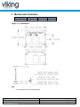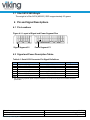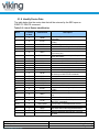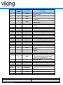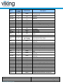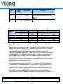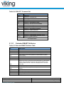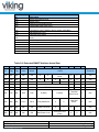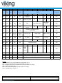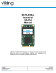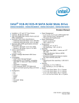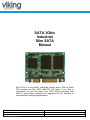
1
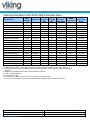
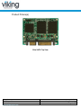
SATA 3Gb/s
Industrial
Slim SATA
Manual
Slim SATA is a non-volatile, solid-state storage device. With its Serial
ATA interface and Slim SATA (MO-297) form factor, it is a drop in
replacement for hard disk drives. Slim SATA delivers extremely high
levels of performance, reliability and ruggedness for I/O intensive or
environmentally challenging applications.
Manual
PSFEM1xxxGQxxx
Revision B
www.vikingtechnology.com
9/11/2014
Viking Technology
Page 1 of 33
Revision History
Date
5/10/13
6/27/13
7/11/13
Revision
A
A1
A2
7/24/13
A3
9/09/13
A4
1/02/14
9/11/14
A5
B
Manual
PSFEM1xxxGQxxx
Revision B
www.vikingtechnology.com
Description
Initial Release
Update PN table for new PN’s
Labeled and revised SMART table
Add SMART table for 3Gps. Revised
performance numbers per lab data.
Added AES info
Add product image to 1st page.
Create separate datasheets for
3Gbps. Revised extended SMART
attributes. Changed Client to
Industrial. Add MLC PN’s. Revised
performance #s. Revised PN table to
avoid confusion on I- temperature
and commercial temperature PN’s.
Checked by
Revised datasheet format
Revise IOP values (7/29/14, A6)
9/11/2014
Viking Technology
Page 2 of 33
Legal Information
Legal Information
Copyright© 2014 Sanmina Corporation. All rights reserved. The information in
this document is proprietary and confidential to Sanmina Corporation. No part of
this document may be reproduced in any form or by any means or used to make
any derivative work (such as translation, transformation, or adaptation) without
written permission from Sanmina. Sanmina reserves the right to revise this
documentation and to make changes in content from time to time without
obligation on the part of Sanmina to provide notification of such revision or
change.
Sanmina provides this documentation without warranty, term or condition of any
kind, either expressed or implied, including, but not limited to, expressed and
implied warranties of merchantability, fitness for a particular purpose, and noninfringement. While the information contained herein is believed to be accurate,
such information is preliminary, and should not be relied upon for accuracy or
completeness, and no representations or warranties of accuracy or
completeness are made. In no event will Sanmina be liable for damages arising
directly or indirectly from any use of or reliance upon the information contained in
this document. Sanmina may make improvements or changes in the product(s)
and/or the program(s) described in this documentation at any time.
Sanmina, Viking Technology, Viking Modular Solutions, and Element logo are
trademarks of Sanmina Corporation. Other company, product or service names
mentioned herein may be trademarks or service marks of their respective
owners.
Manual
PSFEM1xxxGQxxx
Revision B
www.vikingtechnology.com
9/11/2014
Viking Technology
Page 3 of 33
Ordering Information: Slim SATA SSD Solid-State Drive
Part Numbers
VRFEM1008GQCQMxx
VRFEM1016GQCQMxx
VRFEM1032GQCRMxx
VRFEM1064GQCSMxx
VRFEM1008GQIQMxx
VRFEM1016GQIQMxx
VRFEM1032GQIRMxx
VRFEM1064GQISMxx
VRFEM14096QCGSxx
VRFEM18192QCHSxx
VRFEM18192QCQQSxx
VRFEM1016GQCQSxx
VRFEM1032GQCRSxx
VRFEM1064GQCSSxx
VRFEM14096QIGSxx
VRFEM18192QIHSxx
VRFEM18192QIQQSxx
VRFEM1016GQIQSxx
VRFEM1032GQIRSxx
VRFEM1064GQISSxx
SATA
Interface
Application
3Gbps
3Gbps
3Gbps
3Gbps
3Gbps
3Gbps
3Gbps
3Gbps
3Gbps
3Gbps
3Gbps
3Gbps
3Gbps
3Gbps
3Gbps
3Gbps
3Gbps
3Gbps
3Gbps
3Gbps
Industrial
Industrial
Industrial
Industrial
Industrial
Industrial
Industrial
Industrial
Industrial
Industrial
Industrial
Industrial
Industrial
Industrial
Industrial
Industrial
Industrial
Industrial
Industrial
Industrial
Raw
Capacity
(GB)
8
16
32
64
8
16
32
64
4
8
8
16
32
64
4
8
8
16
32
64
Useable
Capacity
(GB)1
8
16
32
64
8
16
32
64
4
8
8
16
32
64
4
8
8
16
32
64
Addressable
Sectors in
LBA Mode
15,625,000
31,277,232
62,533,296
125,045,424
15,625,000
31,277,232
62,533,296
125,045,424
7,812,500
15,625,000
15,625,000
31,277,232
62,533,296
125,045,424
7,812,500
15,625,000
15,625,000
31,277,232
62,533,296
125,045,424
NAND
Technology
MLC
MLC
MLC
MLC
MLC
MLC
MLC
MLC
SLC
SLC
SLC
SLC
SLC
SLC
SLC
SLC
SLC
SLC
SLC
SLC
Temperature
Range
0 to 70c
0 to 70c
0 to 70c
0 to 70c
-40 to 85c
-40 to 85c
-40 to 85c
-40 to 85c
0 to 70c,
0 to 70c
0 to 70c
0 to 70c
0 to 70c
0 to 70c
-40 to 85c
-40 to 85c
-40 to 85c
-40 to 85c
-40 to 85c
-40 to 85c
Notes:
1) Usable capacity based on a level of over-provisioning applied to wear leveling, bad sectors, index tables etc.
2) Higher capacity points may be available based on customer application. Consult your local Viking Field Application
Engineer.
3) SSD’s ship unformatted from the factory unless otherwise requested.
4) 1 GB = 1,000,000,000 Byte
5) One Sector = 512 Byte.
6) Contact Viking for the characters that “x” and “y” represent in the part number.
7) xx is a wild card to indicate customer specific BOM, NAND configuration and/or manufacturing location
Manual
PSFEM1xxxGQxxx
Revision B
www.vikingtechnology.com
9/11/2014
Viking Technology
Page 4 of 33
Product Picture(s)
Slim SATA Top View
Manual
PSFEM1xxxGQxxx
Revision B
www.vikingtechnology.com
9/11/2014
Viking Technology
Page 5 of 33
Industrial SSD – Viking’s Industrial SSD contains sophisticated provisions to
protect firmware and data from corruption due to unexpected power loss.
However, a Industrial SSD by industry definition does not contain on-board
capacitance. Should power fail unexpectedly, “in-flight” write data may be lost.
Industrial SSD’s are best used in designs that manage power fail events at the
system level.
Manual
PSFEM1xxxGQxxx
Revision B
www.vikingtechnology.com
9/11/2014
Viking Technology
Page 6 of 33
Table of Contents
1
INTRODUCTION
10
1.1
Features
10
1.2
Block Diagram
11
1.3
SATA Interface
12
2
2.1
PRODUCT SPECIFICATIONS
Performance
13
13
2.2
Timing
2.2.1 STANDBY IMMEDIATE Command
13
14
2.3
Electrical Characteristics
2.3.1 Absolute Maximum Ratings
2.3.2 Supply Voltage
2.3.3 Power Consumption
14
14
14
15
2.4
Environmental Conditions
2.4.1 Temperature and Altitude
2.4.2 Shock and Vibration
2.4.3 Electromagnetic Immunity
15
15
15
15
2.5
Reliability
16
2.6
Data Security
16
3
3.1
4
MECHANICAL INFORMATION
Slim SATA SSD Weight
PIN AND SIGNAL DESCRIPTIONS
17
18
18
4.1
Pin Locations
18
4.2
Signal and Power Description Tables
18
4.3
Hot Plug Support
19
5
COMMAND SETS
Manual
PSFEM1xxxGQxxx
Revision B
www.vikingtechnology.com
19
9/11/2014
Viking Technology
Page 7 of 33
5.1
ATA Commands
5.1.1 48-Bit Address Command Set
5.1.2 ATA General Feature Command Set
5.1.3 Device Configuration Overlay Command Set
5.1.4 General Purpose Log Command Set
5.1.5 Host Protected Area Command Set
5.1.6 Power Management Command Set
5.1.7 Security Mode Feature Set
5.1.8 Identify Device Data
5.1.1 S.M.A.R.T. Support
5.1.2 S.M.A.R.T. Command Set
19
20
21
21
21
21
22
22
23
26
27
5.2
SATA Commands
5.2.1 Native Command Queuing (NCQ)
31
31
6
REFERENCES
32
7
GLOSSARY
33
Manual
PSFEM1xxxGQxxx
Revision B
www.vikingtechnology.com
9/11/2014
Viking Technology
Page 8 of 33
Table of Tables
Table 2-1: Maximum Sustained Read and Write Bandwidth ____________________________ 13
Table 2-2: Random Read and Write Input/Output Operations per Second (IOPS) ___________ 13
Table 2-3: Timing Specifications _________________________________________________ 13
Table 2-4: STANDBY IMMEDIATE Timing _________________________________________ 14
Table 2-5: Absolute Maximum Ratings ____________________________________________ 14
Table 2-6: Operating Voltage ___________________________________________________ 14
Table 2-7: Typical Power Consumption ___________________________________________ 15
Table 2-8: Temperature and Altitude Related Specifications ___________________________ 15
Table 2-9: Shock and Vibration Specifications ______________________________________ 15
Table 2-10: Reliability Specifications ______________________________________________ 16
Table 4-1: Serial ATA Connector Pin Signal Definitions _______________________________ 18
Table 4-2: Serial ATA Power Pin Definitions ________________________________________ 19
Table 5-1: Supported ATA Commands ____________________________________________ 19
Table 5-2: List of Device Identification ____________________________________________ 23
Table 5-3: Capacity specific Device Identification ____________________________________ 26
Table 5-4: S.M.A.R.T. Command Set _____________________________________________ 28
Table 5-5: Extended SMART Attribute Table _______________________________________ 28
Table 5-6: Extended SMART Attribute Actual Data___________________________________ 29
Table 5-7: Supported S.M.A.R.T. EXECUTE OFF-LINE IMMEDIATE Subcommands ________ 31
Table of Figures
Figure 1-1: High-Level Block Diagram for VRFEM1xxxGQxxx __________________________ 11
Figure 3-1: Dimensions ________________________________________________________ 17
Figure 4-1: Layout of Signal and Power Segment Pins ________________________________ 18
Manual
PSFEM1xxxGQxxx
Revision B
www.vikingtechnology.com
9/11/2014
Viking Technology
Page 9 of 33
1 Introduction
Viking’s rugged industrial designed SSD’s offer the highest flash storage
reliability and performance in harsh environments such as shock, vibration,
humidity, altitude, ESD, and extreme temperatures.
1.1 Features
The SSD delivers the following features:
• Offers seamless SATA Revision 2.6 interface support for SATA up to
3Gb/s
• Low overall SSD power consumption
• Supports Native Command Queuing (NCQ) to 32 commands
• Compatible with all major SLC, MLC and eMLC flash technologies
• S.M.A.R.T.
• Superior wear-leveling algorithm
• Efficient error recovery
Manual
PSFEM1xxxGQxxx
Revision B
www.vikingtechnology.com
9/11/2014
Viking Technology
Page 10 of 33
1.2 Block Diagram
Figure 1-1: High-Level Block Diagram for VRFEM1xxxGQxxx
Manual
PSFEM1xxxGQxxx
Revision B
www.vikingtechnology.com
9/11/2014
Viking Technology
Page 11 of 33
1.3 SATA Interface
•
•
•
The Serial ATA (SATA) interface is compliant with the SATA IO Serial
ATA specification, revision 2.6 that supports SATA up to 3Gb/s.
The SATA interface connects the host computer to the SSD subsystem.
The SATA interface runs at a maximum speed of 3.0Gbps (Giga-bits per
second). If the host computer is unable to negotiate a speed of 3.0Gbps,
the SATA interface automatically renegotiates to a speed of 1.5Gbps.
For a list of supported commands and other specifics, please see Chapter 5.
Manual
PSFEM1xxxGQxxx
Revision B
www.vikingtechnology.com
9/11/2014
Viking Technology
Page 12 of 33
2 Product Specifications
2.1 Performance
Table 2-1: Maximum Sustained Read and Write Bandwidth
Access Type
Sequential Read, 256K
Sequential Write, 256K
VRFEM1xxxGQxxx
Up to 197 MB/s
Up to 85 MB/s
Notes:
1. Performance measured using IOmeter 06 with queue depth set to 32.
2. Write Cache enabled with DDR cache.
3. Refer to Application Note AN0006 for Viking SSD Benchmarking Methodology.
Table 2-2: Random Read and Write Input/Output Operations per Second
(IOPS)
Access Type
Read, 4K
Write, 4K
VRFEM1xxxGQxxx
Up to 5270 IOPS
Up to 65 IOPS
Notes:
1. Performance measured using Iometer 06 with queue depth set to 32.
2. Write Cache enabled with DDR cache.
3. Random IOPS cover the entire range of legal logical block addresses (LBA’s). Measurements are
performed on a full drive (all LBA’s have valid content)
4. Performance may vary by NAND type and host.
5. Refer to Application Note AN0006 for Viking SSD Benchmarking Methodology.
6. Data is based on SSD’s using Synchronous NAND devices (ONFI or toggle mode) 32GB TosMLC
2.2 Timing
Table 2-3: Timing Specifications
Type
Power-On-to-Ready (POR)
Command to DRQ
Time to Erase (ATA Secure Erase)
Average Latency
550 ms
600 µsec6
9 sec
Notes:
1. Device measured using Drivemaster.
2. Sector Read/Write latency measured up to 2048 block transfers (512B/sector = 1 Block)
3. Queue depth set to 32 for NCQ
4. Sequential IOPS cover the entire range of legal logical block addresses (LBA’s). Measurements are
performed on a full drive (all LBA’s have valid content)
5. DRQ (Data Transfer Requested) bit being asserted
6. Data is based on SSD’s using Synchronous NAND devices (ONFI or toggle mode)
Manual
PSFEM1xxxGQxxx
Revision B
www.vikingtechnology.com
9/11/2014
Viking Technology
Page 13 of 33
2.2.1 STANDBY IMMEDIATE Command
The Power-On-to-Ready time assumes a proper shutdown (power removal
preceded by STANDBY IMMEDIATE command. A STANDBY IMMEDIATE
before power down always performs a graceful shutdown and does not require
the use of the hold-up circuit. Note that SMART attribute 174 "Unexpected Power
Loss" records the number of non-graceful power cycle events.
Table 2-4: STANDBY IMMEDIATE Timing
Power Cycle Endurance
STANDBY IMMEDIATE to WE completed
Min
-
Max
72.9
Unit
ms
Notes:
1. From Standby Immediate command to NAND Write Protect enable.
2.3 Electrical Characteristics
2.3.1 Absolute Maximum Ratings
Values shown are stress ratings only. Functional operation outside normal
operating values is not implied. Extended exposure to absolute maximum ratings
may affect reliability.
Table 2-5: Absolute Maximum Ratings
Description
Maximum Voltage Range for Vin
Maximum Temperature Range
Min
-0.2
-40
Max
6
85
Unit
V
c
Min
4.75
Max
5.25
Unit
V
2.3.2 Supply Voltage
The operating voltage is 5V.
Table 2-6: Operating Voltage
Description
Operating Voltage for 5.0 V (+/- 5%)
Table 2-8: Current Draw – SATA
Mode
Read/Writes (Average RMS)
Idle
Slumber
Typical1
215 / 310
25
10
Unit
mA
mA
mA
Notes:
1. Measured using 16GB SLC, VRFEM1016GQCQS
Manual
PSFEM1xxxGQxxx
Revision B
www.vikingtechnology.com
9/11/2014
Viking Technology
Page 14 of 33
2.3.3 Power Consumption
All onboard power requirements of the SSD are derived from the SATA 5.0V
input rail.
Table 2-7: Typical Power Consumption
Mode
Active
Idle
Typical
tbd
tbd
Unit
W
W
2.4 Environmental Conditions
2.4.1 Temperature and Altitude
Table 2-8: Temperature and Altitude Related Specifications
Conditions
Commercial
Temperature
- Ambient
Industrial
Temperature
- Ambient
Humidity (noncondensing)
Operating
0 to 70°C
(32 to 158° F)
Shipping
-40 to 85°C
(-40 to 185° F)
Storage
-40 to 85°C
(-40 to 185° F)
-40 to 85°C
(-40 to 185° F)
-40 to 85°C
(-40 to 185° F)
-40 to 85°C
(-40 to 185° F)
95% under 55C
95% under 55C
95% under 55C
Notes:
1. SLC flash based products may be available in the following temperature ranges:
a) Commercial temperature range of 0 to 70°C (32 to 158° F)
b) Industrial temperature range -40 to 85°C (-40 to 185° F)
2.4.2 Shock and Vibration
SSD products are tested in accordance with environmental specification for
shock and vibration
Table 2-9: Shock and Vibration Specifications
Shock
Vibration
Description
50g, 11ms, 3 shocks applied in each direction on 3 mutually perpendicular
axes X, Y, Z
16.4g rms 10-2,000 Hz, 3 axes
2.4.3 Electromagnetic Immunity
SSD is an embedded product for host systems and is designed not to impair with
system functionality or hinder system EMI/FCC compliance.
Manual
PSFEM1xxxGQxxx
Revision B
www.vikingtechnology.com
9/11/2014
Viking Technology
Page 15 of 33
2.5 Reliability
Table 2-10: Reliability Specifications
Parameter
ECC
Read Endurance
Write Endurance
Data retention
VRFEM1xxxGQxxx
44-bit per 1KByte
Unlimited
(specified by the flash component)
> 90 days at NAND expiration
2.6 Data Security
Viking’s Slim SATA SSD’s are self-encrypting drives (SED), with a bulk data
encryption feature that provides automatic hardware-based data security and
enhanced secure erase capability.
A self-encrypting drive, scrambles data using a data encryption key as it is
written to the drive and then descrambles it with the key as it is retrieved. This
gives the user the highest level of data protection available and provides a fast
erase simply by deleting the encryption key, eliminating the need for time
consuming data-overwrite. Data on the drive is instantly rendered unreadable.
The Slim SATA SSD supports AES-128 encryption, AES-256 encryption and
ATA Secure Erase features to protect sensitive data. The drive is also available
with TCG security enhancements.
Manual
PSFEM1xxxGQxxx
Revision B
www.vikingtechnology.com
9/11/2014
Viking Technology
Page 16 of 33
3 Mechanical Information
Capacity (GB)
Height (mm)
Width (mm)
Length (mm)
4.00 max
54 max
39.82 max
8 to 120
Figure 3-1: Dimensions
Note:
•
All dimensions are in inches [millimeters].
Manual
PSFEM1xxxGQxxx
Revision B
www.vikingtechnology.com
9/11/2014
Viking Technology
Page 17 of 33
3.1 Slim SATA SSD Weight
The weight of a Slim SATA (MO-297) SSD is approximately 8.0 grams.
4 Pin and Signal Descriptions
4.1 Pin Locations
Figure 4-1: Layout of Signal and Power Segment Pins
Signal Segment S1
Power Segment P1
4.2 Signal and Power Description Tables
Table 4-1: Serial ATA Connector Pin Signal Definitions
Pin
S1
S2
S3
S4
S5
S6
S7
Function
SGND_1
RX+ on SSD, TX+ on Host
RX- on SSD, TX- on Host
SGND_2
TX- on SSD, RX- on Host
TX+ on SSD, RX+ on Host
SGND_3
Definition
Signal Ground
Differential Signal
Differential Signal
Signal Ground
Differential Signal
Differential Signal
Signal Ground
Mating Order
1st
2nd
2nd
1st
2nd
2nd
1st
Notes:
1. Key and spacing separate signal and power segments. Pin locations and layout are consistent with SATA
specification.
Manual
PSFEM1xxxGQxxx
Revision B
www.vikingtechnology.com
9/11/2014
Viking Technology
Page 18 of 33
Table 4-2: Serial ATA Power Pin Definitions
Pin
P1
P2
P3
P4
P5
P6
P7
P8
P9
P10
P11
P12
P13
P14
P15
Function
3.3V_1
3.3V_2
3.3V_3
GND_1
GND_2
GND_3
5V_1
5V_2
5V_3
GND_4
Activity
GND_5
12V_1
12V_2
12V_3
Definition
No connection
No connection
No connection
Ground
Ground
Ground
5VDC Power (pre-charge)
5VDC Power
5VDC Power
Ground
Device Activity Signal (See note1)
Ground
No connection
No connection
No connection
Mating Order
2nd
2nd
1st
1st
1st
1st
1st
2nd
2nd
1st
2nd
1st
1st
2nd
2nd
Notes:
1) Remote LED is not implemented, pin 11 may be connected to GND to allow the ACTIVITY LED to remain
on to indicate a Power On condition when using a standard ATX type power supply.
4.3 Hot Plug Support
Hot Plug insertion and removal are supported in the presence of a proper
connector and appropriate operating system (OS) support as described in the
SATA 2.6 specification. This product supports Asynchronous Signal Recovery
and will issue an unsolicited COMINIT when first mated with a powered
connector to guarantee reliable detection by a host system without hardware
device detection.
5 Command Sets
5.1 ATA Commands
Table 5-1: Supported ATA Commands
Check power mode
Op
Code
E5h
Security Disable Password
Op
Code
F6h
Data Set management
06h
Security Erase Prepare
F3h
DCO
B1h
Security Erase Unit
F4h
Download Microcode PIO
92h
Security Freeze Lock
F5h
Download Microcode DMA
93h
Security Set Password
F1h
Execute drive diagnostic
90h
Security Unlock
F2h
Flush cache
E7h
Seek
70h
Description
Manual
PSFEM1xxxGQxxx
Revision B
www.vikingtechnology.com
Description
9/11/2014
Viking Technology
Page 19 of 33
Flush cache Ext
Op
Code
EAh
Set features
Op
Code
EFh
Identify device
ECh
Set Max Address
F9h
Idle
E3h
Set Max Address Ext
37h
Idle immediate
E1h
Set multiple mode
C6h
Initialize drive parameters
91h
Sleep
E6h
Read buffer
E4h
Smart
B0h
Read DMA (w/o retry)
C9h
Standby
E2h
Read DMA (w/retry)
C8h
Standby immediate
E0h
Read DMA Ext
25h
Write buffer
E8h
Read FPDMA QUEUED
60h
Write DMA (w/o retry)
CBh
Read Log Ext
2Fh
Write DMA (w/retry)
CAh
Read multiple
C4h
Write DMA Ext
35h
Read multiple Ext
29h
Write DMA FUA Ext
3Dh
Read native max address
F8h
Write FPDMA QUEUED
61h
Read native max Ext
27h
Write Log Ext
3Fh
Read sector(s) (w/o retry)
21h
Write multiple
C5h
Read sector(s) (w/retry)
20h
Write multiple Ext
39h
Read sector(s) Ext
24h
Write multiple FUA Ext
CEh
Read Verify Ext
42h
Write sector(s) (w/o retry)
31h
Read verify sector(s) (w/o retry)
41h
Write sector(s) (w/retry)
30h
Read verify sector(s) (w/retry)
40h
Write sector(s) Ext
34h
Recalibrate
10h
Write uncorrectable
45h
Description
Description
5.1.1 48-Bit Address Command Set
SSD supports the 48-Bit Address command set consisting of:
• Flush Cache Ext
• Read DMA Ext
• Read native Max Address Ext
• Read Sector(s) Ext
• Set Max Address Ext
• Write DMA Ext
• Write Multiple Ext
• Write Sector(s) Ext
Manual
PSFEM1xxxGQxxx
Revision B
www.vikingtechnology.com
9/11/2014
Viking Technology
Page 20 of 33
5.1.2 ATA General Feature Command Set
SSD supports the ATA General Feature command set consisting of:
• Download Microcode
• Executive Device Diagnostics
• Flush Cache
• Identify Device
• NOP (optional)
• Read Buffer (optional)
• Read DMA
• Read Multiple
• Read Sector(s)
• Read Verify Sector(s)
• Seek
• Set Features
• Set Multiple Mode
• Write Buffer (optional)
• Write DMA
• Write Multiple
• Write Sector(s)
5.1.3 Device Configuration Overlay Command Set
SSD supports the Device Configuration Overlay command set consisting of:
• Device Configuration Freeze Lock
• Device Configuration Identity
• Device Configuration Restore
• Device Configuration Set
5.1.4 General Purpose Log Command Set
SSD supports the General Purpose Log command set consisting of:
• Read Log Ext
• Write Log Ext
5.1.5 Host Protected Area Command Set
SSD supports the Host Protected Area command set consisting of:
• Read Native Max Address
• Read Native Max Address Ext
• Set Max Address
• Set Max Address Ext
• Set Max Freeze Lock (optional)
• Set Max Lock (optional)
• Set Max Set Password (optional)
• Set Max Unlock (optional)
Manual
PSFEM1xxxGQxxx
Revision B
www.vikingtechnology.com
9/11/2014
Viking Technology
Page 21 of 33
5.1.6 Power Management Command Set
SSD supports the Power Management command set consisting of:
• Check Power Mode
• Idle
• Idle Immediate
• Sleep
• Standby
• Standby Immediate
• Slumber
• Partial Mode
5.1.7 Security Mode Feature Set
SSD supports the Security Mode command set consisting of:
• Security Set Password (OPCODE: F1h)
• Security Unlock (OPCODE: F2h)
• Security Erase Prepare (OPCODE: F3h)
• Security Erase Unit (OPCODE: F4h)
• Security Freeze Lock (OPCODE: F5h)
• Security Disable Password (OPCODE: F6h)
• Standby Immediate
Manual
PSFEM1xxxGQxxx
Revision B
www.vikingtechnology.com
9/11/2014
Viking Technology
Page 22 of 33
5.1.8 Identify Device Data
The table below lists the sector data that will be returned by the SSD upon an
IDENTIFY DEVICE command.
Table 5-2: List of Device Identification
F: Fixed
V: Variable
X: Both
Default Value
0
F
0040h
1
X
3FFFh
2
3
4-5
V
X
X
C837h
0010h
00000000h
6
X
003Fh
7-8
V
00000000h
9
10-19
20-21
22
23-26
27-46
X
F
X
X
F
F
0000h
Varies
0000h
0000h
Varies
Varies
47
F
8010h
48
49
50
51-52
53
F
F
F
X
F
0000h
2F00h
4000h
000000000h
0007h
54
X
3FFFh
55
X
0010h
56
X
003Fh
57-58
X
00FBFC10h
59
F
0110h
60-61
62
63
64
F
X
F
F
8GB-128GB
0000h
0407h
0003h
65
F
0078h
Word
Manual
PSFEM1xxxGQxxx
Revision B
www.vikingtechnology.com
Description
General configuration bit-significant
information
Obsolete – Number of logical cylinders
(16383)
Specific configuration
Obsolete – Number of logical heads (16)
Retired
Obsolete – Number of logical sectors per
logical track (63)
Reserved for assignment by the Compact
Flash Association
Retired
Serial number (20 ASCII characters)
Retired
Obsolete
Firmware revision (8 ASCII characters)
Model number (xxxxxxxx)
7:0- Maximum number of sectors transferred
per interrupt on MULTIPLE commands
Reserved
Capabilities
Capabilities
Obsolete
Words 88 and 70:64 valid
Obsolete – Number of logical cylinders
(16383)
Obsolete – Number of logical heads (16)
Obsolete – Number of logical sectors per track
(63)
Obsolete – Current capacity in sectors –
Number of sectors transferred per interrupt on
MULTIPLE commands
Total number of user addressable sectors
Obsolete
Multi-word DMA modes supported/selected
PIO modes supported
Minimum Multiword DMA transfer cycle time
per word
9/11/2014
Viking Technology
Page 23 of 33
F: Fixed
V: Variable
X: Both
Default Value
66
F
0078h
67
F
0078h
68
F
0078h
69
F
0100h
70
F
71-74
F
75
76
77
78
79
80
81
82
83
84
85
86
87
88
F
F
F
F
V
F
F
F
F
F
V
V
V
V
0000h
000000000000000
0h
001Fh
0706h
0000h
0044h
0040H
01F8h
0000h
346Bh
70D9h
6023h
3469h
BC01h
6023h
003Fh
89
F
001Eh
90
F
001Eh
91
92
V
V
0000h
FFFEh
93
F
0000h
94
V
0000h
95
96
97
98-99
F
V
V
F
0000h
0000h
0000h
0000h
100-103
V
8GB-256GB
104
V
0000h
105
F
0000h
106
F
4000h
Word
Manual
PSFEM1xxxGQxxx
Revision B
www.vikingtechnology.com
Description
Manufacturer’s recommended Multiword DMA
transfer cycle time
Minimum PIO transfer cycle time without flow
control
Minimum PIO transfer cycle time with IORDY
flow control
Additional Supported (support download
microcode DMA)
Reserved
Reserved for the IDENTIFY PACKET DEVICE
command
Queue depth
Serial SATA capabilities
Reserved for future Serial ATA definition
Serial ATA features supported
Serial ATA features enabled
Major Version Number
Minor Version Number
Command set supported
Command set supported
Command set/feature supported extension
Command set/feature enabled
Command set/feature enabled
Command set/feature default
Ultra DMA Modes
Time required for security erase unit
completion
Time required for Enhanced security erase
completion
Current advanced power management value
Master Password Revision Code
Hardware reset result. The contents of the bits
(12:0) of this word shall change only during
the execution of s hardware reset.
Vendor’s recommended and actual acoustic
management value
Stream Minimum Request Size
Streaming Transfer Time – DMA
Streaming Access Latency – DMA and PIO
Streaming Performance Granularity
Maximum user LBA for 48 bit Address feature
set
Streaming Transfer Time – PIO
Maximum number of 512-byte blocks per
DATA SET MANAGEMENT command
Physical sector size / Logical sector size
9/11/2014
Viking Technology
Page 24 of 33
F: Fixed
V: Variable
X: Both
Default Value
Description
107
F
0000h
Inter-seek delay for ISO-7779 acoustic testing
in microseconds
108-111
F
112-115
F
116
117-118
119
120
121-126
V
F
F
F
F
000000000000000
0h
000000000000000
0h
0000h
00000000h
4015h
4015h
0h
127
F
0h
128
129-159
V
X
0021h
0h
160
F
0h
161-167
X
168
F
0h
3h: 2.5 inch
4h: 1.8 inch
5h: < 1.8 inch
169
F
0001h
170-173
174-175
176-205
206
207-208
F
V
F
F
0h
0h
0h
0h
0h
209
F
4000h
210-211
V
0000h
212-213
F
0000h
Word
214-216
217
218
219
220
221
222
223
224-229
230-233
234
Manual
PSFEM1xxxGQxxx
Revision B
www.vikingtechnology.com
F
F
F
V
F
F
0000h
0001h
0h
0h
0h
0h
101Fh
0h
0h
0h
0001h
Unique ID
Reserved
Reserved
Words per logical Sector
Supported settings
Command set/Feature Enabled/Supported
Reserved
Removable Media Status Notification feature
set support
Security status
Vendor specific
Compact Flash Association (CFA) power
mode 1
Reserved for assignment by the CFA
Device Nominal Form Factor
DATA SET MANAGEMENT command is
supported
Additional Product Identifier
Reserve
Current media serial number
SCT Command Transport(
Reserved
Alignment of logical blocks within a physical
block
Write-Read-Verify Sector Count Mode 3 (not
supported)
Write-Read-Verify Sector Count Mode 2 (not
supported)
NV Cache relate (not supported)
Non-rotating media device
Reserved
NV Cache relate (not supported)
Write read verify feature set current mode
Reserved
Transport major version number
Transport minor version number
reserved
Extend number of user addressable sectors
Minimum number of 512-byte data blocks per
DOWNLOAD MICROCODE command for
9/11/2014
Viking Technology
Page 25 of 33
Word
F: Fixed
V: Variable
X: Both
Default Value
Description
00FFh
mode 03h
Maximum number of 512-byte data blocks per
DOWNLOAD MICROCODE command for
mode 03h
Reserved
235
236-254
F
255
X
0h
XXA5h
XX is variable
Integrity word (Checksum and Signature)
Table 5-3: Capacity specific Device Identification
*1
*2
*3
*4
(Word 1/Word 54)
(Word 57-58)
(Word 60-61)
(Word 100-103)
64
tbd
tbd
tbd
tbd
128
tbd
tbd
tbd
tbd
256
tbd
tbd
tbd
tbd
512
tbd
tbd
tbd
tbd
1000
tbd
tbd
tbd
tbd
Capacity
(GB)
5.1.1 S.M.A.R.T. Support
Data storage drives capture a variety of information during operation that may be
used to analyze drive ―health. SATA drives provide Self-Monitoring, Analysis
and Reporting Technology (SMART) features that include monitoring and storing
critical performance and calibration parameters to attempt to predict the
likelihood of near-term degradation or fault conditions. Drive manufacturers have
adopted S.M.A.R.T. to help warn system software, a system administrator, or a
user of impending drive failure, while time remains to take preventive action.
It provides the host system with the knowledge of a negative reliability condition
to allow the host system to warn the user of the impending risk of data loss and
advise the user of the appropriate action.
The technical documentation for S.M.A.R.T. is captured in the AT Attachment
(ATA) standard. The standard defines the protocols for reporting errors and for
invoking self-tests to collect and analyze data on demand. The ATA specification
is flexible and provides for individual manufacturers to define their own unique
vendor specific information. This section describes the baseline supported
S.M.A.R.T. command attributes. The information herein should be used in
conjunction with the ATA standard and related documents, which may serve as
Manual
PSFEM1xxxGQxxx
Revision B
www.vikingtechnology.com
9/11/2014
Viking Technology
Page 26 of 33
references for topics and details not addressed here. Further, it is recommended
to consult the list of public S.M.A.R.T. attributes.
See the AT Attachment standard for implementation details.
5.1.2 S.M.A.R.T. Command Set
The supported S.M.A.R.T. command set is listed in the table below. See the AT
Attachment standard for implementation details.
Manual
PSFEM1xxxGQxxx
Revision B
www.vikingtechnology.com
9/11/2014
Viking Technology
Page 27 of 33
Table 5-4: S.M.A.R.T. Command Set
Value (hex) Command
00-CF
Reserved
D0
S.M.A.R.T. read attributes
D1*
S.M.A.R.T. read threshold
D2
S.M.A.R.T. enable/disable attribute autosave
D3*
S.M.A.R.T. save attribute values
D4
S.M.A.R.T. execute off-line immediate
D5
S.M.A.R.T. read log sector
D6
S.M.A.R.T. write log sector
D7*
S.M.A.R.T. write attribute threshold
D8
S.M.A.R.T. enable operations
D9
S.M.A.R.T. disable operations
DA
S.M.A.R.T. return status
DB
S.M.A.R.T. enable/disable automatic off-line
DC-FF
Reserved (Vendor Specific)
* Note that D1, D3, and D7 have been made obsolete in the
ATA-8 specification.
5.1.2.1
Extended SMART Attributes
Table 5-5: Extended SMART Attribute Table
SMART Attribute
ID
01h
05h
09h
0Ch
20h
A7h
A8h
A9h
AAh
ACh
ADh
B1h
B5h
Manual
PSFEM1xxxGQxxx
Revision B
www.vikingtechnology.com
Description
Read Error Rate
Reallocated sector Count
Power-On hours Count
Drive Power Cycle Count (Number of accumulation of power
on/off cycles)
Write Protect
SSD Protect Mode
SATA PHY Error Count (only record from power on, when power
off this value will clear to zero) this value include all PHY error
count, ex data FIS CRC ,code error, disparity error ,command
FIS CRC
Total Bad Block Count
Max Bad Block Count (will show early bad and later bad block
count)
Erase Fail Count
Erase count (average, max, erase count)
Wear Range delta
Program Fail Count
9/11/2014
Viking Technology
Page 28 of 33
SMART Attribute
ID
B6h
B7h
BBh
C0h
C2h
C4h
C7h
Description
Erase Failure Block Count
Erase Count
Reported Uncorrectable Errors
Unexpected Power Loss Count
Temperature (only Toshiba or thermo sensor embedded)
Max Bad Block Count
Ultra CRC Error Count
Number of accumulation CRC error (read/write data FIS CRC
error)
Wear Range delta/SSD life remaining
Read Failure Block Count
Lifetime Writes to Flash
Host Writes
Host Reads
Total Erase Count
DAh
E7h
E8h
E9h
F1h
F2h
F6h
Table 5-6: Extended SMART Attribute Actual Data
0
1
2
3
4
ID
Flag
Flag
Value
Worse
01h
0Bh
00h
64h
64h
0
0
05h
13h
00h
64h
64h
0
0
09b
12h
00h
64h
64h
0Ch
12h
00h
64h
64h
A8h
12h
00h
64h
64h
A9h
13h
00h
Fla6
Fla6
E (Note)
AAh
02h
00h
Fla10
Fla10
Early Bad Block
0
ACh
32h
00h
64h
64h
Erase Fail Count
0
ADh
12h
00h
64h
64h
Max Erase Count
Manual
PSFEM1xxxGQxxx
Revision B
www.vikingtechnology.com
5
6
7
8
9
10
11
DATA
Threshold
Uncorrectable ECC
Count
0
0
0
32h
0
0
0
0
0
32h
0
0
0
0
0
00h
Power on/off cycles
0
0
0
00h
SATA PHY error count
0
0
0
00h
Total Bad
Block Count
0
0Ah
0
Later Bad
Block
0
0Ah
0
0
0
0
00h
0
0
0
00h
Power on hour
D (Note)
Ave Erase Count
(Fla4)
9/11/2014
Viking Technology
Page 29 of 33
0
1
2
3
4
ID
Flag
Flag
Value
Worse
B1h
00h
00h
00h
00h
B5h
12h
00h
64h
B6b
32h
00h
B7h
12h
BBh
5
6
7
8
9
10
11
DATA
Fla7
Threshold
0
0
0
0
0
0
00h
64h
Program Fail
Count
0
0
0
0
0
00h
00h
00h
Erase Fail Count
0
0
0
0
0
00h
00h
64h
64h
Fla4
Min Erase
Count
0
64h
32h
00h
64h
64h
Uncorrectable
Count
0
0
0
00h
C0h
12h
00h
64h
64h
0
0
0
00h
C2h
23h
00h
100Current
Temp
100Highest
Value
Current Temp
Lowest Temp
Highest Temp
0
1Eh
C4b
13h
00h
Fla8
Fla8
B (Note)
A (Note)
C (Note)
C7h
32h
00h
64h
64h
CRC Error Count
DAh
0Bh
00h
64h
64h
E7h
13h
00h
64h
64h
Fla9
0
0
E8h
0Bh
00h
64h
64h
Read
Fail
Count
0
0
E9h
0Bh
00h
64h
64h
F1h
12h
00h
64h
F2h
12h
00h
F6h
12h
00h
Max Erase Count
0
0
Number of Accidental Power
Loss Count
0
0
0Ah
0
0
0
00h
0
0
0
32h
0
0
0
0
00h
0
0
0
0
00h
Lifetime Writes to Flash by Sector
0
00h
64h
Lifetime Writes from Host by Sector
0
00h
64h
64h
Lifetime Reads from Host by Sector
0
00h
64h
64h
Total Erase Count
0
00h
CRC Error Count
Notes:
Formula:
Fla4 = Total Erase Count / disk Total Blocks (average Erase Count
Fla6 = (100 * (D- Total Bad Block Count) / (D-E)) Max = 100, Min = 1
Fla7 = 100*((Max Erase Count- F1a4)/Flash PE Cycle (MLC 3000, SLC 10000))
Fla8 = (100*(A-C))/A (Note) Min = 1
Fla9 = 100- (100*(F1a4/ Flash PE Cycle (MLC 3000, SLC 10000)
Fla10 = (100*G)/F Max = 100, Min = 1
Manual
PSFEM1xxxGQxxx
Revision B
www.vikingtechnology.com
9/11/2014
Viking Technology
Page 30 of 33
A: Number of free blocks when SSD changes to Write protect mode. (Plane)
B: Maximum Acceptable Number of Bad Blocks (Plane)
C: Number of Maximum Bad Blocks (Plane)
D: Number of free blocks when SSD changes to Write protect mode. (All Plane)
E: Acceptable Number of Bad Blocks (All Plane)
5.1.2.2
Off-line Mode
SSD’s support the optional 28-bit S.M.A.R.T. EXECUTION OFF-LINE
IMMEDIATE (B0h/D4h) command per the ATA-8 specification. This command
causes the SSD to initiate the collection of S.M.A.R.T. data in an off-line mode
and then preserves this data across power and reset events. Supported
subcommands include those shown in the table below. Reference the ATA-8
specification for subcommand detail.
Table 5-7: Supported S.M.A.R.T. EXECUTE OFF-LINE IMMEDIATE
Subcommands
Value
00h
01h
02h
04h
7Fh
81h
82h
84h
Description
Execute S.M.A.R.T. off-line routine immediately in off-line mode
Execute S.M.A.R.T. Short self-test routine immediately in off-line mode
Execute S.M.A.R.T. Extended self-test routine immediately in off-line mode
Execute S.M.A.R.T. Selective self-test routine immediately in off-line mode
Abort off-line mode self-test routine
Execute S.M.A.R.T. Short self-test routine immediately in captive mode
Execute S.M.A.R.T. Extended self-test routine immediately in captive mode
Execute S.M.A.R.T. Selective self-test routine immediately in captive mode
5.2 SATA Commands
The SATA 2.6 specification is a super set of the ATA/ATAPI-7 specification with
regard to supported commands. SSD’s support the following features that are
unique to the SATA specification.
5.2.1 Native Command Queuing (NCQ)
SSD’s support the Native Command Queuing (NCQ) command set, which
consists of
• READ FPDMA QUEUED
• WRITE FPDMA QUEUED
Note: With a maximum queue depth less than or equal to 32.
Manual
PSFEM1xxxGQxxx
Revision B
www.vikingtechnology.com
9/11/2014
Viking Technology
Page 31 of 33
6 References
•
Serial ATA Specification, Revision 2.6
Manual
PSFEM1xxxGQxxx
Revision B
www.vikingtechnology.com
9/11/2014
Viking Technology
Page 32 of 33
7 Glossary
This document incorporates many industry and device specific words. The
following list defines a variety of these terms and acronyms.
Term
Definition
ATA
ATAPI
Advanced Technology Attachment
Advanced Technology Attachment Packet Interface
Bit error rate, or percentage of bits that have errors relative to the total number of bits
received
Device Initiated Link Power Management. The ability of the device to request SATA link
power state changes.
Direct Memory Access
Enterprise Multi-Level Cell
Extended
First Party
Giga-byte defined as 1x109 bytes
Hard Disk Drive
A term used to describe the removal or insertion of a SATA storage drive when the
system is powered on.
Input output operations per second
Logical Block Address
Mega-bytes defined as 1x106 bytes
Multi-Level Cell
Mean Time Between Failures
Native Command Queuing. The ability of the SATA hard drive to queue and re-order
commands to maximize execution efficiency.
No Operation
Operating System
The point at which a SATA drive physically connects to the SATA controller.
Root Mean Squared
Revolutions Per Minute
Serial Attached SCSI
Serial ATA
Small Form Factor
Single Level Cell
Self-Monitoring, Analysis and Reporting Technology: an open standard for developing
hard drives and software systems that automatically monitors a hard drive’s health and
reports potential problems.
Solid-State Drive
BER
DIPM
DMA
eMLC
EXT
FP
GB
HDD
Hot Plug
IOPS
LBA
MB
MLC
MTBF
NCQ
NOP
OS
Port
RMS
RPM
SAS
SATA
SFF
SLC
S.M.A.R.T.
SSD
Manual
PSFEM1xxxGQxxx
Revision B
www.vikingtechnology.com
9/11/2014
Viking Technology
Page 33 of 33