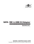
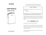
1
RoHS
User's Manual
Package Contents:
EZ SWAP 4 – Removable Hard Drive Rack
1
2
3
4
5
EZ Swap 4
Key
SATA Cable
Installation Screws
User’s Manual
1
2
3
4
SATA
SATA
5
*All other third-party brands and names are the property of their respective owners.
Table of Contents:
1. Introduction
03
2. Features /Specifications
04
3. System Requirements
05
4. Parts Layout
06
5. Installation
07
6. Installing a Hard Drive
09
7. LCD Display
10
8. Warranty / Contact
11
Table of Content
1
Microsoft Windows 2000/XP/Vista/7
Intel PentiumII 350 MHz-compatible
/7
Microsoft Windows 2000/XP/VISTA/7
Mac G3 processor & greater.
MAC OS 8.6 or greater
1. SATA-equipped system.
2. For SATA speeds, the system must
support SATA specifications.
1. SATA-equipped system.
2. For SATA speeds , the system must
tions.
System Requirements
5
4. Parts Layout
EZ SWAP 4 – Removable Hard Drive Rack
Lock
Door
LCD Display
Screws hole
Fan Control
Power port
SATA port
Fan
Parts Layout
6
5. Installation
EZ SWAP 4 – Removable Hard Drive Rack
Power down the computer and disconnect
the power cable.
(Figure 5-A)
(Figure 5-A)
2. Dismantle the left & right side of PC cover.
(Figure 5-B)
(Figure 5-B)
3. Dismantle the front cover of PC.
(Figure 5-C)
(Figure 5-C)
4. Insert the EZ Swap 4 into the 5.25" bay of the
computer. (Figure 5-D)
(Figure 5-D)
Installation
7
5. Tighten the screws to ensure EZ Swap 4 is secure
to the case. (Figure 5-E)
(Figure 5-E)
6. Plug one side of SATA cable into a SATA port on
the motherboard, plug the other side into the
EZ Swap 4. (Figure 5-F & 5-G)
SATA
(Figure 5-F)
7. Connect the 4 pin power cable to the EZ Swap 4's
power connector. (Figure 5-G)
Power Cable
SATA Cable
(Figure 5-G)
8. Reassemble the case and reconnect the power
cable of the computer. (Figure 5-H)
(Figure 5-H)
Installation
8
6. Installing a Hard Drive
EZ SWAP 4 – Removable Hard Drive Rack
1. Use the key to unlock the EZ Swap 4 and then
open the panel. ( Figure 6-A )
( Figure 6-A )
2. Insert the SATA hard drive. ( Figure 6-B )
( Figure 6-B)
3. Close the panel. ( Figure 6-C )
( Figure 6-C )
4. Use the key to lock the EZ Swap 4 to fully activate
the EZ Swap 4. ( Figure 6-D )
NOTE :
EZ Swap 4 has a power security function. When
there is no hard drive present, the EZ Swap 4 will
not power on.
( Figure 6-D )
Instruction
9
7. LCD Display Function
Temperature Display
Thermometer
Fan State Indicator
HDD Indicator
Fan RPM
Fan Settings
Thermometer
When critical temperatures are reached, the thermometer will flash.
Fan State Indicator
When the fan is functioning properly, the fan state indicator will have a spinning
motion. When the fan is working improperly, the fan state indicator will flash.
Temperature Display
Temperature of the hard drive will be displayed in either ℃ and ℉.
(Press “Button + “ and “ Button - “ at the same time to switch between ℃ or ℉ state.)
Fan RPM
This displays current RPM of your fan.
Fan Settings
There are three choices. L (Low speed/2300RPM) ,
M(Medium speed/3600RPM), H(High speed/4500RPM).
HDD Indicator
When a hard drive is inserted, the HDD indicator will be lit. Activity is
shown by flickering or flashes.
Button +
To increase the fan speed.
Button -
To decrease the fan speed.
NOTE :
When the temperature is over the critical safe levels of (55 ℃ // 131℉ )
or if the fan is working improperly, an alarm will sound for 10 seconds
and can be muted by pressing any of the fan control button. The alarm
will ring every 30 minutes until the problem is resolved.
LCD Display Function
10
8. Warranty / Contact
The EZ SWAP 4 comes with a 1 year limited
warranty (90 day parts). If your unit should
become defective within that time frame, please
go to http://www.vantecusa.com for information
on how to receive warranty exchange or repair.
Cosmetic defects and missing parts are not
covered under this warranty.
Please check the contents of the unit to make sure
you received all parts. Also, check for any cosmetic
fla ws. If any parts are missing or if there are
cosmetic defects, please contact theretailer from
which you purchased the unit immediately and
ask for a replacement.
Vantec Thermal Technologies
43951 Boscell Rd.
Fremont, CA 94538
tel: 510-668-0368
fax: 510-668-0367
website: www.vantecusa.com
Copyright © 2009 Vantec Thermal Technologies. All Right Reserved.
All Registered Trademarks Belong To Their Respective Companies.
Warranty / Contact
11