1
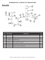
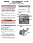
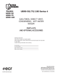
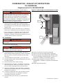
CONDENSATION / EXHAUST KIT INSTRUCTIONS
Kit #550002946
Replacement kit for 90-200 BOILER
Kit installation shall be completed by qualified agency.
! WARNING
Fire, explosion, asphyxiation and electrical shock hazard.
Improper installation could result in death or serious injury.
Read this instruction and understand all requirements,
including requirements of authority having jurisdiction,
before beginning installation. Installation not complete until
appliance operation verified per Installation, Operation &
Maintenance Manual provided with boiler.
•Instructions are for replacing the exhaust tee and
condensate trap assembly with drain exiting bottom of
the exhaust tee on the 90-200 boiler allowing boiler to
properly drain.
Figure 1 - Exhaust Pipe and Condensation Line Cuts
CUT A
5-1/2”
•Particulate will collect in the drain plug on exhaust tee.
Drain plug on exhaust tee can be removed for cleaning.
•Follow instructions TO TURN OFF GAS TO APPLIANCE
found on Operating Instructions label on boiler or in
Installation, Operation & Maintenance Manual. Verify all
electrical power to boiler is turned off.
Kit Installation:
CUT C
CUT B
! WARNING
Electrical shock hazard. Turn OFF electrical power supply at
service panel.
1. Remove front jacket panel(s).
! WARNING
Burn hazard. Verify heat exchanger has cooled or use
appropriate personal protection equipment.
2. Cut exhaust pipe 5½" from tee flange. See figure 1.
3.
4.
5.
6.
7.
8.
9.
Before cutting vertical exhaust pipe, verify it is secured
and will not fall. Cut existing exhaust pipe and edge.
See Cut A.
Cut condensation line just below ½" tee. See Cut B.
At boiler exhaust outlet, loosen downstream pipe clamp
on rubber coupling.
Remove assembly from rubber coupling.
Assemble parts 1 through 3. Thread item 4 onto tee.
Slide coupling onto existing exhaust pipe. Insert other
end into rubber coupling at boiler's exhaust outlet.
Assemble remaining kit parts. See Figure 2. Assemble
drain piping then attach assembly to threaded fitting in
exhaust tee. See item 4.
Cut existing condensate lines. Use new parts as guide
for measuring where to cut remainder of existing
condensation line pipes. See Cut C.
Connect existing line with new ½" condensate line
coupling.
10. Verify all joints are air-tight and cemented.
11. Verify hose clamp at exhaust outlet is tightened.
12. Resume operation using OPERATING INSTRUCTIONS
found on Operating Instructions label on boiler or in
Installation, Operation & Maintenance Manual.
13. Verify proper operation by following START UP
PROCEDURE in Installation, Operation & Maintenance
Manual.
14. Install front jacket panel(s).
P/N 240010634 Rev. A [06/2014]
CONDENSATION / EXHAUST KIT INSTRUCTIONS
Figure 2 - Kit Parts
1
2
10
7
7
7
11
3
6
2
4
8
7
5
7
12
8
8
7
PARTS LIST FOR KIT 550002946
ITEM
PART NUMBER
DESCRIPTION
QTY
1
240006822
Coupling, 2” CPVC
1
2
240006827
Vent Pipe, 2” Sch. 40 x 7” long CPVC
2
3
3002223
Tee, 2” Sch 80 CPVC
1
4
14631301
2 3/8” ID Hose, 3” long
1
5
240005852
PVC Cleanout Cap
1
6
1001002
PVC Fitting, 1/2”NPT Male x 1/2” Slip Female
1
7
240007262
Pipe, 1/2” Sch. 40 x 3-3/4” PVC
6
8
1190005
Elbow, 1/2” x 90° Sch. 40 PVC
3
10
240007251
Coupling, 1/2” Sch. 40 PVC
1
11
1510015
Tee, 1/2” x 1/2” x 1/2” Sch. 40 PVC
1
12
14631302
Stainless steel clamp
2
Check our website frequently for updates: www.ecrinternational.com