1
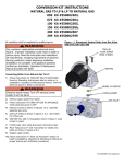
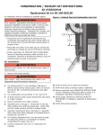
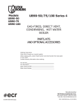
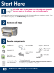
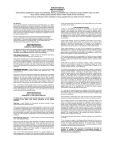
SERIES 2 – Q3452 Spark Pilot Retrofit
KIT# 550002585
INSTALLATION INSTRUCTIONS
! WARNING
Fire, explosion, asphyxiation and electrical shock
hazard. Improper installation could result in death or
serious injury. Read this instruction and understand
all requirements, including requirements of authority
having jurisdiction, before beginning installation.
Installation not complete until appliance operation
is verified per Installation, Operation & Maintenance
Manual provided with boiler.
This kit is for both natural gas and LP versions. Pilot is
shipped for natural gas, a conversion package is included in
this kit.
Following instructions for installation of Q3452 Spark Pilot
Retrofit Kit for Series 2 Boilers.
Kit# 550002585 Contents
Qty
Natural Gas spark/standing pilot assembly
1
Pilot Assembly Mounting Screws
2
Gas Valve Compression Fitting
1
LP Pilot Orifice
1
Figure 1 - Base Front (3 Section Shown)
Burner
Door
Pilot
Mounting
Screws
1. Follow instructions to TURN OFF GAS TO APPLIANCE
found on Operating Instructions label on boiler or in
Installation, Operation & Maintenance Manual. Verify all
electrical power to boiler is turned off.
! WARNING
Lower
Front
Panel
Burner
Tubes
Electrical shock hazard. Turn OFF electrical power
supply at service panel.
2. Allow boiler to cool for 30 minutes before starting
installation.
! WARNING
Burn hazard. Verify heat exchanger and igniter
have cooled or use appropriate personal protection
equipment before removing pilot.
Figure 2 - Bend Pilot Tubing (Shield Not Shown for
Clarity)
3. Remove front boiler door.
4. Disconnect spark cables from control board.
5. Disconnect pilot tube from gas valve. Loosen
compression fitting located on top of gas valve.
6. Locate current pilot assembly in front of base. See
7.
8.
9.
10.
Figure 1.
Remove top burner door and burner tubes.
Remove two pilot mounting screws holding pilot
assembly in place. Remove entire pilot assembly.
If this is LP Boiler, convert pilot to LP configuration
using enclosed pilot orifice.
This step is for 2 section boiler only. Remove pilot
assembly from box. Bend pilot tubing as shown in
Figure 2 (tight 180º, then 90º back) in order to get it in
between upper and lower burner doors.
P/N 240009742 Rev. A [08/2012]
KIT INSTALLATION INSTRUCTIONS
! WARNING
Figure 3 - Install Pilot Assembly
Fire, burn hazard. Do not operate boiler without
burner doors in place. Failure to follow these
instructions could result in death or serious injury.
NOTE: Refer to Figure 6 final pilot tubing configuration.
11. Remove pilot assembly from box. Spin assembly so it
enters base between lower front panel and top of base.
See Figure 3.
12. Push assembly into base. If needed, slide pilot tube
and spark wire (or thermocouple) through hole in lower
front panel. See Figure 4.
13. Rotate pilot assembly until it is vertical and holes in
pilot assembly line up with pilot mounting holes in
top of base. Verify base insulation is over top of pilot
bracket, not in between bracket and base top. See
Figure 5.
14. Fasten assembly using screws provided. After
fastening assembly, reach in base above bracket and
verify insulation is laying flat against base front.
15. Verify pilot assembly is correctly angled; at right angle
with top of base.
16. Install burner tubes in base by sliding crimped end into
slots in back of base. Rest front of burner on orifices.
Replace upper burner door. See Figure 5.
17. Final pilot tubing configuration after completion all
steps see Figure 6.
18. Refer to Installation, Operation and Maintenance
Manual and labels affixed to boiler for lighting
instructions.
Figure 4 - Installed Pilot Assembly (3 Section Shown)
Figure 5 - Install Burner Door and Tubes
(3 Section Shown)
Figure 6 - Series 2 Final Pilot Tubing Configuration
(2 Section Shown)
ECR International, Inc.
2201 Dwyer Avenue, Utica NY 13504-4729
web site: www.ecrinternational.com