1
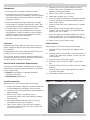
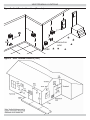
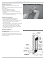
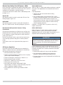
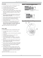
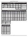
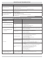
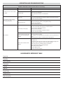
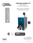
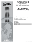
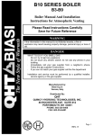
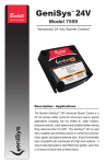
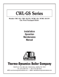
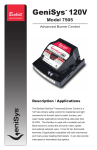
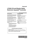
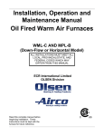
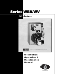
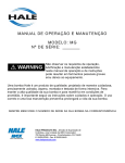
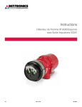
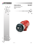
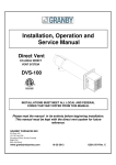
SUPPLEMENTAL INSTRUCTIONS:
DIRECT VENT
INSTRUCTIONS FOR HIGH EFFICIENCY OIL-FIRED
HOT WATER BOILER
Information contained in this manual pertains to direct vent
boilers equipped with manufacturer installed blocked vent
safety control system (pressure switch).
! WARNING
Installations of venting shall be done only by a
qualified expert and in accordance with these
instructions. Venting a boiler or any other oil
appliance with improper methods or materials may
result in serious injury or death due to fire or to
asphyxiation from poisonous gases such as carbon
monoxide which is odorless and invisible.
Keep area around vent terminal free of snow, ice, and
debris.
Direct Venting Of Oil Fired Boilers ..................................................................................... 2
Vent Terminal Locations ................................................................................................... 3
Vent Terminal Installation ................................................................................................ 4
Intake Air Pipe Installation ............................................................................................... 5
Vent Pipe Installation ...................................................................................................... 6
Blocked Vent Safety Shutoff System.................................................................................. 7
Sequence Of Operation ................................................................................................... 8
Final Check Out .............................................................................................................. 9
Burner Settings Tables .................................................................................................. 10
Burner Settings Tables .................................................................................................. 11
Wiring Diagrams........................................................................................................... 12
Operation And Troubleshooting ....................................................................................... 14
P/N# 240009355, Rev. B [08/2012]
DIRECT VENTING OF OIL FIRED BOILERS
Introduction
F. Less than 1 foot (0.3m) above grade level within
6 feet (1.80m) of any combustion air inlet, unless
appliance is otherwise certified.
G. Within 6 feet (1.80m) of property line.
H. Underneath veranda, porch, or deck.
I. So the flue gases are directed at combustible material
or at any openings of surrounding buildings that are
within 6 feet (1.80m).
J. Less than 3 feet (1m) from inside corner of L-shaped
structure.
K. So the bottom of the vent termination opening is
less than 1 foot (0.3m) above any surface that may
support snow, ice, or debris.
L. So the flue gases are directed towards bricks, siding,
or other construction, in such a manner that may
cause damage from heat or condensate from flue gas.
M. Within 4 feet (1.2m) of power venter.
• Direct Vent refers to sealed combustion system.
• Direct Vent series is ideal for applications where a
conventional chimney is unavailable, not easily installed;
electrically heated home being retrofit for oil forced air
heating for example.
• Direct vented appliances require planning, the range
of flue lengths is restricted, clearances are critical, and
national and local codes are strict with respect to safety.
• Be sure the Boiler can be installed within homes
physical limitations, and accordance with local codes
and regulations. Physical limitations include sufficient
clearance to grade. Avoid vent termination locations
subject to frequent strong wind gusts.
• See Table 1 for approved venting.
Oil Burners
USA Installation
Beckett NX and Riello’s 40BF series Oil burners, are certified for venting through the wall using ducted outdoor air
for combustion.
Refer to figure 3, vent terminal shall not terminate:
A. Less than 7 feet (2.13m) above any adjacent public
walkway.
B. Less than 4 feet (1.22m) below, 4 feet horizontally, or
1 foot (0.3m) above door, window, or gravity air inlet
of the structure.
C. Less than 1 foot (0.3m) above grade.
D. Less than 1 foot (0.3m) from soffit or roof of structure.
E. Less than 3 feet (0.9m) from inside corner of L shaped
structure.
F. Less than 5 feet (1.6m) of gas regulator vent outlet,
or oil tank vent outlet.
G. Underneath veranda, porch or deck.
Standard Beckett AFG Series and Riello 40F Series are not
certified for use, in direct vent applications.
The oil burner contains a probe to measure overfire pressure and a pressure switch which does not permit burner to
operate if intake or exhaust are blocked.
Vent Terminal Installation Requirements
Through the wall termination installation shall conform to
requirements of authority having jurisdiction or in absence
of such requirements
• Canada Current Edition of Canadian Standards
Association CSA B139,
• United States ANSI/NFPA 31.
Figure 1 - Standard Vent Terminal Assembly
Canadian Installation
Refer to figure 2, vent terminal shall not terminate :
A. Directly above paved sidewalk or paved driveway that
is located between two buildings, and serves both.
B. Less than 7 feet (2.13m) above any paved sidewalk or
paved driveway.
C. Within 6 feet (1.80m) of a window, door, or
mechanical air supply inlet to any building, including
soffit openings.
D. Above gas/regulator assembly within 3 feet (1m)
horizontally of center-line of regulator.
E. Within 6 feet (1.80m) of any gas service regulator
vent outlet or within 3 feet (1m) of any oil tank vent
or any oil tank fill inlet.
2
VENT TERMINAL LOCATIONS
Figure 2 - Vent Terminal Locations (Canada)
C
C
J
C
C
M
D&E
B
Forced air
inlet
F&K
Figure 3 - Vent Terminal Location (USA)
3
VENT TERMINAL INSTALLATION
Vent Terminal Location
Figure 4 - Inside View of Vent Terminal
See table 1 for equipment certified for use with this
appliance.
Select location of wall penetration that conforms to code for
exterior location:
1. As close to appliance as possible,
2. Maintains clearance to combustibles,
3. Maintains minimum 1/4 inch per foot slope back to
appliance.
4. Install vent terminal in wall having minimum thickness
of 5”, and maximum thickness of 10”.
Vent Terminal Installation
• Cut a 6-1/2” diameter hole through the wall.
• Remove Intake Air Sleeve from Terminal.
• Insert Terminal through the wall from outside, secure
with 4 screws to the wall, and seal to wall with
weatherproof sealant.
• From inside the building, re-attach Intake Air Sleeve and
secure inner sleeve to outer sleeve with 2 screws.
• Use 4 screws to secure Sleeve to wall. See Figure 4.
• Insure Intake Air Connector is located for easy attachment and complies with code.
Vent Terminal Riser Kit
Figure 5 - Vent Terminal Riser
Kit is designed to increase height of vent terminal by
approximately 3 feet.
Ideal where excessive snow build up could occur or where
more flexibility is required to maintain minimum clearances
at grade. See figure 5.
4
INTAKE AIR PIPE INSTALLATION
Direct Vent Intake Air Pipe Installation
Do not use Flexible duct for combustion air.
Outdoor air for combustion must be used.
Oil burners approved for use with outdoor air for combustion are Beckett NX and Riello 40BF.
Outdoor air is obtained using the following materials/
methods.
Acceptable combustion air intake materials are listed below.
Beckett NX Burner :
• 4 inch “C” Vent (single wall galvanized).
• 4 inch Rigid Aluminum pipe (0.030” wall thickness).
Riello 40BF Burner :
• 4 inch “C” Vent (single wall galvanized).
• 4 inch Rigid Aluminum pipe (0.030” wall thickness). Use
4 inch pipe from the terminal to appliance. Reduce to 3
inch pipe to attach to burner inlet collar.
NOTICE
Seal intake pipe and fittings with foil tape, duct
tape, or silicone caulking and attached mechanically
with screws.
Maximum combustion air intake length is 25 feet using
eight 90° elbows. Combustion air intake does not have
minimum length.
Condensation may become a concern during some climatic
conditions. It may be necessary to wrap a portion, or
entire intake piping (particularly metal intake piping) with
waterproof insulation material.
5
VENT PIPE INSTALLATION
Venting Installation - Direct Vent
Figure 6 - Appliance Connector w/ Test Port
! WARNING
Improper installation, adjustment, alteration, service
or maintenance could result in death or serious
injury. Do not enclose vent.
Do not route vent through walls, floors or ceilings.
Venting and vent terminal are dedicated to the Boiler
only; do not attempt to vent any other appliance
through it.
Flexible Vent Installation
Supplied flexible exhaust duct is a double wall, one (1) inch
clearance to combustibles, flexible venting material.
Inner pipe is constructed of 4 inch inside diameter 316
stainless steel, with two-ply aluminum outer pipe.
High temperature insulation separates inner and outer flex
pipes.
Figure 7 - Male End
Vent installation shall conform to requirements of authority
having jurisdiction or in absence of such requirements NFPA
31 Installation Of Oil Burning Equipment (U.S.) or CSA
B139 (Canada) and applicable provisions of local building
codes and these instructions.
! CAUTION
Use appropriate safety precautions. Thin metal
edges are extremely sharp. If not avoided, could
result in minor or moderate injury.
1. In as short and straight a run as possible without any
unnecessary bends.
2. No dips or sags throughout full length of vent.
3. Slope connector or vent upwards from appliance at
least 1/4” per foot.
4. Do not bend connector or vent more than 90°.
5. May cut vent to a minimum of 5 feet in length using
fine tooth (24 teeth per inch) hacksaw blade.
6. Clean male and female ends of the appliance adapters
and connectors with residue free brake cleaner solvent.
7. Apply minimum 1/4” bead of Si-Ultra Copper Sealant
provided, onto outside of male end of vent to appliance
connector. Fit connector to vent by threading it
counter-clockwise until it stops. Insure joint is not
cross-threaded. Tighten gear clamp on outer cover. See
figures 7, 8 & 9.
8. Apply minimum 1/4” bead of same sealant on female
end inside of connector. Slip connector over end of
appliance collar until it stops. Tighten attached gear
clamp. See Figure 8.
9. Support Vent every 36” to prevent sagging.
10. Attach Terminal Connector as described in steps listed
above.
11. Maximum vent length is 20 feet (using 20 foot vent
kit). Piecing vent kits together (i.e. using 2 ten foot
kits) is strictly prohibited.
Figure 8 - Female End
6
BLOCKED VENT SAFETY SHUTOFF SYSTEM
Blocked Vent Safety Shut Off System (BVS)
Beckett NX Burner:
Direct vent Boiler is equipped with Blocked Vent Safety shut
off system (BVS). Safety circuit shuts burner off in event of
combustion air blockage or venting blockage.
Refer to Table 2. Select head setting according to required
firing rate. Final adjustments are required once burner is
started.
It is best to have burner shutter and or head settings close
to Table 2 or 3.
Final Adjustments
• Tighten lock nuts and screws before making
measurements.
• Using suitable testing instruments for CO2 (or O2),
measure combustion products. CO2 in the stack should
be minimum of 12% CO2 at a trace of smoke. For
clean operation of burner, open air control to introduce
enough excess air into the system to reduce CO2 by
10% of original trace point.
EXAMPLE: 12% CO2 minus 1.2 (which is 10% of 12)
equals 10.8% CO2).
Beckett NX
BVS pressure switch is wired in series with CAD cell. See
Wiring Diagram, Figure 12.
Riello 40BF
BVS pressure switch is wired in series with terminals 10
and 11 on 530SE control. See Wiring Diagram, Figure 13.
Riello 40BF Burner:
Blocked Vent Safety Switch Pressure Tubing
Connections
Refer to Figure 10. Check initial air shutter and head
settings. Remove burner cover and turn air shutter
adjustment screw (2) until top edge of air shutter (3) is in
alignment with corresponding number in Table 3.
Check tubing connections on all Boilers prior to firing unit.
Beckett NX has low and high side tube, vacuum side goes
to air intake box, pressure side goes to overfire pressure
probe. See Figure 11.
Riello BF low pressure side is open inside air tight burner
cover and high pressure side goes to overfire pressure
probe.
NOTICE
Riello burner pressure gauge threads are British
Parallel Thread design. Test gauge with NPT fitting
ruins pump body. Use Riello pressure gauge or
adapter.
Verify burner cover is air tight and all hole plugs are in
place.
Further adjustments must be made with burner cover in
place by unscrewing plug on cover. Turn screw clockwise to
increase combustion air or counter clockwise to decrease
combustion air.
Oil Burner Operation
Once Boiler flue pipe and intake pipe are completely installed. In absence of burner manufacturer’s instructions,
use following instructions to set burner:
• Shutter final position will vary on each installation.
• Use instruments to establish proper settings for
maximum CO2 and smoke spot reading of zero.
• Re-insert plastic cap over air adjustment hole before any
measurements.
• Shut off electrical power to Boiler.
• Install oil pressure gauge to pressure port on oil pump.
(Riello requires special adapter)
• Check air settings for initial firing in Table 2 or 3.
• Restore electrical power to Boiler.
• Start Boiler. Bleed all air from fuel oil lines.
• Close purge valve and fire unit.
• When Boiler has reached “steady state” (after
approximately 5 minutes), remove bolt (test port) from
center of Appliance Adapter to Boiler.
• Set combustion air control to get TRACE to ZERO
smoke.
7
SEQUENCE OF OPERATION
Beckett NX
1.
2.
3.
4.
5.
6.
7.
8.
9.
10.
Figure 9 - Flex Vent Assembly Detail
Room temperature drops, thermostat calls for heat.
Pre-purge begins, lasting 5 to 15 seconds.
Oil solenoid and BVS are energized
Oil Solenoid opens allowing oil to reach Burner
Electrodes. Burner ignition begins.
If vent is clear, pressure switch closes, Cad cell detects
light from combustion the primary control safety circuit
disconnects allowing combustion to continue. BVS is
energized.
After 15 to 45 seconds (depending on primary control
characteristics), electric spark across electrode tips
stops, combustion continues.
Boiler continues operation and reaches “steady state”,
point at which system temperature stabilizes.
Room temperature rises, thermostat is satisfied,
heating contacts open.
Oil solenoid valve closes, combustion stops, burner
motor remains on to complete Post Purge Cycle.
Post Purge time can be 0 to 8 minutes depending on
settings. Factory default is 2 minutes. Timing can be
changed using Beckett 5206 Genisys display.
Boiler remains idle until next call for heat.
Figure 10 - Air Shutter Setting
Riello 40BF
1. Room temperature drops, thermostat calls for heat.
2. Pre-purge begins, lasting 5 to 15 seconds. BVS is
3.
4.
5.
6.
7.
8.
9.
10.
energized.
If flue is clear, pressure switch allows ignition sequence
to continue.
Oil Solenoid opens allowing oil to reach burner
electrodes. Burner ignition begins.
Cad cell detects light from combustion, disconnects
primary control safety circuit, allowing combustion to
continue.
After 15 to 45 seconds (depending on primary control
characteristics), electric spark across electrode tips
stops, combustion continues.
Boiler continues to operate and reaches “steady state”,
the point at which the system temperature stabilizes.
Room temperature rises, thermostat is satisfied,
heating contacts open.
Oil solenoid valve closes, combustion stops, burner
motor remains on to complete post purge cycle. Post
purge time can be 10 seconds to 5 minutes depending
on settings. Factory default is 45 seconds. Timing can
be changed by rotating dial on Riello burner fan-off
timer control board.
Boiler remains idle until next call for heat.
8
FINAL CHECK OUT
• Carefully examine complete vent system for leaks. This
may be done by spraying soapy solution on all joints
and watching for bubbles during pre-purge. The hot vent
can be checked with lit taper for signs of air movement
around joints or seams.
• Insure all safety devices and electrical components
have been set for normal operation. Insure all electrical
connections are tight and wiring is secure.
• Insure homeowner is informed and understands the
following:
1. Where circuit breaker or fuse is located in main
electrical panel.
2. Where Boiler switch is located, and switch “on” and
“off” positions if not obvious.
3. Where oil shut-off valve from oil storage tank is
located.
4. To keep area around vent terminal free of snow, ice,
and debris.
5. How to operate the thermostat, and other related
accessories.
6. How to operate manual reset button on primary
control, and especially when not to push the reset
button.
7. How and where to visually inspect the venting system
for leaks or other problems.
8. How to inspect, clean and replace the air filter, and
other homeowner maintenance procedures.
9. Who to call for emergency service and routine annual
service.
10. Terms and conditions of the manufacturer’s warranty
and the contractor’s warranty.
9
BURNER SETTINGS TABLES
TABLE 1: THE HIGH EFFICIENCY OIL BOILER IS CERTIFIED FOR USE ONLY WITH THE FOLLOWING PART
NUMBERS
Items with Boiler
Burner
Options
Item
Part Number
Riello
40BF
4-7/8” to 4” Appliance Adapter
240007535
Beckett
NX
Termination
Options
Part Number
Vent Length
Part number
Options
Field Supplied Items
STD Terminal
28972
4” ID x 10
FT
240006909*
4x3” Single wall Reducer
for Riello
36” Riser
29231
4” ID x 15
FT
240006910*
4” ID x 20
FT
240006911*
Single Wall Vent 25 FT Max
With Up To (8) 90 Deg.
Elbows for Air Intake Pipe
*Includes Terminal Adapter and Caulking p/n 240006914
TABLE 2: BECKETT DIRECT VENT PRELIMINARY BURNER SETTINGS
Pressure
Switch
Setpoint
Rated
AFUE
Efficiency
[%]
1.5
0.65" WC
86.0
155
4.0
0.65” WC
85.0
0.75x45B
175
4.0
0.85" WC
86.5
1.00x60B
140
1.8
0.85” WC
85.0
V5
Delevan 1.10x60B
150
2.5
0.85” WC
84.0
V6
Danfoss
175
2.0
0.65" WC
86.5
Boiler
Model
Head
Type
Insertion
Depth
Firing
Rate
[GPH]
Combustion liner
Nozzle
Mfr.
Nozzle
Type
4075
6 Slot
2.5"
0.75
Oval
Delavan
0.60x60B
150
4095
6 Slot
2.5”
0.95
Oval
Hago
0.75x60B
5100
6 Slot
2.5"
1.00
None
Delavan
5115
6 Slot
2.5”
1.15
V5
Hago
5135
6 Slot
2.5”
1.35
6130
9 Slot
2.5"
1.30
Timings
Pre-purge
15 seconds
Post-Purge
2 minutes
TABLE 2: BECKETT/ECR PART NUMBERS
Boiler
Model
Beckett
Oil Burner
Model
ECR Oil Burner
Part Number
4075
NX70LC
240007531
4095
NX70LC
240009393
5100
NX70LC
240007532
5115
NX70LF
240009395
5135
NX70LF
240009396
6130
NX70LD
240007533
10
1.00x45B
Pump
Air
Pressure
Setting
[PSI]
BURNER SETTINGS TABLES
Table 3: RIELLO 40BF DIRECT VENT PRELIMINARY BURNER SETTINGS
Inser- Firing
Comtion
Rate bustion
Depth [GPH] Liner
Nozzle
Mfr.
Nozzle
Type
Pump
Pressure
[PSI]
Rated
Pressure
AFUE
Switch
Efficiency
Setpoint
[%]
Boiler Model
Head
Type
4075
Reverse
2.75"
0.75
Oval
Delavan
0.65x60W
150
3
5.0
0.25" WC
86.0
4095
Standard
1.75"
0.95
Oval
Delavan
0.75x90B
175
1
4.0
0.25" WC
85.0
4110
Standard
1.75"
1.10
Oval
Delavan
1.00x90B
125
2
5.0
0.25" WC
84.0
5100
Standard
2.75"
1.00
None
Delavan
0.75x60B
175
1
5.0
0.80" WC
86.5
5115
Standard
1.75"
1.15
None
Delavan
1.00x80B
130
2
5.8
0.80” WC
85.0
5135
Standard
1.75"
1.35
None
Delavan
1.20x80B
125
4
5.8
0.80” WC
84.0
6130
Standard
2.75"
1.30
V6
Delavan
1.00x45B
175
2
8.0
0.90" WC
86.5
Timings
Pre-purge
12 seconds
Post-Purge
45 seconds
Riello
Boiler
Oil
Model Burner
Model
ECR Oil Burner
Part Number
4075
40BF3
240007528
4095
40BF5
240009407
4110
40BF5
240009408
5100
40BF5
240007529
5115
40BF5
240009409
5135
40BF5
240009410
6130
40BF5
240007530
11
Head
Air
Setting Setting
WIRING DIAGRAMS
Figure 11 - Beckett NX With Blocked Flue Pressure Switch Safety
Figure 12 - Wiring Diagram: Beckett NX With GenisysTM 7505 (15 Seconds pre purge, 2 minutes post
purge)
(BLUE/WHITE)
(WHITE)
(ORANGE)
(WHITE)
(BLACK)
(RED)
(WHITE)
(VIOLET)
(WHITE)
(YELLOW)
12
WIRING DIAGRAMS
Figure 13 - Riello Wiring Diagram With Post Purge Timer And Blocked Flue Pressure Switch
Safety
If a neutral or ground lead is attached to terminal 4, the CONTROL BOX
on the burner will be damaged should lockout occur.
13
OPERATION AND TROUBLESHOOTING
NX Burner With Blocked Vent Safety (BVS) Operation
External Action
Appliance Response
Power applied to burner control
Internal safety check conducted. If no light or flame is detected and all internal conditions are correct,
control enters idle mode.
Thermostat Calls For Heat
1. Contacts between T and T on Aquastat L7248A are closed.
2. Burner Control period (4 seconds) internal and external check for flame or light. If flame is detected, control remains in
idle mode.
3. When flame is not present, Burner Control will apply power to the burner motor and igniter, complete a 15 second
valve on delay period and then apply power to the oil valve circuit.
4. Burner Control enters the trial for ignition period.
A. Monitors burner for flame.
B. When flame is not detected:
I. Enters lockout mode after 15 seconds.
II. Shuts off valve, igniter and burner motor.
III. Flashes indicator light at 1 Hz (½ second on, ½ second off).
IV. Depress reset button to return to power up sequence.
C. When flame is detected, Carry-Over period begins:
5. Burner Control enters 10-second Ignition Carry-Over period.
A. Turns on indicator light
B. If flame is lost and lockout time has not expired, Burner Control returns to trial for Ignition period.
C. If flame is lost and lockout time has expired, Burner Control enters Recycle Mode.
6. Carry-over time expires and igniter turns off.
7. Enters a run mode:
A. Flame is monitored until call for heat ends or flame is lost. If flame is lost:
B. Control enters Recycle Mode.
I. Recycle time starts (60 seconds).
II. Burner and valve are turned off.
III. Indicator light flashes at ¼ Hz (2 seconds on, 2 seconds off).
Call for heat is satisfied.
Reset button pushed two times
without device completing a call for
heat.
IV. Returns to Idle mode at end of Recycle mode.
1. Oil valve circuit is de-energized and valve shuts off.
2. Burner motor runs for selected post purge time.
3. Burner motor turns off.
4. Burner Control returns to Idle mode
1. Burner Control enters restricted mode.
2. Indicator light flashes 1 Hz (½ second on, ½ second off).
3. Reset device by pressing and holding reset button for a minimum of 45 seconds.
GeniSys 7505 Reset Button Operations
Pushing the reset button in the current state will cause the following conditions:
If the burner state is:
Pushing the reset button < 1 second
Lockout
Pushing the reset button > 1 second
Reset from Restricted (Hard)
Lockout
Reset from Soft Lockout
Valve On Delay, Trial For
Ignition, Ignition Carryover
Run (igniter is shut off)
Pump Prime
Yellow light flashes to indicate cad cell
resistance.
Motor-Off Delay, Standby
No action
Pump Prime
No action
Disable the Burner. Any time the
burner is running, press and hold the
reset button to disable the burner. The
burner will remain off as long as the
button is held.
Enables pump priming: After the
reset button has been held for 15
seconds the button can then be
clicked during the next ignition
sequence to enter pump prime
mode.
Exit pump prime mode and return to standby.
Status Lights
Light Color
Push, hold reset button >15
seconds
On Continuously
Flashing
Red
Restricted (Hard) Lockout
Soft Lockout
Green
Flame Sense during normal operation.
May be stray light during standby.
Recycle
Yellow
Control is in Pump Prime mode OR
reset button is currently held for >15
seconds.
Cad cell resistance.
14
OPERATION AND TROUBLESHOOTING
Beckett NX BURNER TROUBLESHOOTING
Condition 1: Burner motor does not start when there is a call for heat.
Procedure
Status
Corrective Action
1. Check that limit switches are closed and
contacts are clean.
N/A
N/A
2. Check for line voltage power at the oil
primary control. Voltage should be 120
Vac between the black and white lead
wires on the oil primary control.
N/A
N/A
3. Check indicator light with burner off, no
call for heat (no flame).
4. Shield cad cell from external light.
5. Verify that the oil valve is closed during
the valve on delay period by observing the view port and verifying that no
flame is present during the 15-second
valve on delay .
Green Indicator light
is on.
Cad cell is defective, sees external light, or connections have shorted. Go to step
4.
Green Indicator light
is off.
Go to step 6.
Green Indicator light
turns off.
Eliminate external light source or permanently shield cad cell.
Green Indicator light
stays on.
Replace cad cell with new cad cell and recheck.
If indicator light does not turn off, remove cad cell lead wires from Aquastat and
recheck.
If indicator light is still on, replace the Aquastat control.
If the indicator light turns off, replace cad cell bracket assembly.
Green Indicator light
is on.
If flame is present, replace the oil valve.
Burner starts.
Trouble is in thermostat circuit. Check thermostat-wiring connections.
If connections are clean and tight, check thermostat wires for continuity.
6. Jumper thermostat (T -T) terminals on
Aquastat
IMPORTANT
First remove one thermostat lead wire.
Burner does not start.
•
Disconnect line voltage power and open line switch.
•
Check all wiring connections.
•
Tighten any loose connections and recheck.
•
If burner still doesn’t start, replace Aquastat.
If burner still doesn’t start, check the oil burner motor. It may be seized or
burned out.
15
OPERATION AND TROUBLESHOOTING
Condition 2: Burner starts then locks out on safety with red indicator light flashing.
Procedure
1. Reset oil primary control by pushing in and releasing
red reset button.
2. Listen for spark after burner turns on (after 2 second
delay).
3. Check indicator light after flame is established, but
before oil primary control locks out.
4. Check cad cell sighting for view of flame.
• Disconnect line voltage power and open line switch.
• Unplug cad cell and clean cad cell face with soft clothe.
Check sighting for clear view of flame. Replace cad
cell in socket.
• Reconnect line voltage power and close line switch.
• Start burner.
5. Check cad cell.
• Disconnect line voltage power and open line switch.
• Remove existing cad cell and replace with new cad cell.
• Disconnect all wires from thermostat terminals to
ensure that there is no call for heat.
• Reconnect line voltage power and close line switch.
• Expose new cad cell to bright light such as a flashlight.
6. Check cad cell bracket assembly.
• Disconnect line voltage power and open line switch.
• Remove cad cell wires from quick connect connectors
on the Aquastat and leave control lead wires open.
• Apply power to device.
• Place jumper across cad cell terminals after burner
motor turns on.
Status
Corrective Action
Indicator light stops
flashing.
Go to Step 2.
Indicator light
continues to flash at
1/2 second on, 1/2
second off rate.
Verify that the control is not in restricted mode. (See notes at end of this
table.). If not in restricted mode, replace Aquastat
Ignition is off
Spark igniter could be defective. Check for line voltage at igniter
terminals. If line voltage is present, replace R7484.
Ignition is on.
Go to Step 3.
Ignition is on but no
oil is being sprayed
into the combustion
chamber.
Wait for “Valve ON” delay to complete.
Check oil supply.
Ensure BVS bypass contact close and bypass pressure switch for
10-seconds.
After 10-seconds, check pressure switch on BVS to ensure closed.
Pressure switch open.
Check pressure tubes for proper connection or possible obstructions.
Check venting for blockage.
Check combustion air intake for blockage.
Check pressure switch operation.
Check oil line valve.
Check for filter blockage or seized oil pump.
Indicator light is
on until the control
locks out and starts
flashing during
lockout.
Check Aquastat
Indicator light stays
off.
Go to step 4.
Burner locks out.
Go to step 5.
Burner keeps
running.
System is OK.
Indicator light is on.
Remount control onto burner housing. Go to step 6.
Indicator light is off.
Go to step 6.
Indicator light is on.
Replace cad cell bracket assembly.
Indicator light is off.
Replace Aquastat.
NOTE: Restricted Mode - (Limited Reset): In order to limit the accumulation of unburned oil in the combustion chamber, the control can be reset only
3 times, after which, the control locks out. The reset count returns to zero each time a call for heat is successfully completed.
To reset from Restricted Mode: press and hold the reset button for 30 seconds. When the LED flashes twice, the device has reset.
NOTE: Disable function: Pressing and holding the reset button will disable all functions until the button is released. The burner will restart at the
beginning of the normal heat cycle on safety check.
16
OPERATION AND TROUBLESHOOTING
Beckett NX: System and General Troubleshooting
Problem
Boiler will not start.
Boiler will not start without
first pushing oil primary
control reset button.
(Happens on frequent basis)
Boiler starts, but cuts out
requiring manually resetting
the oil protector reset button
Possible Cause
Remedy
Thermostat not calling for heat.
• Check thermostat and adjust. Also, check thermostat for accuracy; if it is a mercury
switch type, it might be off level.
No power to Boiler.
• Check Boiler switch, main electrical panel Boiler fuse or circuit breaker. Also look for any
other hand operated switch, such as an old poorly located Boiler switch, which was
not removed during Boiler replacement.
Thermostat faulty.
• Remove thermostat wires from control terminals T-T. Place a jumper across T-T. If Boiler
starts, replace thermostat, thermostat sub-base (if equipped), or both.
Oil primary control faulty.
• Check reset button on oil primary control.
Photo Cell wiring shorted or
room light leaking into photo cell
compartment
• Check photocell (cad cell) wiring for short circuits. Also, check for room light leaking
into cad cell compartment. Repair light leak if necessary. See Table C-3.
Open safety switch.
• Check for open limit or auxiliary limit. Also, check internal wiring connections; loose
connectors, etc.
Photo Cell (Cad Cell) defective.
• If call cell is dirty, clean it. (Determine why cad cell is getting dirty). If cad cell is poorly
aimed, realign it. NOTE: The photocell should have a resistance of 100KΩ in absence
of light; a maximum of 1500Ω in the presence of light. Ensure that room light is not
leaking into the cad cell compartment. (See diagnostic light section).
No fuel oil.
• Check fuel oil supply. Check that all hand operated fuel oil valves are in the open position. Fill oil storage tank if necessary.
Clogged nozzle.
• Replace nozzle with high quality replacement. Use rating plate or Tables in Appendix A
as a guide.
Clogged oil filter.
• Replace oil tank filter or in-line filter if used.
Blocked Vent Safety Circuit opening.
• Pressure switch open:
• Check pressure tubes for proper connection or possible obstructions.
• Check venting for blockage.
• Check combustion air intake for blockage.
• Check pressure switch operation.
Low oil pump pressure.
• Connect pressure gauge to oil pump. Adjust pump pressure, or replace oil pump if necessary. Ensure that erratic pressure readings are not caused by defective fuel oil line.
Air getting into fuel oil lines, or fuel
oil line dirty, clogged, or in some
manner defective.
• Check fuel oil lines. Replace any compression fittings found with high quality flared
fittings. Check for any signs of oil leaks. Any oil leak is a potential source of air or
contaminants.
Defective burner motor.
• Check burner motor. If burner motor is cutting out on over-load, determine why.
Replace if necessary.
No fuel oil.
• Check fuel oil supply. Check that all hand operated fuel oil valves are in the open position. Fill oil storage tank if necessary.
Clogged nozzle.
• Replace nozzle with high quality replacement. Use rating plate or Tables in Appendix A
as a guide.
Clogged oil filter.
• Replace oil tank filter or in-line filter if used.
Blocked Vent Safety Circuit opening.
• Check pressure switch on BVS to ensure closed.
• Pressure switch open.
• Check pressure tubes for proper connection or possible obstructions.
• Check venting for blockage.
• Check combustion air intake for blockage.
• Check pressure switch operation.
Low oil pump pressure.
• Connect pressure gauge to oil pump. Adjust pump pressure, or replace oil pump if necessary. Ensure that erratic pressure readings are not caused by defective fuel oil line.
Air getting into fuel oil lines, or fuel
oil line dirty, clogged, or in some
manner defective.
• Check fuel oil lines. Replace any compression fittings found with high quality flared
fittings. Check for any signs of oil leaks. Any oil leak is a potential source of air or
contaminants.
Defective burner motor.
• Check burner motor. If burner motor is cutting out on over-load, determine why.
Replace if necessary.
Water or contaminants in oil.
• Drain fuel oil storage tank, replace fuel oil. (Consult with fuel oil supplier).
17
OPERATION AND TROUBLESHOOTING
Beckett NX: System and General Troubleshooting
Problem
Oil burner sputtering at nozzle
Excessive fuel oil consumption.
Too much smoke.
Soot building up on blast tube (end
coning).
Boiler will not warm home to desired
temperature.
Home does not heat evenly
Possible Cause
Remedy
Electrodes out of adjustment or
defective.
• Check electrode settings. Check electrodes for dirt build-up or cracks in
porcelain.
Poor transformer high voltage
connections or defective
transformer.
• Check contacts between the igniter and electrodes. If OK, replace the igniter
Fuel oil filter clogged.
• Replace fuel oil storage tank filter and / or fuel oil in-line filter.
Defective oil pump.
• Check burner motor / fuel oil pump coupling. Check oil pump pressure.
Replace fuel oil pump if necessary.
Fuel oil line partially clogged or
contains air.
• Bleed air from oil line. If problem persists, replace oil line.
Blocked Vent Safety Circuit
opening intermittently. (Boiler
lights, then turns off)
• Check pressure switch on BVS to ensure it remains closed.
• Pressure switch open.
• Check pressure tubes for proper connection or possible obstructions.
• Check venting for blockage.
• Reduce burner head opening.
• Check combustion air intake for blockage.
• Check pressure switch operation.
Fuel oil leak.
• Check fuel oil line for leaks. Repair or replace if necessary.
Thermostat improperly adjusted or
in poor location.
• Check thermostat heat anticipator setting against measured amperage draw.
Increase heat anticipator setting if necessary. If the thermostat is being
influenced by drafts, sunlight, duct work, etc., relocate to more suitable
location.
Insufficient combustion air
adjustment at oil burner, or
improper draft pressure.
• Check CO2. Should be 11.5% to 12%
Heat exchanger partially clogged.
• Check for soot build-up in heat exchanger flue passages, especially in the
outer radiator.
Flame impingement caused by
Incorrect nozzle angle.
• Check nozzle size and angle. (See Appendix A). Check distance from head to
inside surface of the fire pot.
Thermostat adjustments or
location.
• Check thermostat heat anticipator setting against measured amperage draw.
Increase heat anticipator setting if necessary. If the thermostat is being
influenced by drafts, sunlight, duct work, etc., relocate to more suitable
location.
Insufficient water flow.
• Check all registers.
Defective high limit control.
• Test high limit function of all limit switches. Use a duct thermometer to assess
accuracy of limit control. Replace control if necessary.
Under-sized nozzle.
• Check nozzle and nozzle filter for dirt.
Burner motor stopping
intermittently on overload.
• Check burner motor. Pressure switch opening due to blocked vent. Replace if
necessary.
Improper distribution of heat.
• This is not likely to be a Boiler problem. Balance duct system.
18
OPERATION AND TROUBLESHOOTING
Riello 40BF blocked vent safety (BVS) Operation
External Action
Appliance Response
Thermostat calls for heat.
• Burner enters pre-purge.
• After pre-purge, oil valve is energized and burner lights off.
• Burner operates in run mode.
• Normally closed pressure switch monitors for vent or combustion air intake blockage.
Call for heat is satisfied.
• Oil valve circuit is de-energized and valve shuts off.
• Burner motor runs for duration of burner motor-off delay.
• Burner motor turns off.
Pressure switch contacts open and
cause burner to re-cycle.
1. Check for vent blockage.
2. Check for combustion air intake blockage.
3. Ensure pressure tubes are connected properly and clear of obstructions.
4. Check burner set up.
RIELLO 40BF BURNER TROUBLESHOOTING
Condition: Thermostat is calling for heat. Burner is not running.
Problem
Reset control box.
1. Test for 120 Vac supply at sub-base between L (P) & N or terminals #3 and #5.
2. Turn off power supply- Remove control
box and jumper terminals #5 and #6.
Restore power.
3. Burner Starts
4. Burner Runs, post purge successful.
Aquastat Shows Error EE4.
Possible Cause
Remedy
Burner starts.
Go to step #3
Burner does not start
Go to step #1
120 Vac present.
Go to step #2
No voltage
• Check system fuse, breaker or ensure service switch is ON.
• Verify all limits are closed.
• If using switching relay, verify 24 Vac at T-T.
• Verify BVS pressure switch is closed.
Motor runs.
• Verify reduced voltage (42-52 Vac) between terminals #3 and #7.
• Ensure good contact between control box spades and sub-base terminals.
• Defective control box/ Replace.
Motor does not run.
• Verify electrical connections.
• Check for seized pump, motor, or fan against housing.
• Defective motor capacitor.
• Thermal overload (Hot motor).
Burner stays in Pre-purge.
• Faulty CAD cell or seeing light before trial for ignition.
• Coil wires on terminals #1 and #2 or #1 and #8 reversed.
• Open coil circuit; terminals #2 and #8.
• Open coil circuit; terminal #1
• Defective 42-52 Vac supply, terminals #3 and #7.
• Defective control box/ Replace
Burner continues to purge and
light off with immediate flame
dropout.
• Metal yoke for coil missing.
• Coil wire #2 and #8 reversed.
• Low resistance of coil holding circuit, terminals #1 and #2, (1350 ohms ± 10%).
• Verify BVS pressure switch is remaining closed upon light off.
Burner locks out after trial for
ignition.
• Low resistance or no contact on starting circuit of coil, terminals #2 and #8. (1.3ohm ± %)
• No oil supply- tank empty, valve closed, dirty filter, damaged supply lines.
• Defective or dirty oil valve stem, nozzle, or pump strainer.
• Broken pump drive key, defective pump or no oil pressure.
• Ignition electrodes shorted, cracked porcelain.
• Burner motor not up to speed.
• Excessive draft over fire.
• Defective control box/ Replace.
Some Aquastats limit post
purge time to 1 minute. Error
unique to early models of
L7248.
• Reset Post purge timer on Fan Timer Board to 45 seconds.
19
OPERATION AND TROUBLESHOOTING
RIELLO 40BF Blocked Vent safety system (BVS) TROUBLESHOOTING
Condition: Thermostat is calling for heat. Burner is not running.
Problem
Test BVS pressure switch contacts
are closed.
Turn off power supply- Remove
control box and jumper terminals #5
and #6. Restore power.
Burner Starts
Possible Cause
Remedy
Contacts closed.
Go to step #2.
Contacts open
Verify pressure tubing is connected properly and clear of obstructions.
Verify vent is not obstructed.
Verify combustion air intake is not obstructed.
Replace.
Motor runs.
Verify reduced voltage (42-52 Vac) between terminals #3 and #7.
Ensure good contact between control box spades and sub-base terminals.
Defective control box/ Replace.
Motor does not run.
Verify electrical connections.
Check for seized pump, motor, or fan against housing.
Defective motor capacitor.
Thermal overload (Hot motor).
Burner stays in Pre-purge.
Faulty CAD cell or seeing light before trial for ignition.
Coil wires on terminals #1 and #2 or #1 and #8 reversed.
Open coil circuit; terminals #2 and #8.
Open coil circuit; terminal #1
Defective 42-52 Vac supply, terminals #3 and #7.
Defective control box/ Replace
Burner continues to purge and
light off with immediate flame
dropout.
Metal yoke for coil missing.
Coil wire #2 and #8 reversed.
Low resistance of coil holding circuit, terminals #1 and #2, (1350 ohms ±
10%).
Verify BVS pressure switch is remaining closed upon light off.
Burner locks out after trial for
ignition.
Low resistance or no contact on starting circuit of coil, terminals #2 and #8.
(1.3-ohm ± %)
No oil supply- tank empty, valve closed, dirty filter, damaged supply lines.
Defective or dirty oil valve stem, nozzle, or pump strainer.
Broken pump drive key, defective pump or oil pressure.
Ignition electrodes shorted, cracked porcelain.
Burner motor not up to speed.
Excessive draft over fire.
Defective control box/ Replace.
HOMEOWNER’S REFERENCE TABLE
Model No.
Serial No.
Date Installed
Contractor
Contact
Address
Postal Code
Telephone No.
After Hours No.