1
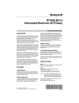
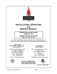
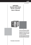
GeniSys 120V
™
PARTS & ACCESSORIES
Model 7505
Advanced Burner Control
Description / Applications
The Beckett GeniSysTM Advanced Burner Control is a
120 Vac primary safety control for residential and light
commercial oil burners used in boiler, furnace, and
water heater applications having firing rates less than
20 GPH. The GeniSys is used with a suitable cad cell
flame sensor to control the oil burner motor, igniter,
and optional solenoid valve. It has 24 Vac thermostat
terminals (if applicable) compatible with both mechanical
and many power stealing thermostats. It can also provide
interrupted or intermittent duty ignition.
Features
◦ Thermostat / Operating (if applicable) and Limit Control Compatible
◦ Welded Relay Protection
◦ Limited Recycle
◦ Limited Reset
◦ 3 Status Lights
◦ Valve-On Delay / Motor-Off Delay (Field programmable with Beckett add-on Display)
◦ 15 Second Lockout Time
◦ Interrupted or Intermittent Duty Ignition
◦ Technician Pump Priming Mode
◦ Disable Function
◦ Communication Ports (2)
Table 1 - Models and Cross Reference Guide
Beckett GeniSys
Control Part No.
Lockout
Time
Valve-on
delay time2
Motor-off
delay time2
Replaces
Honeywell:
Replaces
Carlin:
7505A 0000
15 sec
-
-
R7184A, R8184G
48245, 40200,
42230, 502001
7505B 1500
15 sec
15 sec
-
R7184B
-
7505P 1515
15 sec
15 sec
15 sec
7505P 1530
15 sec
15 sec
7505P 152M
15 sec
15 sec
R7184P, R7184U
1
602001
30 sec
R7184P, R7184U
1
602001
2 min
R7184P, R7184U1
602001
1 - Beckett snap-on alarm module required for direct replacement of this control.
2 - Valve-on delay and motor-off delay timings on all models are programmable with Beckett snap-on
programming display. Other factory set timings are available. Contact Beckett for alternate timings.
2
Figure 1 – Getting to know the control
Reset Button
with Red Light
Yellow Light
Green Light
Communication
Port 2
Thermostat
Terminals
(if applicable)
Communication
Port 1
Wiring
Connections
Cad Cell Connections
Optional Snap-on Display Module:
For programming and diagnostics
Optional Snap-on Alarm Module:
For adding isolated low voltage alarm
contacts to the base control. See Alarm
Module Instructions for specifications.
120v GeniSys Control Installation and Operation Manual
3
Do Not Use This
Control in an
Application that is
Not Within the Ratings Listed in This
Section. Improper Control Operation
May Result.
Electrical Ratings
Inputs:
◦ Voltage: 120 Vac nominal (102 to 132
Vac)
◦ Current: 100 mA nominal (150 mA max
at 132 Vac)
◦ Frequency: 60 Hz
Outputs:
◦ Motor: 120 Vac, 10 full load amps (FLA), 60
locked rotor amps (LRA)
*Note: Reduce motor FLA rating by
igniter current
◦ Igniter: 120 Vac, 3 A @ 0.7 PF min
◦ Solenoid Valve: 120 Vac, 1 A @ 0.7 PF
min
◦ Thermostat Anticipator Current: 0.1 A
(if applicable)
◦ Thermostat Voltage: 24 Vac (if
applicable)
Environmental Ratings:
◦ Storage and Operating Ambient
Temperature: -40°F to +150°F (-40°C to
+65°C)
◦ Moisture: 5 to 95% RH, non-condensing
and non-crystallizing
Approvals:
◦ Underwriters Laboratory Recognition
per UL372 and UL1998, and CSA
C22.2 No. 199
Do Not Use This
Control Above 19.9
GPH
Most codes and standards require additional
safeguards and features for oil burner inputs
above 19.9 gph. Consult the appliance
manufacturer’s instructions for control
selection.
4
Installation/Operation/
Maintenance
Professional
Service Required
Incorrect installation or misuse
of this control could result in
severe personal injury, death, or
substantial property damage from
heavy smoke, explosion or fire.
Please read and understand the manual supplied
with this control. This control must be installed,
adjusted and put into operation only by a qualified
individual or service agency that is:
• Licensed or certified to install and provide
technical service to oil heating systems.
• Experienced with all applicable codes,
standards and ordinances.
• Responsible for the correct installation and
commission of this equipment.
• Skilled in the adjustment of oil burners using
combustion test instruments.
The installation must strictly comply with all
applicable codes, authorities having jurisdiction
and the latest revision of the National Fire
Protection Association Standard for the
Installation of Oil-Burning Equipment, NFPA 31
(or CSA-B139 and CSA-B140 in Canada).
Regulation by these authorities take precedence
over the general instructions provided in this
installation manual.
Frozen Plumbing
and Water Damage
Hazard
If the residence is unattended in severely
cold weather, burner primary control safety
lockout, heating system component failures,
power outages or other electrical system
failures could result in frozen plumbing
and water damage in a matter of hours. For
protection, take preventive actions such
as having a security system installed that
operates during power outages, senses low
temperature and initiates an effective action.
Consult with your heating contractor or a
home security agency.
Fire or Explosion
Hazard
Can cause severe injury, death, or
property damage.
• The control can malfunction if it gets wet,
leading to accumulation of oil or explosive oil
vapors.
• Never install where water can flood, drip or
condense on the control.
• Never use a control that has been wet - replace it.
Electrical Shock
Hazard
Electrical shock can cause severe
personal injury or death.
• Disconnect ALL electrical power to the
appliance/burner circuit before installing or
servicing this control.
• Provide ground wiring to the appliance,
burner and metal control mounting box.
• Perform all wiring in compliance with the
National Electrical Code ANSI/NFPA 70
(Canada CSA C22.1).
Incorrect Wiring
Will Result in
Improper Control Operation
• GeniSys wiring label colors may not match
the wire colors of the burner or other
manufacturers’ controls.
• The GeniSys Control should be wired
according to the appliance manufacturer’s
instructions.
Mounting:
◦ Mount the control on a 4” x 4” junction
box on the burner, or inside the
appliance cabinet. In replacement
applications, mount the new control in
the same location as the old control. In
some replacement applications, it may
be necessary to rotate the control on
the 4” x 4” box for best fit.
◦ Mounting orientation: any orientation is
acceptable.
Wiring:
Explosion, Fire,
Scald, and Burn
Hazard
All heating appliances must have
HIGH LIMIT protection to interrupt
electrical power and shutdown the
burner if operating or safety controls fail and
cause a runaway condition.
• Follow the appliance manufacturer’s wiring
diagrams and note all required safety
controls.
• Typical safety controls include high
temperature or pressure limits, low water
cutoffs, pressure relief valves and blocked
flue sensing switches.
• Verify all limit and safety controls are installed
and functioning correctly, as specified by the
manufacturer, applicable safety standards,
codes and all authorities having jurisdiction.
• Ensure that the appliance is free of oil and oil
vapor before starting or resetting the burner.
◦ Make sure all appliance wiring complies
with all local codes and ordinances.
◦ Make connections to the control’s
terminals as shown in Figures 2 through
9. Refer to the label on the underside
of the control for wiring details.
Some Thermostats
Are Polarity
Sensitive. Reversed polarity could cause
erratic cycling of the burner control.
◦ Connect the wire from the RH or R
terminal on the thermostat to the TR
terminal on the control (if applicable).
◦ Connect the wire from the W terminal
on the thermostat to the TW terminal on
the control (if applicable).
120v GeniSys Control Installation and Operation Manual
5
Typical Boiler Wiring:
Figure 2 – 7505A (for replacement of R8184G)
Figure 4 – 7505B (for replacement of R7184B)
► Intermittent
ignition, no valve-on delay,
no motor-off delay
► Interrupted
ignition, valve-on delay only
(no motor-off delay)
BOILER CONTROL
BOILER CONTROL
70
T
W
T
R
80
50
80
50
60
B2
B1
L1
L1
T
W
L2
L2
T
R
B2
B1
IGNITER
70
70
50
70
THERMOSTAT
60
60
50
80
L1
L2
80
60
L1
L2
THERMOSTAT
IGNITER
IGNITER
IGNITER
L2 (IGN)
L2 (IGN)
MOTOR
L2 (MTR)
MOTOR
MOTOR
L2 (MTR)
MOTOR
L1LIMIT
LIMIT
L1LIMIT
LIMIT
TR-TW
JUMPER
L2
VALVE
TR
L2 (VLV)
TW
L2
OIL VALVE
VALVE
TR
L2 (VLV)
TW
TR-TW Terminals
CAD
CELL
CAD CELL
TR-TW TERMINALS
Located
on
LOCATED
ON OPPOSITE
opposite
side of
SIDE OF CONTROL
Control
CAD
CELL
CAD CELL
(If applicable)
Figure 3 – 7505A (for replacement of R7184A)
TR-TW
JUMPER
TR-TW Terminals
TR-TW TERMINALS
Located
on
LOCATED
ON side
OPPOSITE
opposite
of
SIDE OF CONTROL
Control
(If applicable)
Figure 5 – 7505P (for replacement of R7184P)
► Interrupted
ignition, no valve-on or
motor-off delay
► Interrupted
ignition, valve-on and motor-
off delays
BOILER CONTROL
L2
L2
T
50
W
T
R
50
80
L1
80
L1
60
B2
70
B1
L1
L1
T
W
L2
L2
T
R
B2
70
60
70
60
70
50
B1
50
80
60
80
BOILER CONTROL
THERMOSTAT
THERMOSTAT
IGNITER
IGNITER
IGNITER
IGNITER
L2 (IGN)
L2 (IGN)
MOTOR
L2 (MTR)
MOTOR
L2 (MTR)
MOTOR
L1LIMIT
LIMIT
L2
L1
LIMIT
L2
TR-TW
JUMPER
VALVE
TR
L2 (VLV)
TW
CAD
CELL
CAD CELL
MOTOR
OIL VALVE
TR
L2 (VLV)
TW
CAD
CELL
TR-TW Terminals
TR-TW TERMINALS
Located
on
LOCATED
ON side
OPPOSITE
opposite
of
SIDE OF CONTROL
Control
CAD CELL
TR-TW
JUMPER
VALVE
TR-TW Terminals
TR-TW TERMINALS
Located
on
LOCATED
ON side
OPPOSITE
opposite
of
SIDE OF CONTROL
Control
(If applicable)
(If applicable)
NOTE: To disable motor-off delay on a 7505P control,
jumper L1 and limit together and wire as shown in Fig. 4.
6
Typical Furnace Wiring:
Figure 6 – 7505A (for replacement of R8184G)
Figure 8 – 7505B (for replacement of R7184B)
ignition, no valve-on or
motor-off delays
70
80
SAFETY AND
OPERATING
LIMITS
80
60
60
70
60
70
W
L2
R
50
50
L1
W
SAFETY AND
OPERATING
LIMITS
ignition, valve-on delay only
(no motor-off delay)
80
60
50
L1
L2
► Interrupted
70
R
50
80
► Intermittent
THERMOSTAT
THERMOSTAT
IGNITER
IGNITER
IGNITER
IGNITER
L2 (IGN)
L2 (IGN)
MOTOR
L2 (MTR)
MOTOR
L2 (MTR)
MOTOR
L1LIMIT
LIMIT
VALVE
TR
L2 (VLV)
TW
CAD
CELL
CAD CELL
OIL VALVE
TR-TW Terminals
(If applicable)
70
70
(If applicable)
Figure 9 – 7505P (for replacement of R7184P)
► Interrupted
ignition, valve-on and motor-
off delays
80
L1
R
L2
80
W
60
70
R
50
THERMOSTAT
IGNITER
IGNITER
IGNITER
L2 (IGN)
L2 (IGN)
MOTOR
L2 (MTR)
MOTOR
L2 (MTR)
MOTOR
L1LIMIT
L2
70
W
IGNITER
LIMIT
60
50
SAFETY AND
OPERATING
LIMITS
THERMOSTAT
MOTOR
TR-TW
JUMPER
VALVE
TR
L2 (VLV)
TW
L1
LIMIT
L2
OIL VALVE
CAD CELL
TR-TW
JUMPER
VALVE
TR
L2 (VLV)
TW
TR-TW Terminals
CAD
CELL
TR-TW Terminals
TR-TW TERMINALS
Located
on
LOCATED
ONside
OPPOSITE
opposite
of
SIDE OF CONTROL
Control
80
60
60
50
50
TR
TW
CAD CELL
ignition, no valve-on or
motor-off delay
SAFETY AND
OPERATING
LIMITS
VALVE
L2 (VLV)
CAD
CELL
TR-TW TERMINALS
Located
on
LOCATED
ONside
OPPOSITE
opposite
of
SIDE OF CONTROL
Control
► Interrupted
L1
TR-TW
JUMPER
L2
Figure 7 – 7505A (for replacement of R7184A)
L2
L1LIMIT
LIMIT
TR-TW
JUMPER
L2
80
MOTOR
TR-TW Terminals
TR-TW TERMINALS
Located
on
LOCATED
ON OPPOSITE
opposite
side of
SIDE OF CONTROL
Control
CAD
CELL
CAD CELL
(If applicable)
TR-TW TERMINALS
Located
on
LOCATED
ON side
OPPOSITE
opposite
of
SIDE OF CONTROL
Control
(If applicable)
NOTE: Motor-off delay on a 7505P will be disabled if the
safety and operating limits as shown in Figures 5 and 9
interrupt power to the control terminal L1.
Connect thermostat leads (if applicable) to the TR and
TW terminals on the control or jumper the TR and TW
terminals on the control as directed by the appliance
wiring diagram.
NOTE: If the thermostat short cycles or operates improperly, it may require an isolation relay for proper operation.
The Beckett A/C Ready Kit (part no. 51950U) provides
this function. Wiring instructions are included with the
A/C Ready Kit.
120v GeniSys Control Installation and Operation Manual
7
Startup / Checkout
Fire Hazard
Reset and Service by Qualified
Technician only.
If the burner or control fails any of the
following tests, recheck control wiring. If
the burner or control still fails any tests,
replace the control.
Starting the System
1. Open the shut-off valves in the
supply line from the oil tank.
2. Close the disconnect switch to
supply power to the burner.
3. Adjust the thermostat or boiler
control to call for heat.
- If the pump has not been primed,
refer to “Priming the Pump” in the
“Operation” section of this manual.
4. Monitor burner operation to ensure
that the burner ignites.
5. End the call for heat. Verify that the
burner turns off before leaving the
installation site.
green light is on continuously and
that the control remains in Standby
mode.
4. End the call for heat and remove the
cad cell jumper.
◦ Simulate Flame Failure and Ignition
Failure
1. Refer to the steps for “Starting the
System” and have the system call
for heat.
2. After flame is established and the
burner igniter turns off, close the
hand valve in the oil supply line.
3. At flame loss, the control will enter
Recycle mode. Verify that the green
light is flashing. The control will
remain in Recycle for 60 seconds.
4. After the 60 second recycle period,
the control will try to restart the
system.
5. After the 15 second lockout time, the
control will lock out the burner and
the reset button will flash. Verify that
the burner motor and igniter are off
and that the burner oil solenoid valve
(if used) is not energized.
6. Open the hand valve in the oil line.
Check Safety Features
◦ Safe Start Check
1. Place a jumper across the cad cell
terminals.
2. Refer to the steps for “Starting the
System” and have the system call
for heat.
3. Burner must not start. Verify that the
8
7. Click the reset button and verify that
the red light in the reset button shuts
off and that the burner lights.
8. End the call for heat.
◦ Before leaving the installation, verify
that all thermostat and boiler/furnace
control wiring is correct. Consult
heating appliance manual for directions.
Sequence of Operation
Burner States
1. Standby: The burner is idle,
waiting for a call for heat.
Standby
2
2. Valve-On Delay: The igniter and
motor are on while the control
delays turning on the oil solenoid
valve for the programmed time.
3. Trial For Ignition: The oil solenoid
valve is energized. A flame should
be established within the factory
set trial for ignition time (“lockout
time”).
Valve-on
delay
8
Motor-off
delay
Trial for
ignition
Pump
prime
4
Lockout
Ignition
carryover
6
7
Run
Recycle
is then sent to Motor-Off Delay, if
applicable, or it is shut down and
sent to Standby.
7. Recycle: If the flame is lost while
the burner is firing, the control shuts
down the burner, enters a 60 second
recycle delay, and repeats the
ignition sequence. The control will
continue to Recycle each time the
flame is lost, until it reaches a preset time allotment. The control will
then go into Hard Lockout instead
of recycle. This feature prevents
excessive accumulation of oil in the
appliance firing chamber.
a. The trial for ignition (lockout)
time expired without flame being
established.
b. The cad cell detected flame at the
end of the Valve On Delay state.
c. Flame is lost while the burner
is firing and the pre-set time
allotment is expired. See
“Recycle” (Item 7).
To reset the control from lockout
click the button 1-second.
8. Motor-Off Delay: If applicable, the
oil solenoid valve is turned off and
the control delays turning the motor
off for the set motor-off delay time
before the control returns to standby.
NOTE: A recurrence of the above
failure modes or a failed welded
relay check could cause the control
to enter a Hard Lockout state that
must be reset only by a qualified
service technician.
9. Pump Prime: The igniter and motor
are on with the oil solenoid valve
energized for 4 minutes. During
Pump Prime mode, the cad cell is
disregarded, allowing the technician
to prime the pump without having to
jumper the cad cell.
To reset from Hard Lockout, hold the
reset button for 15 seconds until the
yellow light turns on.
6. Run: The flame is sustained until the
call for heat is satisfied. The burner
3
5
4. Lockout: The control has shut
down for one of the following safety
reasons:
5. Ignition Carryover: Once flame is
established, the igniter remains on
for 10 additional seconds to ensure
flame stability.
9
1
Reset Button Operation
Table 2 explains what action the control
will take when the reset button is pressed
for different lengths of time during the
various burner operating states.
120v GeniSys Control Installation and Operation Manual
9
2. Initiate a call for heat.
Priming the Pump
3. After the burner starts, press and
hold the reset button for 15 seconds
until the yellow light turns on. This
indicates that the button has been
held long enough.
1. Prepare the burner for priming
by attaching a clear plastic hose
over the bleed port fitting and fully
opening the pump bleed port. Use a
suitable container to collect purged oil.
4. Release the reset button. The yellow
light will turn off and the burner will
start up again.
Hot Gas Puff-Back
and Heavy Smoke
Hazard
Failure to bleed the pump properly could
result in unstable combustion, hot gas puffback and heavy smoke.
• Do not allow oil to spray into a hot
combustion chamber while bleeding air from
the pump.
• Install a gauge in the nozzle discharge port
tubing or fully open the pump bleed valve to
prevent oil spray from accumulating in the
combustion chamber during the air bleed
procedure.
• Ensure that all bubbles and froth are purged
from the oil supply system before tightening
the pump bleed valve.
• Ensure that the appliance is free of oil and oil
5. At burner start up, click the reset
button while the igniter is still on.
This will transition the control to a
dedicated Pump Prime mode, during
which the motor, igniter, and valve
are powered for four minutes. The
yellow light will be on.
6. Bleed the pump until all froth and
bubbles are purged. If desired,
terminate the call for heat or hold the
reset button for at least one second
to exit Pump Prime mode and return
to Standby.
7. At the end of 4 minutes, the yellow
light will turn off and the control will
Table 2 - Reset Button Operation
Pushing the reset button will:
If the burner is in the
below state:
Button Click
(press < 1 second)
Lockout
Button Hold
(press > 1 second)
Button Hold
(press 15+ seconds)
Reset from Restricted
(Hard) Lockout
Reset from Soft Lockout
Valve-on Delay, Trial for
Ignition, Ignition Carryover
Motor-Off Delay,
Standby
Go to Pump Prime (see
Disable the Burner:
“Priming the Pump” above) Any time the burner is
running, press and hold
No action
the reset button to disable
the burner. The burner will
No action
remain off as long as the
button is held.
Pump Prime
No action
Run (igniter is shut off)
Enables Pump Priming:
After the reset button has
been held for 15 seconds,
the button can then be
clicked during the next
ignition sequence to enter
Pump Prime mode.
Exit Pump Prime mode and return to Standby
Table 3 - Status Lights
Light Color
On Continuously
Flashing
Red
Restricted (Hard) Lockout
Soft Lockout
Green
Flame Sensed during normal operation (Could be stray
light during standby)
Recycle
Yellow
Control is in Pump Prime mode or
Reset button currently held for 15+ seconds.
N/A
10
automatically return to standby mode.
8. If prime is not established during the
four minute pump prime mode, return
to step 5 to re-enter Pump Prime
mode. Repeat steps 5 through 7
until the pump is fully primed and the
oil is free of bubbles.
9. Terminate the call for heat, and the
control will resume normal operation.
to limit accumulation of unburned oil in
the combustion chamber.
◦ To reset, hold the button down for 15
seconds until the red light turns off and
the yellow light turns on.
◦ Always verify the control functions
according to all specifications before
leaving the installation site.
◦ Replace the control if it does not
operate as specified.
Cad Cell Resistance Measurement
Disable Function
If the Beckett 7505 control is equipped
with the GeniSys Display Module, part
52067U, the cad cell resistance can be
selected and read on the LCD screen.
Also, the GeniSys Contractor Tool, part
52082U, can be used for this purpose.
◦ Any time the burner is running, press
If these are not available, the cad cell
leads can be unplugged from the control
and the resistance measured with a
meter in the conventional way.
Conduct these tests with flame present.
Flame Detection Range
Normal (0 - 1600 ohms)
Limited (1600 ohms to lockout)
and hold the reset button to disable the
burner. The burner will remain off as
long as the button is held.
Maintenance
Oil heating systems require annual
service performed by a qualified,
professional service agency. The 7505
primary control should be inspected
during this service routine according to
the following checklist:
□ NOTE: The 7505 control has no
Resetting From Restricted or
Hard Lockout
Fire & Smoke
Hazard
Before starting or resetting the
control from restricted lockout
state, troubleshoot the heating
system for the root cause(s) of
the lockout.
• Make necessary repairs or adjustment to
ensure a safe start condition.
• Ensure that the appliance is free of oil and oil
vapors before starting or resetting the burner.
□
□
□
□
□
◦ If the control continues to lock out
without a satisfied call for heat, or
fails the motor relay check, the control
enters Hard (restricted) Lockout in order
□
120v GeniSys Control Installation and Operation Manual
serviceable internal parts. Do not
attempt to remove cover.
Inspect the exterior of the control.
Replace the control if there is any
sign of impact damage, water or
corrosion.
Use a multimeter to test the line
voltage at control L1 and L2. It
should be 102 - 132 Vac.
Inspect all external wiring for secure
connections and verify insulation
integrity.
Verify the control lockout and
operation sequence, (Reference
Startup/Checkout section).
Observe a full operating cycle to
prove the sequence and timings are
correct.
Replace any control that does not
meet listed specifications with an
equivalent replacement unit.
11
Limited Warranty Information
The R. W. BECKETT CORPORATION (“Beckett”) warrants to persons who
purchase its “Products” from Beckett for resale, or for incorporation into a
product for resale (“Customers”), that its equipment is free from defects in
material and workmanship. To qualify for warranty benefits, products must be
installed by a qualified service agency in full compliance with all codes and
authorities having jurisdiction, and used within the tolerances of Beckett’s
defined product specifications.
To review the complete warranty policy and duration of coverage for a specific
product, or obtain a written copy of warranty form 61545, please choose one of
the following options:
1. Visit our website at: www.beckettcorp.com/warranty
2. Email your request to: [email protected]
3. Write to: R. W. Beckett Corporation, P. O. Box 1289, Elyria, OH 44036
NOTE: Beckett is not responsible for any labor cost for removal and
replacement of equipment.
THIS WARRANTY IS LIMITED TO THE PRECISE TERMS SET FORTH
ABOVE, AND PROVIDES EXCLUSIVE REMEDIES EXPRESSLY IN LIEU
OF ALL OTHER REMEDIES, AND IN PARTICULAR THERE SHALL BE
EXCLUDED THE IMPLIED WARRANTIES OF MERCHANTABILITY AND
FITNESS FOR A PARTICULAR PURPOSE. IN NO EVENT WILL BECKETT
BE LIABLE FOR ANY INCIDENTAL OR CONSEQUENTIAL DAMAGE OF ANY
NATURE. Beckett neither assumes, nor authorizes any person to assume
for Beckett, any other liability or obligation in connection with the sale of this
equipment. Beckett’s liability and Customer’s exclusive remedy is limited to the
cost of the product.
CORPORATION
USA: P.O. Box 1289 ● Elyria, OH 44036
Canada: R.W. Beckett Canada, Ltd. ● Unit #3, 430 Laird Road ● Guelph, Ontario N1G 3X7
www.beckettcorp.com
Form No. 61649 R14, Printed in USA 10/10