1
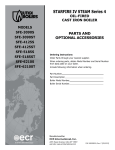
STARFIRE IV STEAM Series 4
MODELS
SFE-3090S
SFE-3090ST
SFE-4125S
SFE-4125ST
SFE-5185S
SFE-5185ST
SFE-6210S
SFE-6210ST
OIL-FIRED
CAST IRON BOILER
INSTALLATION, OPERATION &
MAINTENANCE MANUAL
PATENT 7,823,544
Manufactured by:
ECR International, Inc.
2201 Dwyer Avenue, Utica NY 13501
web site: www.ecrinternational.com
An ISO 9001-2008 Certified Company
P/N 240009806, Rev. B [03/2014]
DIMENSIONS
Figure #1
DIMENSIONS
Boiler No.
SFE-3090
SFE-4125
SFE-5185
SFE-6210
Front of Jacket
Length of Flush
to Center Line of Flue Outlet Diameter
Jacket
Flue Outlet
-A-B-C-
16⅜"
20¼"
23⅝"
27½"
6½"
8½"
10¼"
85/₁₆"
6"
6"
7"
8"
STANDARD EQUIPMENT: Crated boiler, flush jacket, oil burner,
target wall/liner, safety valve, steam water level gauge, steam
pressure gauge, steam pressure control, low water cut-off, drain
valve, wiring harness, burner electric disconnect, plastic cover, 2"
supply tapping, 1½" return tapping, skim port, and primary control.
(NOTE: For tankless heater units, add tankless hot water coil, and
low limit control.)
2
RATINGS, DATA
RATINGS
Boiler Model
Number
Oil Burner Input(1)
WITHOUT
TANKLESS
WITH TANKLESS
G.P.H.
MBH(2)
Heating
Capacity
MBH(4)
SFE-3090S
SFE-3090ST
0.90
126
SFE-4125S
SFE-4125ST
1.25
SFE-5185S
SFE-5185ST
SFE-6210S
SFE-6210ST
Net AHRI Ratings(3)
Min. Natural Draft
Chimney Size
A.F.U.E.
Rating(4)
Steam
MBH
Sq. Ft.
Steam
Round
Square
106
80
333
6
8"x8"x15'
82.0
175
147
110
458
6
8"x8"x15'
82.0
1.85
259
216
162
675
8
8"x8"x15'
82.0
2.10
294
247
185
771
8
8"x8"x15'
82.0
NOTES:
(1)
Burner input is based on an oil heating value of 140,000 Btu/gal.
(2)
MBH = 1000 Btu per hour [Btu =British Thermal Unit].
(3)
Net AHRI Steam Ratings based on piping and pick-up allowance of 1.333. Consult manufacturer before selecting boiler for
installations having unusual piping and pick-up requirements, such as intermittent system operation, extensive piping, etc.
(4)
Heating Capacity and AFUE based on 13.0% CO2 with 0.02" W.C. draft over fire and #1 smoke or less. Tested in accordance with
U.S. Department of Energy test procedures.
TANKLESS WATER HEATER CAPACITIES
Boiler Model
Number
Boiler Water
Tankless
Content
Input Tankless
Heater Capacity
(Gallons)
Rate Heater
Intermittent Draw
To
G.P.H. Number
To Water
G.P.M.
LWCO
Line
Line
SFE-3090ST
0.90
L-24
2
11
8
SFE-4125ST
1.25
L-24
4½
13
9
SFE-5185ST
1.85
L-24
4½
15
10
SFE-6210ST
2.10
L-24
4½
17
11
3
TABLE OF CONTENTS
IMPORTANT: Read and understand the following
instructions COMPLETELY before installing.
Dimensions.........................................................2
Ratings, Data......................................................3
! WARNING
Safety Symbols...................................................4
Locating The Boiler..............................................5
Installations of boilers and venting shall be done
only by qualified expert and in accordance with this
manual. Installing or venting a boiler or any other
gas appliance with improper methods or materials
could result in serious injury or death due to fire
or to asphyxiation from poisonous gases such as
carbon monoxide which is odorless and invisible.
Ventilation And Combustion Air.............................6
Supply And Return Piping.....................................8
Venting System Inspection & Installation..............12
Oil Tank And Piping............................................13
Electrical Wiring................................................14
! WARNING
Operating Instructions........................................16
Maintenance Procedures.....................................19
Keep boiler area clear and free from combustible
materials, gasoline and other flammable vapors and
liquids.
Service Checklist...............................................21
Do not obstruct air openings to boiler room.
Modification, substitution or elimination of factory
equipped, supplied or specified components could
result in personal injury or the loss of life.
KEEP THIS MANUAL NEAR BOILER
RETAIN FOR FUTURE REFERENCE
SAFETY SYMBOLS
Owner - Installation and service of this boiler must
be performed by a qualified installer.
The following defined symbols are used throughout this
manual to notify reader of potential hazards of varying risk
levels.
!
Installer - Leave all instructions with the boiler for
future reference.
DANGER
When this product is installed in the Commonwealth
of Massachusetts the installation must be performed
by a Licensed Plumber or Licensed Gas Fitter.
Indicates a hazardous situation which, if not
avoided, WILL result in death or serious injury.
! WARNING
Indicates a hazardous situation which, if not avoided,
could result in death or serious injury.
! CAUTION
Indicates a hazardous situation which, if not
avoided, could result in minor or moderate injury.
NOTICE
PATENT 7,823,544
Indicates information which should be followed to
ensure proper installation and operation.
4
LOCATING THE BOILER
! WARNING
•Installations shall conform to the requirements of
the authority having jurisdiction. Such applicable
requirements take precedence over the general
instructions of this manual.
Fire hazard. Do not install boiler on combustible
flooring or carpeting. Failure to follow these
instructions could result in death or serious injury.
•Where required by the authority having jurisdiction,
the installation must conform to the American Society
of Mechanical Engineers Safety Code for Controls and
Safety Devices for Automatically Fired Boilers, ANSI/
ASME No. CSD-1.
FOR INSTALLATION ON NON-COMBUSTIBLE FLOORS ONLY
Boiler must not be installed on carpeting or vinyl flooring.
Minimum clearances to combustible construction are:
•Locate boiler in front of final position before removing
crate.
•Provide level solid base as near chimney as possible
and centrally located with respect to heat distribution
system as practical.
•Allow 24 inches in front, top and right hand side for
servicing and cleaning, or removing tankless water
heating coil.
TOP
24 IN.
FRONT
24 IN.
FLUE CONNECTOR
9 IN.
REAR
24 IN.
LEFT SIDE
6 IN.
RIGHT SIDE
24IN.
NOTE: Clearance for access should exceed fire protection
clearance.
•Recommend 24 inches be allowed in back of boiler for
convenience when skimming hole is used.
•When installed in a utility room, the door should be
wide enough to allow largest boiler part to enter, or to
permit replacement of another appliance such as water
heater.
Figure #2 - Minimum Clearances To Combustible
Construction (as seen from above)
•Install boiler such that oil ignition system components
are protected from water (dripping, spraying, rain etc.)
during appliance operation and service.
BACK
24"
6"
BOILER
24"
FRONT
5
24"
VENTILATION AND COMBUSTION AIR
! WARNING
Asphyxiation, fire hazard. Do not obstruct air
openings to combustion area. Follow instructions
below, to maintain adequate combustion air.
COMBUSTION AIR REQUIREMENTS
(Minimum Opening Requirement)
Unconfined Area*
Confined Area**
Outside
Inside
Outside Combustion Air
Combustion Air
Input (Mbh)
Vertical Ducts
Horizontal Ducts
Combustion Air
1 Sq. In./1000 BTU/ 1 Sq. In./4000 BTU/Hr 1 Sq. In./2000 BTU/Hr
1 Sq.In./5000 BTU/Hr Hr
(Min. 100 Sq. In.)
(Step 4)
(Figures # 2 & #3)
(Figure # 4)
(Figure #1)
126
26
126
32
63
175
35
175
44
88
259
52
259
65
130
294
59
294
74
147
* A space whose volume is not less than 50 cubic feet per 1000 BTU/Hour of all appliances installed in that space (cubic feet of
space = height x width x length)
** A space whose volume is less than 50 cubic feet per 1000 BTU/Hour of all appliances installed in that space (cubic feet of space
= height x width x length)
1. Ventilation of boiler room must be adequate enough to
4. When air for combustion and room ventilation is from
provide sufficient air to properly support combustion,
venting and maintain safe ambient temperatures under
normal operating conditions.
2. When the boiler is located in an unconfined space in a
building of conventional construction frame, masonry
or metal, infiltration normally is adequate to provide
air for combustion and ventilation. However, in any
building which has been altered to conserve energy
or to minimize infiltration, the boiler area should
be considered as a confined space. If there is any
doubt, install air supply provisions for combustion
and ventilation in accordance with Chapter 5, Air for
Combustion and Ventilation, of NFPA 31, Standard
for the Installation of Oil Burning Equipment. The
recommendations that follow, or applicable provisions
of the local building codes.
3. When the boiler is installed in an unconfined space,
in a building of unusually tight construction, air for
combustion and room ventilation must be obtained
from outdoors or from spaces freely communicating
with the outdoors. A permanent opening or openings
having a total free area of not less than 1 square inch
per 5,000 BTU per hour of total input rating of all
appliances shall be provided. Ducts may be used to
convey make-up air from the outdoors and shall have
the same cross-sectional area of the openings to which
they are connected.
inside buildings, the confined space shall be provided
with two permanent openings, one starting 12 inches
from the top and one 12 inches from the bottom of the
enclosed space. Each opening shall have a minimum
free area of 1 square inch per 1,000 BTU per hour of
the total input rating of all appliances in the enclosed
space, but must not be less than 100 square inches.
These openings must freely communicate with the
interior areas having adequate infiltration from the
outside. See Figure #3.
Figure #3
CHIMNEY
OR
L TYPE VENT PIPE
BASEBOARD
VENT PIPE
12"
VENTS
12"
6
VENTILATION AND COMBUSTION AIR
5. When the boiler is installed in a confined space and
Figure #4
all air is provided from the outdoors, the confined
space shall be provided with two permanent openings,
one commencing within 12 inches from the top and
one commencing 12 inches from the bottom of the
enclosure. The openings shall communicate directly, or
by ducts, with the outdoors or spaces (crawl or attic)
that freely communicate with the outdoors. One of the
following methods must be used to provide adequate
air for ventilation and combustion.
A. When directly communicating with the outdoors,
each opening shall have a minimum free area of 1
square inch per 4,000 BTU per hour of total input
rating of all equipment in the enclosure. (Figure
#4)
B. When communicating with the outdoors by means
of vertical ducts, each opening shall have a
minimum free area 1 square inch per 4,000 BTU
per hour of total input rating of all appliances in the
enclosed space. (Figure #5)
C. If horizontal ducts are used, each opening shall
have a minimum free area 1 square inch per 2,000
BTU per hour total input rating of all appliances in
the enclosed space. (Figure #6)
D. When ducts are used, they shall be of the same
cross sectional area as the free area of the area of
the openings to which they connect. The minimum
dimension of rectangular air ducts shall not be less
than 3 inches.
Figure #5
6. In calculating free area using louvers, grills or screens
for the above, consideration shall be given to their
blocking effect. Screens used shall not be smaller than
1/4 inch mesh. If the free area through a design of
louver or grill is known, it should be used in calculating
the size opening required to provide the free area
specified. If the design and free area is not known, it
may be assumed that wood louvers will have 20-25%
free area and metal louvers and grills will have 60-75%
free area. Louvers and grills shall be fixed in the open
position or interlocked with the boiler so that they are
opened automatically during boiler operation.
Figure #6
7
SUPPLY AND RETURN PIPING
! WARNING
Burn or Scald Hazard. Discharge line shall be installed to safety valve outlet connection to avoid burns,
scalding, or water damage due to discharge of steam and/or hot water during operation.
Discharge line shall:
•Connect to safety valve outlet. Piped down to safe point of disposal. Check local codes for maximum
distance from floor or allowable safe point of discharge.
•Pipe size be of equal to or greater than of safety valve outlet over entire length of discharge line.
•Have no intervening shutoff valve between safety valve and discharge to atmosphere. Do not plug or
place any obstruction in discharge line.
•Terminate freely to atmosphere where any discharge will be clearly visible and at no risk of freezing.
•Allow complete drainage of valve and discharge line.
•
Install safety valve with spindle in vertical position.
•
Do not install shutoff valve between boiler and safety valve.
•
Support safety valve discharge piping.
•Be short and straight as possible.
•Terminate with plain end, not threaded.
•Constructed of material suitable for exposure to temperatures of 375° F (191°C); or greater.
Refer to local codes and appropriate ASME Boiler and Pressure Vessel Code for additional installation
requirements.
Figure 4 - Safety Valve
SAFETY VALVE
DISCHARGE
PIPING
Check local codes
for maximum
distance from
floor or other
allowable safe
point of discharge
6" Above Floor
8
SUPPLY AND RETURN PIPING
1. Suggested piping for steam heating system can be
seen in Figure #7. Actual piping may vary based on
system design and local conditions.
Figure #7
9
SUPPLY AND RETURN PIPING
!
2. See Figure #8 for typical piping for domestic hot water
heater.
•Automatic mixing valve must be installed on tankless
heater outlet. Install per valve manufacturer's
instructions.
DANGER
Water temperatures exceeding 125°F will cause
severe burns instantly or death by scalding.
•Install adjustable flow restrictor in cold water inlet
due to varying water conditions.
3. See Figures #9 and #10 for the suggested piping for
a modular steam boiler.
Figure #8
PIPING FOR BUILT-IN
DOMESTIC
HOTBUILT-IN
WATER HEATER
PIPING FOR
DOMESTIC HOT WATER HEATER
UNTEMPERED HOT WATER TO
AUTOMATIC WASHER
UNTEMPERED
HOT WATER
TEMPERING VALVE
INSTALLED BELOW CENTER
LINE OF BOILER HOT
CONNECTION
DOMESTIC
HOT WATER
FLOW
CONTROL
REGULATOR
T & P VALVE
COLD WATER
COLD WATER IN
10
SUPPLY AND RETURN PIPING
PUMPED RETURN
Figure #9
SUGGESTED PIPING FOR MODULAR STEAM BOILERS - PUMPED RETURN
STOP
VALVE
ST
EA
MM
AIN
F & T TRAP HIGH
LEVEL "SPILL"
(DO NOT USE WITH
CONDENSATE PUMP)
TO
SYSTEM
TRAP
CHECK
VALVE
FROM
RECEIVER
TANK
TO
RECEIVER
TANK
TO
RECEIVER
TANK
BLOWOFF
VALVE
STOP
VALVE
SOLENOID
VALVE
(OPTIONAL)
FROM
RECEIVER
TANK
Figure #10
RETURN
SUGGESTED PIPING FORGRAVITY
MODULAR
STEAM BOILERS - GRAVITY RETURN
STOP
VALVE
ST
EA
MM
AIN
TOM
E
ST
Y
S
2"
CHECK
VALVE
(OPTIONAL)
STOP
VALVE
28"
BLOWOFF
VALVE
RE
TU
11
RN
WATER
LINE
VENTING SYSTEM INSPECTION & INSTALLATION
! WARNING
If oil fired water heater is vented into same flue as boiler,
provide separate hole into chimney whenever possible.
Boiler is to be vented by natural draft and shall not
be connected into any portion of mechanical draft
operating system under positive pressure.
When this isn’t possible, use “Y” connection in flue pipe,
using separate draft regulator for each unit.
When chimney does not provide adequate draft to handle
input from water heater and boiler simultaneously, wire
units so only one will operate at a time, favoring water
heater.
•Inspect chimney to make certain it is constructed
according to the latest revision of the NFPA 211. Local
regulations may differ from this code and should be
checked. Where there is a conflict, the local code will
prevail.
•Install boiler into chimney having a masonry or metallic
chimney liner.
•Unlined chimney will have leaks that will cause poor
chimney performance (no draft), and could result in
positive pressure in the combustion chamber.
Figure #11
•Horizontal portions of venting system should not
exceed 10 feet in length. Horizontal lengths over 10 ft.
will have a negative effect on chimney performance.
MORE THAN 10’ (3.1 M)
10’ (3.1 M)
•Extend chimney at least 2 ft. above any portion of
building within 10 ft. Producing a -.02 inch W.C. draft
in the combustion chamber. See Figure #11.
HEIGHT ABOVE ANY
ROOF SURFACE WITHIN
10’ (3.1 M)
HORIZONTALLY
•See Ratings Table page 3 for recommended minimum
chimney or vent sizes.
RIDGE
•Inadequate draft causes improper combustion,
resulting in dirty flue ways and high fuel bills.
•Connect flue pipe same size as boiler outlet to chimney,
sloping upward continuously toward the chimney
approximately ¼" per foot. Bolt or screw joints
together to avoid sag.
12
2’ (.61 M) MIN.
CHIMNEY 3’ (.92 M)
GAS VENT OR
TYPE L VENT
2’ (.61 M) MIN.
OIL TANK AND PIPING
Tank Installation
•Install oil tank and piping in accordance with National
Board of Fire Underwriters and local regulations.
Fuel Pump Connections
•Fuel pump connections and by-pass should be made
according to instructions attached to fuel pump.
•Oil storage tank, vent, fill pipe and caps should be as
prescribed by local codes.
•If tank is more than 20' from boiler, install two stage
fuel unit in place of single stage pump supplied as
standard equipment with burner.
•In no case should vent pipe be smaller than 1¼" I.P.S.
Fill pipe should not be less than 2" I.P.S.
•Verify rotation and speed are the same and pump is
suitable for burner horsepower rating.
Suction Line Installation
•Suction line from tank to burner should be one
continuous piece of tubing to prevent air entering line.
Install oil line filter and shut-off valve in the suction line.
Install shut-off valves in both suction and return lines at
the burner for convenience in servicing burner.
Allow extra tubing at burner so burner may be removed
from boiler for cleaning without disconnecting tubing. An
optional flexible oil line is available. See Figures #12 #13.
•Suction line, must be ⅜" O.D. copper tubing for runs of
50 feet or less, and ½" O.D. for longer runs.
Oil Line Installation
•Oil return line, same size as suction line, must be used
on any installation where bottom of tank is below fuel
unit of burner.
•Bury oil lines or protect from mechanical injury.
•Flare fittings on all oil lines are recommended.
Compression fittings on suction line often allow air to
be drawn into fuel pump, making it difficult to maintain
oil pressure at nozzle.
•Do not run overhead fuel lines from tank to oil burner.
Figure #12 Typical Installation Single Pipe Oil
System
Figure #13 Typical Installation Two Pipe Oil System
13
ELECTRICAL WIRING
! WARNING
Thermostat Installation
1. Thermostat should be installed on inside wall about
four feet above floor.
2. NEVER install thermostat on outside wall.
3. Do not install thermostat where it will be affected by
drafts, hot or cold pipes, sunlight, lighting fixtures,
television, fireplaces, or chimneys.
4. Check thermostat operation by raising and lowering
thermostat as required to start and stop burner.
5. Instructions for final adjustment of thermostat
are packaged with thermostat (adjusting heating
anticipator, calibration, etc.).
Electrical shock hazard. Turn OFF electrical power
supply at service panel before making electrical
connections. Failure to do so could result in death
or serious injury.
Electrical wiring must conform with the latest revisions of
the National Electrical Code, ANSI/NFPA No. 70, and/or
local authority having jurisdiction.
1. When an external electrical source is utilized, the
boiler, when installed, MUST BE electrically grounded
in accordance with these requirements.
2. Install a fused disconnect switch between boiler and
meter at a convenient location.
3. When the boiler is equipped with self-energized
controls, no outside source of electric power shall be
connected to the circuit of this system. (See "Steam
Wiring" on next page.)
14
ELECTRICAL WIRING
STEAM WIRING W/BECKETT BURNER
TH-1
Thermostat (Millivolt)
TH-2
Thermostat (24 Volt)
TH-3
Thermostat (Line Voltage)
TR-1 Transformer (120V/24V/40VA)
TR-2 Transformer (120V/24V/50VA)
LGV24
Volt Gas Valve
PS
Pressure Switch
COMPONENT CODING
MR-PS Manual Reset Pressure Switch
Control Terminal
1K
Relay Coil
1K1
Relay Contacts
1K2
Relay Contacts
LS
Limit Switch
MS
Manual Switch
WIRING CODE
Line Voltage By Factory
Low Voltage By Factory
Line Voltage By Installer
Low Voltage By Installer
CIR
ECO
PSC
LWCO
EWF
PG
Circulator
Energy Cut-Off
Pilot Safety Coil
Wire Connection
Low Water Cut Off
Electric Water Feeder
Power Generator
NOTE: Not all components listed are used in all control systems.
15
OPERATING INSTRUCTIONS
Sequence Of Operation
On call for heat, thermostat will actuate, completing the
circuit to the boiler. In turn, the ignition systems are
activated and ignition will begin.
Figure #14
ELECTRONIC LOW
WATER CUT OFF
PRESSURE RELIEF
VALVE
In event of a low water condition, an automatic low water
cut-off device will interrupt power between the low water
cut-off and burner. Burner remains off until low water
condition is corrected, (i.e., manually restore boiler water
or utilize water feeder device which automatically restores
water to its normal operating level).
Installer - Before putting boiler in operation, test
mechanical low water cut-off device for proper operation.
While burner is on, open blow-off valve located in lower
portion of cut-off body. This will drain water quickly from
cut-off body and break circuit to burner. If it does not,
replace control.
!
TOP JACKET
PANEL
WATER
LINE
1/4" SLOT
INSPECTION
COVER
HOT
28"
BURNER
ELECTRICAL
DISCONNECT
MOUNTING
SCREWS
(BOTH SIDES)
DANGER
LOWER FRONT
JACKET PANEL
Water temperatures exceeding 125°F will cause
severe burns instantly or death by scalding.
Refill boiler to its normal water line.
Operating Instructions
•Start of heating season have venting system inspected.
Check vent pipe from boiler to chimney for signs
of deterioration by rust or sagging joints. Repair if
necessary.
•Remove vent pipe at base of chimney or flue and, using
mirror, check for obstruction and verify compliance to
latest revision of the NFPA 211.
•Operate lever of safety valve on boiler periodically to
verify it is functioning properly. See Figure #14.
•Safety relief valve should open before steam pressure
exceeds 15 psi. reading on the gauge. If this pressure
is exceeded and safety relief valve leaks steam when
boiler is operating at normal pressures, immediately
replace. Corrosion can build up rapidly at valve seat
and prevent its functioning as a safety device.
16
OPERATING INSTRUCTIONS
2. Check electrode setting, they may have been jarred out
Start-Up And Adjustment Of Oil Burner
(See oil burner instructions for nozzle and electrode setting)
3.
4.
Do not set fire visually.
Instruments are only reliable method to determine proper
air adjustments.
Improperly adjusted burner causes soot and high fuel bills
because of incomplete combustion of the fuel oil. This may
then require excessive boiler maintenance, service costs,
and in some instances, house cleaning or redecorating.
Consult a qualified service mechanic to make proper
adjustments with smoke tester, CO2 indicator, and draft
gauge. Bacharach or Dwyer test kits include these
instruments.
1. Check oil burner nozzle to verify it is tight in adapter.
Burner mounting bolts should be tight.
5.
6.
7.
8.
9.
of position during transportation.
Lubricate burner motor if necessary.
Set room thermostat to call for heat, or jump
thermostat contacts on boiler control.
Open all oil line valves.
Turn service switch on. Burner should start.
On one pipe fuel systems only, bleed pump as soon as
burner starts. Allow oil to run until all traces of air in
suction line disappear.
Turn “OFF” burner and install pressure gauge port on
pump.
Start burner again and check oil pressure for 140 lbs.
Adjust if necessary.
BECKETT AFG SETTINGS
BOILER
NO.
HEAD
TYPE
HEAD
SETTING
STATIC
PLATE
NOZZLE
PUMP
PRESSURE
[PSI]
AIR
BAND
AIR
SHUTTER
SFE-3090
L1
--
3⅜
0.75-60°B
150
1
3
SFE-4125
V1
0
2¾
1.10-60°B
140
1
8
SFE-5185
F12
--
2¾
1.50-70°B
150
2
10
SFE-6210
F16
--
--
1.75-70°B
145
2
10
* Boiler model number on rating plate includes suffix 'S' or 'ST'.
IMPORTANT: Check safety control circuit after burner adjustments have been made for satisfactory performance.
17
OPERATING INSTRUCTIONS
A. Pressure Control - Remove cover and note pressure
setting. With boiler operating, decrease setting.
When setting is lower than boiler pressure, control
will open and turn off boiler. After checking pressure
control, reset control to original setting.
B. Mechanical Low Water Cut-off - May be checked by
opening blow-off valve on lower portion of cut-off
body while boiler is running. This will drain water
from boiler and break circuit to burner.
Opening Burner Swing Door
1. Turn off power to boiler and allow boiler to cool down.
2. Disconnect power cable at factory supplied burner
electrical disconnect. See Figure #14.
3. Loosen screws on sides of lower front jacket panel. See
Figure 6. Pull bottom part of lower front panel forward
and lift lower front panel up and off boiler. See Figure
#14.
4. Close oil valve and disconnect oil line from burner. See
Figures #12 - #13.
Refill boiler to its normal water line.
C. Primary Control and Flame Sensor - Check
1. Flame Failure - Simulate by shutting off oil supply
IMPORTANT: Do not open swing door with oil line
attached.
with hand valve while burner is on. Sixty seconds after
flameout, safety switch locks out, ignition stops, motor
stops and oil valve - when used - closes. To restart, open
oil supply valve and reset safety switch.
5. Remove nut from swing door stud on right hand side of
door.
2. Ignition Failure - With burner off, close oil supply
6. Swing open burner and door to left. Using flue brush,
valve and run through start-up procedure. Safety
switch should lock out as in flame failure.
brush soot and scale into combustion space where it
can be removed through swing door opening.
3. Power Failure - Turn off main power supply switch
NOTICE
while burner is operating. When burner stops, restore
power and burner should start. If operation is not as
described as above, check wiring and controls.
Preventative maintenance of oil fired boiler reduces
operating costs. Boiler and vent pipe should be inspected
for accumulation of soot or scale deposits periodically
but at least once every year before start of each heating
season. When soot is present on section walls and
flueways, improper combustion will result, causing
additional sooting and scaling until flueways are completely
closed. To remove soot and scale from flueways, remove
top jacket panel, top clean-out plate, open burner swing
door. See Figure #14.
Use caution when vacuuming in chamber area.
Damage to chamber could result.
Recommend replacing nozzle at start of each heating
season. Lubricate burner motor and circulator motor - if
required - with few drops of good grade of light motor
oil. Do not over oil. Have qualified service person service
burner and check controls and check electrodes for carbon
or cracks in insulators. Burners should be adjusted to
produce conditions shown in "Startup and Adjustment of Oil
Burner."
Closing The Burner Swing Door
1. Swing burner and door to right until insulation is
slightly compressed and stud is exposed.
2. Attach nut to stud and tighten it until built in stop
contacts mounting door.
3. Reconnect oil line to burner.
4. Replace lower jacket panel, and tighten screws.
5. Connect power cable at factory supplied burner
electrical disconnect.
6. Turn on power to boiler and bleed oil line.
18
MAINTENANCE PROCEDURES
! WARNING
Impurities in boiler water of a steam boiler may cause
foaming and an unsteady water line, or prevent steam
generation. They may result in objectionable odors
escaping from the vents on water boilers. This condition
is caused by oil, grease, and sediment from pipe fittings
collecting within the boiler and can be remedied only by
giving the boiler a thorough cleaning.
Burn and scald hazard. Verify Boiler is off and
cooled before performing maintenance. Have a
qualified service agent perform maintenance. Failure
to follow these instructions could result in death or
serious injury.
BOILERS SHOULD BE CLEANED BY SKIMMING OR
BLOWING DOWN.
Before seasonal start up it is advisable to have a qualified
service agency check boiler for soot and scale in flues,
change oil filter and nozzle, clean burner and re-adjust
burner input rate to maintain proper operation and high
operating efficiency.
On steam boilers verify boiler is filled to water line as
indicated in Figure #14. Gauge valves should be normally
open. To remove dirt from gauge glass petcock may be
opened to flush out the glass.
NOTICE
Do not leave Boiler unattended during cleaning/
skimming process.
Skimming Off Impurities
Some of the impurities in the boiler water will float on the
water and must be skimmed off.
With the boiler empty and cool, slowly begin to add water.
After water has entered boiler - never before - turn “on”
oil burner and adjust water flow so that the water being
added is kept just below boiling point. Avoid boiling and
turbulence.
Gradually raise hot water level to skimming hole (Figure #7)
installed on the rear section of the boiler being careful not to
raise it above the opening of the hole. Skim until there are no
impurities. Repeat the process if necessary.
Water may be checked to make sure it is free from oil by
drawing off a sample at the skimming hole. If the sample
is reasonably free from oil, it will not froth when boiled on
stove. This test does not indicate the amount of sediment
which may lay in the bottom of the boiler. It is therefore
necessary that the boiler be further cleaned by “blowing
down.”
Radiator valves on one-pipe steam system must be either
wide open or tightly shut. Do not attempt to regulate room
temperature by partially closing the radiator valve.
Air vents on steam radiators and the supply main release
air from the system. If radiators do not heat satisfactorily,
make sure the air vents are clean and operational.
The lever of the pressure relief valve on the boiler (Figure
#14) should be operated periodically to make sure that it
is functioning properly.
Safety valve should open before the steam pressure
exceeds the 15 psi. reading on the gauge. (Figure #14)
If this pressure is exceeded and the safety valve does not
open, it must be replaced. If the safety valve leaks steam
when the boiler is operating at normal pressures, it should
be immediately replaced. Corrosion can build up rapidly
at the valve seat and prevent its functioning as a safety
device.
If the water in a steam boiler appears to be dirty or oily, or
the water level in the gauge glass fluctuates considerably,
the boiler should be cleaned. A competent service person
will use approved cleaning compounds and properly clean
and flush out the boiler. He/she should also clean or replace
air vents and traps, clean flue passages and check for
proper operation of all controls and safety devices.
The venting system should be inspected at the start of each
heating season. Check the vent pipe from the boiler to the
chimney for signs of deterioration by rust or sagging joints.
Repair if necessary.
19
Blowing Down The Boiler
Before blowing down the boiler, fill it to the water line.
Turn on burner and allow five pounds of steam pressure to
build up. Run a temporary connection from one of the drain
valves to a nearby sewer. Connect to a drain valve on the
opposite end of the boiler from feed water inlet, if possible.
Shut off the oil burner, open drain valve and blow down the
entire contents of boiler.
Allow boiler to thoroughly cool and slowly refill to water
line. Repeat as many times as required until blow off water
is clear. Owner should blow down boiler at least once each
month of the heating season.
MAINTENANCE PROCEDURES
Using Cleaning Compound
Electronic Low Water Cut-Off
If an exceptional amount of dirt or sludge seems to be
present in the boiler, a boiler cleaning compound made by
a reputable manufacturer may be used according to the
instructions of the manufacturer of the compound. When
any type of cleaning compound is used, care must be taken
to thoroughly flush all traces of the compound out of the
boiler.
Operation of the probe and control should be checked, with
the burner on, by draining the water via the drain on the
bottom of the boiler. This will drain the water quickly from
the boiler and break the circuit to the burner. If it does not
inspect the probe for scaling. If scaling is present, clean off
the probe, refill the boiler until the ELWCO is satisfied, and
perform the check again.
Following blow down allow the boiler to cool. Add fresh
water slowly. Be certain to blow enough times as required
to remove compounds from system.
It is suggested that a qualified service agency be employed
to make an annual inspection of the boiler and heating
system. They are experienced in making the inspections
outlined above and, in the event repairs or corrections are
necessary, can make the proper changes for safe operation
of the boiler.
The area around the boiler must be kept clear and free
of combustible materials, gasoline and other flammable
vapors and liquids.
The free flow of combustion and ventilation air to the boiler
and boiler room must not be restricted or blocked.
Periodic inspection and tightening of the tankless heater/
cover plate bolts will reduce the risk of leaks. See parts 3 and
5 under "Coil and Cover Plate Replacement Parts."
20
SERVICE CHECKLIST
Inspect Chimney and Flue Pipe
Inspect and Clean Appliance
Inspect Oil Line - Size/Leaks
Inspect Electrical Connections
Install New Filter
Room Make-up Air
Electrode Setting
Proper Light-Off (Hot & Cold)
[
[
[
[
[
[
[
[
X
X
X
X
X
X
X
X
]
]
]
]
]
]
]
]
Controls and Safety Devices
Nozzle-Size, Angle, Type
Pump Pressure/Vacuum
Line Voltage/Motor Amps
Smoke Test
Draft-Overfire/In Flue
CO2 or O2
Flue Gas Temperature
[
[
[
[
[
[
[
[
X
*
*
*
*
*
*
*
]
]
]
]
]
]
]
]
* Measure with instruments and record results below.
SERVICE RECORD
Date
Nozzle
Size
Angle
Line
Pump Pressure
PSI
Voltage
Type
21
Motor
Amps
Smoke#
Draft
O.F.
INF
CO2
or O2
Flue
Temp °F
NOTES
22
Date
Service Performed
Company Name & Tech Initials
Company Address & Phone #
SERVICE RECORD
23
IMPORTANT
In accordance with Section 325 (f) (3) of the Energy Policy and
Conservation Act, this boiler is equipped with a feature that saves energy
by reducing the boiler water temperature as the heating load decreases.
This feature is equipped with an override which is provided primarily to
permit the use of an external energy management system that serves the
same function.
THIS OVERRIDE MUST NOT BE USED UNLESS AT LEAST ONE OF THE
FOLLOWING CONDITIONS IS TRUE:
• An external energy management system is installed that reduces the boiler water
temperature as the heating load decreases.
• This boiler is not used for any space heating
• This boiler is part of a modular or multiple boiler system having a total input of
300,000 BTU/hr or greater.
• This boiler is equipped with a tankless coil.
UTICA BOILERS
2201 Dwyer Avenue
Utica NY 13501
web site: www.ecrinternational.com