1
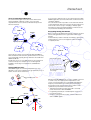
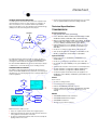
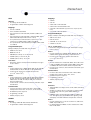
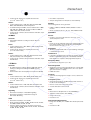
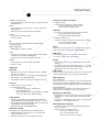
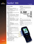
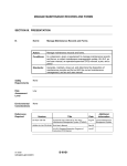
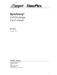
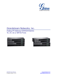
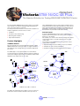
Datasheet
VictoriaSTM-16/OC-48 Plus
The Smartest Solution for Testing SDH/SONET/ATM/PDH/T-Carrier
The Victoria STM-16/OC-48 Plus has all the features of a portable
tester. Thanks to its small size and light weight, this battery-fed
tester is the ideal solution for field work.
The unique measurement features of Victoria make it suitable for a
number of applications, both in and out of service:
•
•
•
•
above ATM Adaptation Layers 2 and 5 (AAL-2 and AAL-5). The Iu
and the Iub interfaces use the AAL-2 and AAL-5 to carry both user
traffic and control traffic. By generating and emulating AAL2 and
AAL5 traffic, commissioning of connections as well as in-service
measurements are performed on 3G mobile networks.
Installation
Remote Control
Acceptance and commissioning
A Victoria STM-16/OC-48 Plus tester can be controlled from
anywhere in the world, thanks to the remote control system that
makes use of the Internet.
Monitoring and surveillance
Repair and maintenance
This enables you to test the whole network, manage and compare
results and give help to your field technicians from one single
control centre.
Product Highlights
The following can be highlighted from among the basic remote
control features of Victoria:
3G/UMTS Network
Telecom networks have evolved towards the integration of SDH/
SONET, ATM and IP technologies under one single architecture,
thus making it easier to bring today’s new telematics applications
into service.
•
•
•
Graphical interface based on intuitive, easy-to-use windows
Simultaneous control of many instruments
Client/Server architecture fully integrated into the Internet
The UMTS (3G) is a very typical example of a network where
several technologies are merged, and these need to be separetely
tested. After testing the physical layer, the ATM layer and the ATM
Adaptation Layer (AAL) must also be tested.
ADM
ADM
OC-48
Victoria
MSC
Circuit
Switched
Network
E1
Node B
RNC
Victoria
RClient
STM-1
Victoria
TCP/IP
POTS
STM-1
Victoria
STM-1
SGSN
E1
Node B
RServer
Packet
Switched
Network
RNC
ATM in E1, E3, STM-1... interfaces
The 3GPP (3G Partnership Project) defines a rich set of protocols
between the end user and other networks. These protocols sit
TrendCommunications
RClient
Datasheet
2
Tests in International Gateways
The current technological needs call for testers that meet the
varying standards of different countries. It is an essential
requirement that a tester can interact with both European and
American interfaces.
It is necessary to define the type of error and the part of the SDH/
SONET signal affected, to find out which link or network element is
causing the problem.
The scan function makes it possible to locate and isolate network
events automatically. This function works at any hierarchical level,
and it can be used for any type of mapping or tributary signal.
The path trace analysis and TCM capabilities of Victoria are also
very useful when identifying the affected link.
SONET
Evaluating Analog Parameters
Victoria
Before carrying out any digital measurements, it must be checked
that the analog parameters of the signal remain within certain
margins.
Victoria
Victoria makes it possible to instantly check that the optical power
and the frequency of the received signal are within the margins
accepted by the ITU.
High capacity DXC
SDH
SONET
Network
Victoria has the capacity to work with both SDH and SONET or
PDH and T-Carrier at the same time, and this makes it a necessary
tool in testing high-capacity gateways that interconnect SDH and
SONET backbones.
Ideal incoming signal
Besides this, the use of some ANSI interfaces is becoming more
common in Europe. For example, the use of DS3 signals at
45 Mbit/s is increasing in such applications as MPEG video
transport.
Incoming signal power
too low
Alarm and Error Scan
SDH/SONET signals are formed by multiplexed lower order
tributaries. Some of these tributaries may get affected by errors or
alarms, whereas others remain intact.
Incoming signal frequency
out of range
Victoria
C
B
Unavailable path: AIS
E3
E3
With Victoria STM-16/OC-48 Plus, it is safe to establish connection
to a link to carry out an optical power measurement, as the
receiver is protected against any overload that might damage it.
ADM
A
Frequency measurements are not limited only to presenting
measurement results in Hertz, but it is also possible to make
sophisticated synchronization measurements:
E3
STM-1
DXC
•
TIE (Time Interval Error) measurement; TIE is caused by
pointer movements in SDH and SONET
•
Programming and analysis of standard pointer sequences, to
test network tolerance
•
Frequency offset generation in PDH / T-Carrier tributaries in
SDH or SONET signals.
Victoria
STM-1
SCAN
Path A: OK
Path B: OK
Path C: E3 AIS
ADM
E3
E3
E3
B
A
C
Datasheet
3
•
Tandem Connection Monitoring
In a multi-operator environment, there are some companies that
offer transmission services of other operators or companies. In
these circumstances, it is essential to delimit responsibilities
whenever a problem occurs. The Tandem Connection Monitoring
(TCM) protocol has been designed for this purpose.
Create new specialized measurements that the user can create,
such as repetitive BERT used when installing radio links
Technical Specifications
TRANSMISSION
Electrical Interfaces
ERRORS
Operator C
Operator B
SDH/SONET
TCM
events
Operator A
•
•
BNC (default), DIN 1.6/5.6 (option DIN55)
•
Optional: 1544 kbit/s B8ZS and AMI (option 30554), 44736 kbit/
s B3ZS & AMI (option 30552), pulses DS3-HI and DSX-3 (with
accessory AD045), 51840 kbit/s B3ZS (option 30551)
•
Balanced Bantam (accessory AD300), Siemens (accessory
AD320) and RJ48 (accessory AD322) for 1544 kbit/s and
2048 kbit/s
•
•
Interfaces according to G.703, ANSI T1.102 and G.772
Rates: 2048 kbit/s HDB3 and AMI, 8448 kbit/s HDB3 and AMI,
34368 kbit/s HDB3, 139264 kbit/s CMI, 155520 kbit/s CMI
Gain: 0, 20, 26, 30 dB from 1544 kbit/s to 51840 kbit/s; 0, 20,
26 dB for 139264 kbit/s and 0, 20 dB for 155520 kbit/s
Optical Interfaces
The TCM mechanism makes it possible to analyse the part of
the path where a problem occurs when an SDH/SONET signal is
crossing the network and arrives degraded at its destination.
The Victoria STM-16/OC-48 Plus generates and analyses all type
of TCM events to check that this protocol is working correctly.
Automatic Measurements
The ability to make automatic measurements by using macros
makes Victoria STM-16/OC-48 Plus a powerful tool in carrying out
repetitive tests, such as bringing-into-service and type approval of
network equipment.
•
Built-in connectors for 155520 kbit/s, 622080 kbit/s and
2488320 kbit/s
•
•
Interfaces according to the ITU-T G.957 L-16.1 and L-16.3
•
•
Automatic disconnection of the receiver for overload protection
•
Via external optical micromodules fed by the equipment for
34368 kbit/s (option 305531), 51840 kbit/s (option 305511), and
155520 kbit/s
FC (default), SC (option 3090SC) or ST (option 3090ST) connectors
1310 nm transmitter (configurations 3095C1, 3095C4) and
1550 nm transmitter (configurations 3095C2, 3095C4)
Clock
Clock sources
SES<S2
•
•
•
•
ISM
PASS
PHASE 3
Internal, according to G.812
Recovered from the incoming signal
External 1544/2048 kHz with BNC connector
External coded G.703 at 1544 kbit/s and 2048 kbit/s with BNC
or balanced connector with 0 and 20 dB gain (accessory
AD340)
Modes
ES<S1
ES<S2
PASS
FAIL
With the the macro utility you can:
•
•
Carry out complex measurements with a single keypress
•
Program customized pass/fail tests that show the result by displaying a label on the screen
Help field technicians throughout the measurement, by means
of the graphical user interface of the tester
•
•
•
•
SDH/SONET/PDH//T-Carrier termination
SDH/SONET/PDH/T-Carrier, bridged
SDH/SONET mux/demux
Through mode for all the interfaces
Datasheet
4
SDH
•
•
•
•
•
STS-48c
C-4-4c in STM-4 and STM-16
•
VT-1.5 bulk or with framed DS1
General
•
•
Mappings
According to G.707 and O.181
Programmable scrambler and background
Mappings
STS -12c
STS-3c bulk or with framed E4
STS-1 bulk or with framed DS3 or E3
VT-2 bulk or with framed E1 (asynchronous or byte synchronous)
•
•
•
C-4-16c in STM-16
C-4 (unstructured or with framed E4) in STM-1, STM-4 and
STM-16.
Programmable Bytes
•
C-3 (unstructured or with framed E3 or DS3) in STM-0, STM-1,
STM-4 and STM-16 (both with an AU-3 or AU-4)
•
C-12 (unstructured or with framed E1, asynchronous or byte
synchronous) in STM-0, STM-1, STM-4 and STM-16
•
C-11 (unstructured or with framed DS1) in STM-0, STM-1, STM4 or STM-16
•
•
•
•
Programmable Bytes
Editing and display in hexadecimal or by descriptor
•
•
•
•
•
Display of all bytes and editing in hexadecimal or by descriptor of:
SOH: A1, A2, J0, C1
LOH: K1, K2, S1
STS-POH: J1, C2, G1, H4, K3
VT-POH: J2, V5, K4
J0, J1, J2 Trail Trace
•
RSOH: A1, A2, J0, C1
Generation, analysis and expected 16- and 64-byte messages
in J0, J1 and J2
MSOH: K1, K2, S1
Errors
HO-POH (VC-4, VC-3): J1, C2, G1, H4, K3
•
Insertion and detection of ECOD, EFAS, SEF, B1, B2, REI-L,
STS-B3, REI-P, VT-B3, REI-V, BIP-2, slip and bit errors
•
Insertion mode: single, burst, repetitive burst and rate
(1.1 x 10⁻³ to 0.9 x 10⁻⁹s)
LO-POH (VC-3): J1, C2, G1, H4, K3
LO-POH (VC-12, VC-11): V5, J2, K4
Trail Trace
Alarms
•
•
Insertion and detection of LOS, LOF, TIM-S, AIS-L, RDI-L, AISP, LOP-P, UNEQ-P, RDI-P, TIM-P, PLM-P, LOM-V, AIS-V, LOPV, UNEQ-V, RDI-V, RFI-V, TIM-V, PLM-V, LSS pattern AIS
•
Insertion mode: continuous, burst of M frames with alarm, repetitive M/N burst
Generation, analysis and expected 16- and 64-byte messages
in J0, J1 and J2
Errors
•
Insertion and detection of ECOD, EFAS, OOF, B1, B2, MS-REI,
HP-B3, HP-REI, LP-B3, LP-REI, BIP-2, slips and bit errors
•
Insertion mode: single, burst, repetitive burst and rate
(1.1 x 10⁻³ to 0.9 x 10⁻⁹s)
Alarms
•
•
Insertion and detection of LOS, LOF, RS-TIM, MS-AIS, MS-RDI,
AU-AIS, AU-LOP, HP-UNQ, HP-RDI, HP-TIM, HP-PLM, TULOM, TU-AIS, TU-LOP, LP-UNQ, LP-RDI, RFI, LP-TIM, LPPLM, LSS, pattern AIS.
Insertion mode: continuous, burst of M frames with alarm, repetitive M/N burst
Pointer Events
•
Increment, decrement, manual value with or without NDF,
invalid pointer in AU-4, AU-3, TU-3, TU-2, TU-12 and TU-11
•
•
•
G.783/O.172 pointer sequences
Programming of SS bits
Tributary frequency offset
SONET
General
•
•
Pointer Events
•
Increment, decrement, manual value with or without NDF,
invalid pointer in STS-3c, STS-1, VT-2, VT-1.5
•
•
•
G.783/O.172 pointer sequences
Tributary frequency offset
PDH
Structure
•
140 and 8 Mbit/s according to G.751, G.742, G.704, framed and
unframed
•
34 Mbit/s according to G.751 or optionally according to G.832
for transporting 14 TU-12s (options 30553, 305531), or
unframed
•
PCM30/31 frame structure with/without CRC for 2 Mbit/s signals. Test signal in 64 or N x 64 kbit/s. CAS signalling: setup
and display of the CAS multiframe and spare bits of frame 0
Errors
•
Insertion and detection of code errors, FAS errors, CRC errors,
REBE, slips and bit errors
•
For G.832 framing in 34 Mbit/s, insertion and detection of EM,
REI, LP-REI, BIP-2
According to ANSI.105-1995 and Telcordia GR.253
Programmable scrambler and background
Programming of SS bits
Datasheet
5
•
Insertion mode: single, burst, repetitive burst and rate
(1.1 x 10⁻³ to 0.9 x 10⁻⁹s)
Alarms
•
Insertion and detection of LOS, AIS, LOF, RAI, CRC-LOM,
MAIS, CAS-LOM, MRAI, LSS and AIS pattern
•
For G.832 framing in 34 Mbit/s, insertion and detection of OOF,
LOF, TIM, RDI, UNEQ, PLM, TU-AIS, TU-LOP, TU-LOM, LPUNQ, LP-RDI, RFI, LP-TIM, LP-PLM
•
Insertion mode: continuous, burst of M frames with alarm, repetitive M/N burst
45 Mbit/s
Structure
•
Framed M13 and C-bit according to G.752, G.704, also
unframed
Errors
•
Insertion and detection of BPV, M-BIT, F-PAR, P-PAR, C-PAR,
FEBE, slips and bit errors
•
Insertion mode: single, burst, repetitive burst and rate
(1.1 x 10⁻³ to 0.9 x 10⁻⁹s)
Alarms
•
Insertion and detection of LOS, AIS, LOF, Blue Alarm, IDLE,
RAI (Yellow Alarm), LSS and AIS pattern
•
Insertion mode: continuous, burst of M frames with alarm, repetitive M/N burst
•
•
B3 or BIP-2 compensation
Analysis and generation of APId (Access Point Identifier)
Pattern
The following patterns can be generated:
•
PRBS11, PRBS15, PRBS20, PRBS23, PRBS31: normal or
inverted
•
Word: user defined, all zeros, all ones, 1010, 1000 and 1100
Functions
Results
•
Counters, errored seconds and rate for all events: errors,
alarms and pointer events
Trace
•
Events are shown graphically in time plots and histograms that
have advanced filter, search, identification and quantization
functions and a zoom from 1 s to 1 h
SoftLEDs©
•
10 tricolour external LEDs with on-screen labelling, showing up
to 80 simultaneous events
Performance
•
Performance measurements in line with ITU-T G.821, M.2100,
M.2101.1 and G.826. Counter, rate, unavailability and PASS/
FAIL indication of compliance with programmed objectives
Round Trip Delay
1.5 Mbit/s
•
Structure
Autoconfiguration
•
SF & ESF framing according to ANSI T1-400-1995, SLC-96
framing according to Telcordia TR-TSY-00008, and also
unframed
•
Fractional DS1: DS1 with test pattern in N x 64 & N x 56 kbit/s
Errors
•
•
Identification of the incoming signal parameters: network (SDH,
SONET, T-Carrier, PDH or G.832), bit rate, line code, optimal
gain, frame structure, mapping
•
PRBS autosearch
FastScan
•
Insertion mode: single, burst, repetitive burst and rate
(1.1 x 10⁻³ to 0.9 x 10⁻⁹s)
Transparency Test
Insertion and detection of LOS, LOF, RAI, LSS and line AIS
Insertion mode: continuous, burst of M frames with alarm, repetitive M/N burst
Signalling
•
•
•
Insertion and detection of BPV, EFAS, ECRC and bit errors
Alarms
•
•
In all interfaces; range from 1 µs to 10 s
Generation and analysis of Robbed Bit signalling
Generation and analysis of Data Link messages in
ESF & SLC-96 framing
TCM
Search the incoming signal for all types of errors, alarms and
events
•
Generation and analysis of PRBS pattern in DCC channels or
E1, E2, F1, N1 and N2 bytes
•
•
Bit error counter, rate and errored seconds
Seconds with alarm counter for LSS
APS
•
•
•
•
Measurement of disruption time for any STM-N/OC-N
Tributaries: PDH, T-Carrier, SDH, SONET
Range: 1 ms to 10 s
Resolution: 1 ms
•
•
Generation and analysis of N1 and N2
Optical Power Measurement
Events generated: TC-IEC, TC-OEI, TC-REI, TC-AIS, TC-LTC,
TC-UNEQ, TC-ODI, TC-RDI, TC-TIM
•
Range: 0 to -28 dBm (+2 to -40 dBm with external optical modules)
•
Detection, display, performance calculation and storage of
events: TC-IEC, TC-OEI, TC-REI, TC-AIS, TC-LTC, TC-UNEQ,
TC-ODI, TC-RDI, TC-TIM
•
Resolution: ±1 dB
Datasheet
6
Frequency Measurement
•
•
•
•
Insertion/Detection of invalid pointer and new value with/without
NDF indication
•
Insertion/Detection of increment/decrement of pointer. Manual
or in intervals of between 1ms and 8 hours
In Hertz and bit/s with deviation in ppm
ITU-T/ANSI in-range or out-of-range indication
TIE measurement based on Pointer Justification Events
STS-3c/OC-3c
Frequency Offset of the Transmission Clock
•
Up to 40 ppm in steps of 0.01 ppm for the integrated optical
interfaces
•
Up to 20,000 ppm in steps of 0.01 ppm for electrical interfaces
and for optical interface at 155 Mbit/s with external module
•
SOH, LOH and STS-POH bytes
•
Remote Control
•
•
Editing/Display in hexadecimal or by descriptor of C1, S1, K1,
K2, C2, G1, H4 and K3
Via RS-232C interface and SCPI commands
Trail trace messages J0 and J1
Optional remote control with advanced GUI (option CR3090)
•
Printout of Results
•
According to ANSI T1.105-1995, ATM mapping according to
T1.105.02-1995. Scrambler can be disabled/enabled. Default
value of SS bits = 00
Totals and periods, events (trace, in real time or result files),
header with configuration and results
Generation/Analysis of G.831 messages of 16 bytes with CRC
and ECRC status
Errors
•
Insertion mode - manual, rate, burst, continuous burst: B1, B2,
REI-L, BIP-P, REI-P
Transfer to PC
•
Simultaneously detected with hierarchical inhibition
•
Alarms
Via RS-232C port
Autosave
•
If the mains supply fails, the current context is saved and the
measurement continues when power source is restored
Automatic Measurements and Storing
•
Measurements can last up to 999 days, with automatic
start/stop. They are saved with name/date/time, the configuration of the tester at the time of the measurement and, if desired,
a text comment by the user
•
•
STM-1
Detection of LOS, LOP-P, RDI-P, PLM-P, TIM-P, UNEQ-P
Pointer actions
•
Editing of H1 and H2 value on generation and display of same
on reception
•
Insertion/Detection of invalid pointer and new value with/without
NDF indication
•
Insertion/Detection of increment/decrement of pointer. Manual
or in intervals of 1 ms to 8 hours
ATM
ATM Interfaces
Insertion/Detection of OOF, LOF, TIM-S, AIS-L, RDI-L, AIS- P
DS3
C-bit frame (T1.107-1995), ATM cell mapping options (G.804 &
T1.646-1995): direct mapping or using PLCP subframe.
According to O.181 and G.707. ATM cells mapped according to
I.432.2. Scrambler can be disabled/enabled. Default value of SS
bits = 10
Errors
•
Insertion mode - manual, rate, burst, continuous burst: BPV, Mbit, F-bit, P-bit and C-bit parity, FEBE.
RSOH, MSOH and HO-POH bytes
•
Simultaneously detected with hierarchical inhibition
•
Editing/Display in hexadecimal or by descriptor of C1, S1, K1,
K2, C2, G1, H4 and K3
Trail trace messages J0 and J1
•
Generation/Analysis of G.831 messages of 16 bytes with CRC
and ECRC status
Alarms
•
•
Insertion/Detection of OOF, RAI, AIS, Idle signal
Detection of LOS
Errors PLCP
•
•
Insertion mode - manual, rate, burst, continuous burst: B1, B2,
MS-REI, HP-B3, HP-REI
Insertion mode - manual, rate, burst, continuous burst: PLCP
FAS, PLCPBIP-8, FEBE, errored POI..
•
Simultaneously detected with hierarchical inhibition
•
Simultaneously detected with hierarchical inhibition
Alarms PLCP
Errors
Alarms
•
Insertion/Detection of OOF, LOF, RS-TIM, MS-AIS, MS-RDI,
AU-AIS, AU-LOP, HP-RDI, HP-SLM, HP-TIM, HP-UNEQ
•
Detection of LOS
Pointers
•
Editing of H1 and H2 value on generation and display of same
on reception
•
Insertion/Detection of LOF, RAI, Loss of POI
E3/G.832 structure
Frame according to G.832, ATM cell mapping according to G.804
MA, NR and GC bytes
•
Editing/Display in hexadecimal or by descriptor
Datasheet
7
Trail trace messages TR
Selection of streams for analysis
•
•
•
Generation/Analysis of G.831 messages of 16 bytes with CRC
and ECRC status
Errors
•
Insertion mode - manual, rate, burst, continuous burst: FAS,
REI, EM (BIP-8)
•
Simultaneously detected with hierarchical inhibition
•
Generation of segment and end-to-end F4 and F5 flows:
F4: VP-AIS, VP-RDI, VP-CC, VP-LB
F5: VC-AIS, VC-RDI, VC-CC, VC-LB
Insertion/Detection LOF, AIS, RDI
Detection of LOS
E1
•
•
Frame according to G.704 with CRC-4 and ATM mapping
according to G.804
NFAS, TS16 bytes
•
Selection of payload type for foreground stream:
Selection of AAL0, AAL1, AAL2 or AAL5
O.191, PRBS, word and live traffic
OAM cells
Alarms
•
•
Editing of VPI/VCI
Editing/Display of Si bits and TS16
Errors
•
Insertion mode - manual, rate, burst, continuous burst: HDB3
and AMI code, FAS, CRC-4, REBE (E-bit)
•
Simultaneously detected with hierarchical inhibition
Editing of loopback cells
Detection of segment and end-to-end F4/F5 alarm conditions:
F4: VP-AIS, VP-RDI, VP-LOC
F5: VC-AIS, VC-RDI, VC-LOC
Errors
Insertion mode - manual, rate, burst, continuous burst. Single or
double cell header error, CER, CLR, CMR and CBER
ATM alarms
•
•
Insertion of LCD, All 1s test sequence (P-AIS) and LSS
Detection of LCD, LPAC, P-AIS and LSS
Alarms
Results
•
•
•
Measurements between 1 min and 999 days, with automatic
start/stop
•
All events shown in trace with resolution from 1 s to 1 h. Time
plots and histograms with advanced identification, search and
quantification functions. Filters by type of event
Insertion/Detection of LOF, AIS, RAI, CRC-LOM
Detection of LOS
ATM layer
Generator
•
Mapping of cells in the frames at all physical layers, UNI/NNI
interfaces, byte-aligned
•
•
•
Generation of 2 types of stream: foreground and background
Cell scrambler can be disabled/enabled
Rate adaptation with the insertion of unassigned or idle cells
Test cells
•
•
Editing of GFC, VPI, VCI, PTI, CLP
Programmable payload:
Selection of AAL0, AAL1, AAL2, AAL3/4
(preconfigured) & AAL5.
O.191, full editing in Hex or ASCII, PRBS 215-1, PRBS
223-1, all 1s, all 0s, 1010, 1000, 8-bit word
ATM headers
Count of errored, discarded and corrected cells, seconds affected
and rate. HEC delineation test showing seconds with LCD
QoS monitoring
Error parameters
Count of received, non-conforming, errored, lost and misinserted
cells. Calculation of CER, CLR, CMR, CBER & seconds affected.
Performance parameters: SECBR, SES, ES and Unavailable time.
Delay parameters
CTD, 1-CDV, 2-CDV, IAT. Current, max, min & average values.
Typical deviation & variability coefficient for 2-CDV, IAT
Monitoring of ATM traffic
•
Bandwidth for link and connections: current, max, min and average values in %, cells/s and bit/s. EFCI and CLP bandwidth
indication
•
Histograms of all bandwidths analyzed: link, connections, total
with CLP=1, connection with CLP=1, etc
Traffic profiles
•
Indication of Peak Cell Rate (PCR), Sustainable Cell Rate
(SCR) and Maximum Burst Size (MBS). Resolution of 1 cell/s
•
Foreground stream: CBR, VBR/2CBRs, VBR/on-off, VBR (PCR,
SCR and MBS programming) and UBR
AAL1 Generation & Analysis
•
Background streams: CBR andVBR/2CBRs
•
Generation of AAL1 fields. AAL1 payload filled with PRBS or
fixed test sequence.
•
Analysis (count, seconds with, ratio) of:
Errored cells: SN parity violation
ATM traffic analyzer
Demapping of cells, UNI/ NNI interfaces & HEC delineation
•
Enabling/Disabling of continuity check, cell scrambler and
header correction functions
•
Simultaneous analysis of fore & background streams
Loss of cells: SN hop detected
Misinserted cells: SN out of sequence
Datasheet
8
AAL2 Generation & Analysis
Generation
•
•
3 foreground & 1 background AAL2 connections.
•
•
Editing CPS-Packet header bytes: CID, UUI.
•
Definition of SSETD packet size and editing trailer fields: UUI,
CI & LP.
•
1 foreground filled with PRBS or fixed test sequence. Remaining foreground connections & background with word.
Programming CPS-Packet size and bandwidth for each connection.
Definition of SAP for each AAL2 foreground connection: CPS,
SSSAR, SSETD.
Analysis
General
• Dimensions: 257 x 147 x 70 mm
• Weight: 2.4 kg
• 12 x 9 cm colour touch screen
• Autonomy: 2 hours (two battery packs)
RF/EMI, ESD and Electrical Safety
•
•
•
•
Radiated EMI: EN50081-1
Immunity to EMI: EN 50082-1
ESD: IEC801-2 (±4 kV contact)
Electrical safety: EN61010-1
Environmental conditions
•
Bandwidth of 3 selectable AAL2 connections identified by CID &
UUI (optional) & Total of AAL2 link.
•
Packet size analysis for 3 AAL2 connections at the SAP
selected (CPS-Packet size or SSETD packet size).
•
•
•
•
Analysis of errors: CPS-PDU parity violation, CPS-PDU SN violation, errored HEC CPS-Packet, errored CRC SSETD packet,
SSSAR or SSETD packet length violation.
Ordering Information
AAL5 Generation & Analysis
Operates at 0 to 45 ºC
Storage: -40 to +70 ºC
Humidity: 5 to 90%, without condensation ❒
Base Configurations
Generation
•
Programming of the CPI, CPS-UU fields and selection of packet
size
•
Payload filled with PRBS or fixed test sequence.
3095C1
Victoria STM-16/OC-48 Plus 1310nm FC/PC.
Colour Handheld Analyser/Generator 2, 8, 34,
140, 155, 622 Mbit/s. Optional 2488, 52, 45, 1.5,
34 Mbit/s (G.832), adv. features, ATM over 2,
34,45 & 155 Mbit/s
3095C2
Victoria STM-16/OC-48 Plus 1550nm FC/PC.
Colour Handheld Analyser/Generator 2, 8, 34,
140, 155, 622 Mbit/s. Optional 2488, 52, 45, 1.5,
34Mbit/s (G.832), adv. features, ATM over 2,
34,45 & 155 Mbit/s
3095C4
Victoria STM-16/OC-48 Plus 1310 & 1550nm
FC/PC. Colour Handheld Analyser/Generator 2,
8, 34, 140, 155, 622 Mbit/s. Optional 2488, 52,
45, 1.5, 34 Mbit/s (G.832), adv. features, ATM
over 2, 34,45 & 155 Mbit/s
Analysis
•
Bandwidth of AAL5 packets in packets/s and bytes/s, current,
maximum, minimum and mean value. Size value of the received
AAL5 packets, current, maximum and minimum.
•
Error Analysis: CPI fields, maximum length exceeded, incorrect
lenght, abort function and CRC error
Functions
Autodetection VPIs/VCIs
Identification of active VPIs/VCIs
Detection of AAL type
Automatic identification of AAL
Options
Scan of specific cells
Transmission Options
Unassigned, OAM, ILMI
Selective capture
30955
STM-16/OC-48 TEST
Cell capture with filtering by header value. Display of contents with
AAL decoding. Time-stamp showing interval between captures
30551
STS-1/STM-0 Electrical Test
IP layer
305511
OC-1/STM-0 Optical Test
Functions performed by Victoria and a PC running software
module:
30552
DS-3 Test
•
•
•
•
30553
G.832 34 Mbit/s Electrical Test
Ranked list of IP addresses
305531
G.832 34 Mbit/s Optical Test
Use of bandwidths
30554
DS-1 Test
Traffic composition by protocol (TCP, UDP, ICMP, IGMP...) and
by application (WWW, FTP, Telnet, DNS, SNMTP...)
30561
Advanced options (TCM, M/N alarms, G.783
sequences, tributary offset)
CR3090
Remote control with graphical user interface
•
IP Ping (RFC 1483/1577)
Size and frequency of IP, TCP and UDP packets
Filters can be programmed to capture traffic for one single VCC
connection or a range of connections.
Datasheet
9
ATM Options
40801
ATM generation & analysis (it includes 2, 34 and
155 Mbit/s)
40702
Extends ATM capabilities over 45 Mbit/s
40802
Adds AAL2 generation & analysis
40805
Adds AAL5 generation & analysis
IPProbe
PC software for statistical analysis of IP traffic
over ATM
CP2ST
Optical cable 2 m with ST/ ST connectors
CPFC2SCPC
Optical cable 2 m with FC-PC/SC-PC connectors
Contact Trend Communications for information on additional options and accessories
Portable, battery-powered printer
AD045
6 dB Line Simulator for 45 Mbit/s
AD210
High impedance attenuating probe
AD300
Balun Adapter 75 Ω BNC to 100 Ω Bantam Jack
AD320
Balun Adapter 75 Ω BNC to 120 Ω Siemens
AD322
2 Mbit/s Balun Adapter 2 x BNC 75 Ω to RJ-48
AD340
Coded 1544 and 2048 kbit/s External Clock 0
and -20 dB for 1544 kHz, 2048 kHz, 1544 kbit/s
and 2048 kbit/s
AD10FC
FC aerial 10 dB attenuator m-f
AD15FC
FC aerial 15 dB attenuator
BT410
Ni-MH battery pack
MOCD3095
User manual
UG3095
English Quick User Guide
UG3095S
Spanish Quick User Guide
MS3095
English Service and Calibration Manual for
Victoria STM-16/OC-48 Plus 3095C
CA220
75 Ω BNC(m) - BNC(m) coaxial cable 2 m
CA230
75 Ω BNC(m) - BNC(m) coaxial cable 2 m
CA231
75 Ω BNC(f)-DIN 1.6/5.6(m) coaxial cable 2 m
CA232
75 Ω BNC(m)-DIN 1.6/5.6(f) coaxial cable 2 m
CA260
RS-232C cable for remote control sub-D
9 (f) - 9 (m)
CP2FC
Optical cable 2 m with FC-PC/FC-PC connectors
CP2SC
Optical cable 2 m with SC/SC connectors.
Trend Communications S.L.
Pujades 60
08005 Barcelona, España
TrendCommunications
web: www.trendcomms.com
e-mail: [email protected]
International..+44 (0) 1628 524977
UK.......................... 01628 524977
España...................... 93 300 3313
Deutschland........ 089 32 30 09 11
France....................01 69 35 54 70
India........................22 8597 463/4
US........................... 256 461 0790
TrendCommunications Ltd reserves the
right to change their product
specifications without prior notification.
This document is for information only and
does not represent a contractual
obligation.
A Member of the Telemetrix plc
These specifications are subject to change without prior notice
PR100.1
ds.va3095.03.uk / 02-09-02
Main Accessories and Replacement Items