1
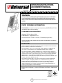
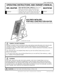
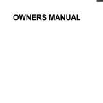
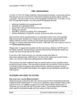
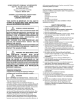
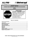
OPERATING INSTRUCTIONS
AND OWNER’S MANUAL
Model # 35-R
READ INSTRUCTIONS CAREFULLY: Read and follow all instructions. Place instructions in a safe
place for future reference. Do not allow anyone who has not read these instructions to assemble,
light, adjust or operate the heater.
GAS-FIREDINFRA-RED
PORTABLECONSTRUCTIONHEATER
DO NOT LEAVE HEATER UNATTENDED OR IN OPERATION WHILE SLEEPING
CYLINDER NOTINCLUDED
GENERAL HAZARD WARNING:
FAILURETO COMPLYWITH THE PRECAUTIONSAND INSTRUCTIONS PROVIDED WITHTHIS HEATER
CAN RESULT IN DEATH, SERIOUS BODILYINJURYAND PROPERTYLOSS OR DAMAGE FROM
HAZARDS OF FIRE, EXPLOSION, BURN,ASPHYXIATION, CARBON MONOXIDE POISONING,AND/OR
ELECTRICALSHOCK.
ONLY PERSONS WHO CAN UNDERSTANDAND FOLLOW THE INSTRUCTIONS SHOULD USE OR
SERVICETHISHEATER.
IF YOU NEEDASSISTANCE OR HEATER INFORMATION SUCHAS INSTRUCTION MANUALS, LABELS,
ETC., CONTACTTHE MANUFACTURER.
WARNING:
FIRE, BURN, INHALATIONAND EXPLOSION HAZARD. KEEP SOLID COMBUSTIBLES SUCHAS
BUILDING MATERIALS, PAPER OR CARDBOARDASAFE DISTANCEAWAY FROM THE HEATERAS
RECOMMENDED BYTHE INSTRUCTIONS. NEVER USE THE HEATER IN SPACES WHICH DO OR MAY
CONTAIN VOLATILE ORAIRBORNE COMPUSTIBLES OR PRODUCTS SUCHAS GASOLINE, SOLVENTS,
PAINTTHINNER, DUST PARTICLES OR UNKNOWN CHEMICALS.
WARNING: NOT FOR HOME OR RECREATIONALVEHICLE USE
04/03 Revision L1 #18675
VENTILATION
SPECIFICATIONS
MODEL NO. ............ 35-R
WARNING
GAS TYPE ......... LP-Gas
MAX. INLET
PRESSURE. ......... 22 in. w.c.
THIS APPLIANCE IS UNVENTED AND MUST BE
USED ONLY IN AWELL VENTILATEDAREA.
MIN. INLET
PRESSURE .......... 22 in. w.c.
The flow of combustion and ventilation air must not be
obstructed. DO NOT use in a tightly enclosed area. Any
combustion process requires and consumes oxygen, and may
produce carbon monoxide. This heater must be operated with
adequate ventilation. Two openings directly to the outdoors must
be provided, one low and one high, preferably on opposite sides
of the area to be heated. Each of these openings must provide at
least three square inches of combustion air-intake area and
exhaust outlet area for every 1000 BTUs per hour of heater input
rate in order to complete the combustion/ventilation process.
Provide additional ventilation for any additional fuel-burning
appliances and/or additional occupants.
MANIFOLD
PRESSURE .......... 21 in. w.c.
Do not exceed the gas supply pressures shown on rating plate
for Model 35-R. The maximum inlet gas supply pressure
and the minimum inlet gas supply pressure (for purposes
of input adjustment) for LP-Gas are shown as follows:
WARNING
DO NOT EXCEED 0.78 psi (22” w.c.) GAS
PRESSURETOTHEGASCONTROLVALVE.
CLEARANCE (Minimum clearances to combustible materials)
MODEL NO.
BTU/HR RATING
TYPEGAS
NATURAL
35-R
LP & NG
35,000*
NORMALOPERATING
POSTION
VERTICAL
CLEARANCESTO
COMBUSTIBLES
TOP
40”
SIDES
40”
BACK
0”
FRONT
54”
*Tank size and tank temperature can directly affect BTU output
CONTENTS
FORYOUR SAFETY
Installation Instructions .................................................. 3
Do not use this heater in a space where
gasoline or other liquids having flammable
vapors are stored or used.
Location ....................................................................... 3
Piping .......................................................................... 3
Odor Fade Warning ..................................................4
The heater is designed and approved for use as a construction
heater under ANSI Z83.7 / CGA 2.14 - 2000
Operating Instructions .................................................. 5
We cannot anticipate every use which may be made of our
heaters. CHECK WITH YOUR LOCAL FIRE SAFETYAUTHORITY IF
YOU HAVE QUESTIONSABOUTAPPLICATIONS.
Lighting and Shut Down ............................................... 5
Maintenance Instructions ............................................. 6
Other standards govern the use of fuel gases and heat producing
products in specific applications. Your local authority can advise
you about these.
Replacement Parts List ............................................... 8
Service and Parts Ordering Information ........................ 9
This appliance is intended to be used primarily for the heating of
buildings under construction, alteration or repair.
THE STATE OF CALIFORNIAREQUIRESTHE FOLLOWING WARNING:
WARNING
Combustion by-products produced when using this product contain
carbon monoxide, a chemical known to the State of California to
cause cancer and birth defects (or other reproductive harm).
2
Operating Instructions and Owner’s Manual
GENERAL INFORMATION
A.
Your 35-R portable gas-fired infra-red heater comes
fully assembled and is tested at the factory for proper
gas and input as stated on the nameplate.
B.
Each heater is equipped with a 100% safety shutoff,
push button valve which will automatically stop the flow
of gas in the event the heater fails to operate for any
reason. A tip over switch and an excess flow check are
also standard on the model 35-R.
C.
The minimum ambient temperature rating for this heater is
20 degrees F.
This heater incorporates a “Tip Over” switch which
automatically shuts off the burner in the event of tipping.
Ensure that this switch is in the vertical position and is
secured with the screws provided (see Fig. 4). DO NOT
operate this heater with the LP-gas supply cylinder in any
other than the upright position.
LOCATION
Although this heater incorporates a “tip over” switch, the heater
and LP-Gas supply cylinder must be located on a hard, flat, level
surface to minimize the risk of accidental tipping. The LP Gas
supply cylinder should be adequately restrained to prevent
accidental tipping. DO NOT OPERATE this heater with the
supply cylinder in any other than the upright position.
Before proceeding with this installation, be sure to
inspect for damages. The freight company must be
notified of any damages and request that an inspection
be made. We will send replacements for damaged
parts only after receiving a signed inspection report to
prove the liability of the freight company.
This appliance must be installed only in locations where the
potential for physical damage to the appliance (i.e., due to
physical contact) is reduced to a minimum.
FOR SAFE OPERATION
A.
B.
READ THESE INSTRUCTIONS CAREFULLY. Read and
adhere to these instructions. DO NOT allow anyone
who has not read these instructions to assemble, light,
adjust or operate this heater.
The installer must inform the owner/operator of this appliance
that precautions must be taken to protect the appliance from
physical damage.
LP-Gas IS HIGHLY FLAMMABLE. In the event of a leak, LPGas will accumulate and the possibility of a fire is present.
LP-Gas is scented and its strong odor is readily detectable.
Never strike a match, bring any flame or create an electric
spark in an enclosure when you smell LP-Gas. Read
enclosed Odor Fade and Propane Sheet for additional
information about detecting propane leaks. Ventilate
the area thoroughly, move the heater outside, and
correct the source of the leak before attempting to light
any appliance.
C.
Always operate the heater with the LP-Gas cylinder in
an upright position on a level non-combustible surface.
NEVER PLACE THE CYLINDER ON ITS SIDE WHEN
OPERATING THE HEATER.
D.
DO NOT attempt to operate the heater with any gas
other than that indicated on the heater nameplate.
This appliance produces radiant heat. Therefore, it must be
located at least six feet away from any LP-Gas container and
must not be directed toward any LP-Gas container within 20 feet.
The heater must be installed in a location such that it will not be
exposed directly to water spray, rain, and/or dripping water.
Use of this heater in a draft/windy area may decrease its
efficiency. If possible, operate the unit in a draft free area or
turn the face of the heater away from the draft.
Due to high surface and exhaust temperatures, adults
and children must odserve clearances to avoid burns or
clothing ignition.
PIPING:
For Model 35-R
(for use with LP-Gas)
This model may be connected to a self-contained LP-Gas supply
system using the hose and regulator assembly supplied with the
appliance, OR, it may be connected to a permanently installed
LP-Gas supply system.
INSTALLATION INSTRUCTIONS
GENERAL
For the U.S. and/or Canada, the installation of this
appliance must comply with local and/or Provincial codes
or, in the absence of these codes,
•
•
If connected to a self-contained LP-Gas supply system, the hose
assembly must be inspected prior to each use of the heater. If it
is evident that there is excessive abrasion or wear, or the hose is
cut, it must be replaced prior to the heater being put into
operation.
With the (U.S.) National Fuel Gas Code, ANSI Z223.1 –
Latest Edition, AND with the (U.S.) Standard for the Storage
and Handling of Liquified Petroleum Gases, ANSI/NFPA 58,
OR
If connected to a self-contained LP-Gas supply system, the
cylinder must have no less than a minimum capacity of 20
pounds and no more than a maximum capacity of 100 pounds of
LP-Gas. DO NOT connect this appliance to a cylinder having less
than a nominal 20 pound capacity of LP-Gas. DO NOT connect
this appliance to more than one (1) 100 pound cylinder.
With the current (Canadian) CAN/CGA B149.1 AND B149.2
INSTALLATION CODES.
This heater (including hose and regulator assembly) must be
inspected before each use and at least annually by a qualified
service person. If the hose for Model 35-R / shows evidence
of excessive abrasion or wear, or if the hose is cut, it must
be replaced prior to the heater being put into operation. The
replacement hose assembly shall be that specified by the
manufacturer. See the parts list.
WARNING
NEVER USE A FORK LIFT TRUCK TYPE
CYLINDER.
3
Operating Instructions and Owner’s Manual
ODOR FADE WARNING
heater dataplate, or contact the Scheu Products Company to
determine combustion air ventilation requirements of the
heater.
• Lack of proper ventilation air will lead to improper
combustion.
• Improper combustion can lead to carbon monoxide
poisoning leading to serious injury or death. Symptom of
carbon monoxide poisoning can include headaches
dizziness and difficulty in breathing.
WARNING
Asphyxiation Hazard
• Do not use this heater for heating human living quarters.
• Do not use in unventilated areas.
• The flow of combustion and ventilation air must not be
obstructed.
• Proper ventilation air must be provided to support the
combustion air requirements of the heater being used.
• Refer to the specification section of the heater’s manual,
FUEL GAS ODOR
LP gas and natural gas have man-made odorants added specifically for detection of fuel gas leaks.
If a gas leak occurs you should be able to smell the fuel gas. Since Propane (LP) is heavier than air you should smell for the gas
odor low to the floor. ANY GAS ODOR IS YOUR SIGNAL TO GO INTO IMMEDIATE ACTION!
areas. When you have reason to suspect a propane leak, keep
• Do not take any action that could ignite the fuel gas. Do not
out of all low areas.
operate any electrical switches. Do not pull any power
supply or extension cords. Do not light matches or any other • Use your neighbor’s phone and call your fuel gas supplier and
your fire department. Do not re-enter the building or area.
source of flame. Do not use your telephone.
• Stay out of the building and away from the area until declared safe
• Get everyone out of the building and away from the area
by the firefighters and your fuel gas supplier.
immediately.
•
FINALLY,
let the fuel gas service person and the firefighters check
• Close all propane (LP) gas tank or cylinder fuel supply
for escaped gas. Have them air out the building and area before
valves, or the main fuel supply valve located at the meter if
you return. Properly trained service people must repair any leaks,
you use natural gas.
check for further leakages, and then relight the appliance for you.
• Propane (LP) gas is heavier than air and may settle in low
ODOR FADING - NO ODOR DETECTED
• Some people cannot smell well. Some people cannot smell the
odor of the man-made chemical added to propane (LP) or
natural gas. You must determine if you can smell the
odorant in these fuel gases.
• Learn to recognize the odor of propane (LP) gas and natural
gas. Local propane (LP) gas dealers will be more than
happy to give you a scratch and sniff pamphlet. Use it to
become familiar with the fuel gas odor.
• Smoking can decrease your ability to smell. Being around
an odor for a period of time can affect your sensitivity to that
particular odor. Odors present in animal confinement
buildings can mask fuel gas odor.
• The odorant in propane (LP) gas and natural gas is
colorless and the intensity of its odor can fade under
some circumstances.
• If there is an underground leak, the movement of gas
through the soil can filter the odorant.
• Propane (LP) gas odor may differ in intensity at different
levels. Since Propane (LP) gas is heavier than air, there may
be more odor at lower levels.
• Always be sensitive to the slightest gas odor. If you
continue to detect any gas odor, no matter how small, treat it
as a serious leak. Immediately go into action as discussed
previously.
ATTENTION - CRITICAL POINTS TO REMEMBER!
• Propane (LP) gas has a distinctive odor. Learn to recognize
these odors. (Reference Fuel Gas Odor and Odor Fading
sections above.
• Even If you are not property trained in the service and repair
of the heater, ALWAYS be consciously aware of the odors of
propane (LP) gas and natural gas.
• If you have not been properly trained in repair and service of
propane (LP) gas then do not attempt to light heater,
perform service or repairs, or make any adjustments to the
heater on the propane (LP) gas fuel system.
• A periodic sniff test around the heater or at the heater’s
joints; i.e. hose, connections, etc., is a good safety practice
under any conditions. If you smell even a small amount of
gas, CONTACT YOUR FUEL GAS SUPPLIER IMMEDIATELY.
DO NOT WAIT!
4
Operating Instructions and Owner’s Manual
The connection of Model 35-R to an LP-Gas cylinder must
be made in a well ventilated area using the regulator and
hose assembly supplied with the appliance. DO NOT
attempt to adjust this regulator. It has been preset at the
factory to provide safe and proper operation of the
appliance. Use a 7/8” open end wrench to connect the
POL fitting (supplied with the LP regulator) to the LP-Gas
cylinder. Turn the POL nut in a counter-clockwise
direction (left hand thread) until tight. DO NOT use pipe
compound on POL threads.
CAUTION
DO NOT PLACE CLOTHING OR
OTHER COMBUSTIBLE
ATERIALS ON THIS APPLIANCE.
DO NOT operate this heater if any part has been under
water. Call a qualified service technician to inspect the
appliance and to replace any part of the control system or gas
control valve which has been under water.
The heater must be located at least six feet away from any
LP-Gas cylinder and must not be directed toward any LPGas cylinder within 20 feet. If more than one heater is used,
they and the supply cylinders must be separated by at least
20 feet.
This appliance must be installed and operated only in
locations where the potential for physical damage to the
appliance is reduced to a minimum. The owner/operator of
this appliance must ensure that precautions are taken to
protect the appliance from physical damage.
The gas supply must be turned off at the LP-Gas supply cylinder
when the heater is not in use.
When the heater is to be stored indoors, the connection
between the LP-Gas supply cylinder and the heater must be
disconnected and the cylinder removed from the heater and
stored in accordance with Chapter 5 of the Standard for the
Storage and Handling of Liquefied Petroleum Gases, ANSI/NF-PA
58 (U.S.), OR CAN/CGA B149.2 (Canada).
LIGHTING AND SHUT-DOWN
Lighting the Heater:
If connected to a permanently installed LP Gas supply system,
the system requires the use of a two-stage gas regulator
assembly which is normally provided by your LP-Gas dealer as
part of the LP-Gas supply system. Consult with your local LP-Gas
dealer for details concerning proper equipment and installation.
1.
Before attempting to light the heater, smell all
around the heater area for gas. Be sure to smell
next to the floor because LP-Gas is heavier than
air and will settle on the floor. Turn on the gas
supply to the appliance and check all fittings and
connections for gas leaks using a mild soap and
water solution. Read enclosed Odor Fade and
Propane Sheet for additional information about
detecting propane leaks. NEVER use a match to
check for gas leaks. Should a gas leak occur, shut
off the gas supply to the appliance immediately.
Wait a minimum of five minutes before repairing
the leak.
2.
Use only the fuel intended for this appliance.
Check the appliance rating plate for the correct fuel
information.
3.
Turn off the main gas supply to the appliance. Wait
five minutes.
4.
Turn on the main gas supply.
Piping must be clean and free from scale or burr.
Before attempting to ignite the appliance, all gas fittings and
connections must be thoroughly checked for gas leaks. Apply a
small amount of a mild soap and water solution to all fittings
and connections and observe for escaping bubbles. If any leaks
are detected, shut off the gas supply to the appliance
immediately. Wait a minimum of five minutes, repair the leak(s)
and retest for leakage. Dry all fittings and connections after
leak testing.
WARNING
NEVER USE A FLAME FOR GAS LEAK TESTING.
OPERATING INSTRUCTIONS
5a. Depress and turn Control Knob counterclockwise to
“Pilot” position and hold for 1-2 minutes. This may take
longer to purge air from the supply hose depending on
the length of the hose being used.
WARNING: IF YOU DO NOT FOLLOW
Depress red spark ignition button to light pilot flame
(repeat until pilot lights) and continue to hold Control
Knob at “Pilot” positionfor 30-60 seconds to enable
Pilot Light Safety System.
THESE INSTRUCTION EXACTLY, A FIRE
OR EXPLOSION MAY RESULT
CAUSING PROPERTY DAMAGE,
PERSONAL INJURY, OR LOSS OF LIFE.
Fully turn Control Knob to “Hi” position to light burner. or...
5b. With a lighted match held to the burner face, depress
and hold the reset button. After the burner ignites,
hold the reset button depressed for about one minute
or until the burner stays lit when the reset button is
released. DO NOT light the gas at the burner
orifice. DO NOT face heater when attempting to
light. Always stand to the side of the unit when
lighting.
CAUTION:THIS APPLIANCE IS
HOTDURING NORMAL
OPERATION. AVOID PHYSICAL
CONTACT.DO NOT MOVE OR
HANDLE DURING OPERATION
OR UNTIL COMPLETELY COOL.
5
Operating Instructions and Owner’s Manual
NOTE: In cases where long runs of gas supply lineshave
been installed ahead of the appliance, it may be necessary
to bleed trapped air out of the supply lines before lighting
the burner. New installations generally require bleeding of
supply lines. Wait a minimum of five minutes after
bleeding the supply lines before attempting to light the
heater.
6.
•
Clean the orifice of each burner with a #55 drill bit
(for LP-Gas).
•
Clean the thermocouple lead.
DO NOT operate this heater if any part has been under
water. Call a qualified service person to inspect the appliance
and to replace any part of the control system or gas control valve
which has been under water.
This heater must be inspected at least annually by a
qualified service person.
IMPORTANT: DO NOT attempt to adjust the main
burner input using the main gas supply valve, for
this may cause the thermocouple to shut down the
burner.
TROUBLESHOOTING INFORMATION:
(Model 35-R)
Shut-down instructions:
To turn the heater OFF:
If burner lights, but goes out when button is released.
1.
Close the LP-Gas supply cylinder valve.
2.
Observe the burner until flame is extinguished.
CHECK
3.
Listen for closure of the safety valve.
•
Loose wires on tipover switch. (see Fig. 4)
4.
IMPORTANT: DO NOT re-open the LP-Gas supply
cylinder valve before the safety valve closes.
•
Loose lead wire and repair wires if necessary.
•
Loose thermocouple and tighten if necessary.
Make sure T/C is located correctly between the
reverberator and grid.
•
Defective thermocouple. Replace if necessary.
•
Defective control. Replace if necessary.
•
Defective tip over switch. Replace if necessary.
MAINTENANCE INSTRUCTIONS
This heater (including hose and regulator assembly) must be
inspected before each use. If the hose for Model 35-R
shows evidence of excessive abrasion or wear, or if the
hose is cut, it must be replaced prior to the heater being put
into operation. The replacement hose assembly shall be
that specified by the manufacturer. See the parts list.
The appliance area must be kept free and clear of
combustible materials, gasoline and other flammable
vapors and liquids at all times.
The flow of combustion and ventilation air must not be
obstructed.
Expanded Metal Screen
Cleaning the heater:
Cylinder
Gas Valve
Periodically, the heater must be cleaned of all dirt and dust
particles.
Burner Face
Reflector
DANGER
Thermocouple
DO NOTATTEMPTTO CLEAN THE HEATER
WHILE IT IS OPERATING OR WHILE IT IS
STILLHOT.
•
Turn the heater off and wait until it has completely cooled
(at least 20 minutes) before cleaning.
•
Clean the outside of the heater using a damp cloth. DO
NOT clean the heater by spraying water on it. Wipe the
outside of the heater off with a dry cloth after cleaning.
•
Propane
Gas
Cylinder
Orifice
Regulator
Control
Valve
Reet
Button
Hose
NOTE: WHEN LIGHTING BURNER WITH A MATCH OR TAPER,
LIGHT AT BOTTOM OF SCREEN. (NOT AT ORIFICE)
Figure 3
Clean the inside of the heater using compressed air.
Blow air back and forth along the entire burner face
until all dust has been dislodged from the surface of
the reverberator and grid screen. Blow through venturi
from the control end of the heater.
6
Operating Instructions and Owner’s Manual
Tip Over
Switch
Magnetic Portion
of Control
Thermocouple
Adaptor
Leads
Control
Tip Over
Switch
Leads
Junction Block
Adaptor Kit
Heater Bottom
Figure 4
REPLACEMENT PARTS LIST
Tip-Over Switch Arrangement
NOTE: The purpose of the tip-over Switch is to stop the flow
of gas when heater is accidentally knocked over. When and
if the heater is knocked over, simply stand heater up.
REF. # ...... ITEM#
DESCRIPTION
1 ............. 00333 ........ CONT M-N SS PORT 3/8MPXI/4MP
2 ............. 02455 ........ BURNR/LTFR PORTABLES/D1096
3 ............. 05455 ........ ORIFICE/BURNER #55 DRILL
4 ............. 09352 ........ THERMOCOUPLE ASSY/18”
5 ............. 09357 ........ TIP-OVER SWITCH 6” LEAD(PORT)
6 ............. 09371 ........ JUNCTION BLK ADPTR KIT/TIPSW
7 ............. 11695 ........ REC.L/P 21” WC OUT
8 ............. CR705 ....... IGNITOR, MODEL#35
9 ............. CR735 ....... PIEZO, MODEL#35
10 ........... CR710 ....... WHEEL, MODEL#35
11 ............ CR720 ....... AXLE, MODEL#35
12 ........... CR715 ....... AXLE BRACKETS, MODEL#35
13 ........... CR725 ....... HANDLE
14 ........... CR730 ....... WHEEL LOC
15 ........... 70722 ........ MAIN FRAME LOWER ASSEMBLY
7
Operating Instructions and Owner’s Manual
Gas-Fired Infra-Red Portable Construction Heater • Model # 35-R
13
3
2
9
4
5
12
8
10
14
1
11
6
7
IF SERVICE IS REQUIRED
PLEASE DO NOTRETURN THISAPPLIANCETOYOUR STORE
For information regarding service, please call our Toll-Free
Number: 1-888-619-7060
Our office hours are 7:00 AM to 4:00 PM, CT Time Zone,
Monday through Friday
Please include the model number, date of purchase and
description of problem in all communication.
8
Operating Instructions and Owner’s Manual
OPERATING INSTRUCTIONS
AND OWNER’S MANUAL
Model # 35-R
WARNING:
USE ONLYMANUFACTURER’S REPLACEMENTPARTS. USE OFANYOTHER PARTS
COULD CAUSE INJURYOR DEATH. REPLACEMENTPARTSARE ONLYAVAILABLE
DIRECT FROM THE FACTORYAND MUSTBE INSTALLED BYAQUALIFIED SERVICE
AGENCY.
PARTS ORDERING INFORMATION:
PURCHASING: Accessories may be purchased at any SCHEU PROUCTS CO.
local dealer or direct from the factory
FOR INFORMATION REGARDING SERVICE
Please call Toll-Free 888-619-7060
E-Mail Address: [email protected]
Our office hours are 7:00 AM – 4:00 PM, CT, Monday through Friday.
Please include the model number, date of purchase, and description of problem in
all communication.
WARRANTY
SCHEU COMPANY warrants that Infra Red Heaters manufactured and sold will be
free from defects in material and workmanship.
Parts assemblies, controls, etc. furnished by SCHEU PRODUCT COMPANY will
carry a one (1) year warranty on the applicable warranties of the suppliers.
The sole responsibility of SCHEU PRODUCT CO. under this warranty shall be to
replace or repair any part for which a written claim is made to SCHEU PRODUCTS
CO.within the time limit of this warranty which is returned upon request toSCHEU
PRODUCTS CO. F.O.B. RANCHO CUCAMONGA, CA – or F.O.B. any SCHEU
PRODUCTS CO. authorized service facility and which is proved to be defective upon
inspection by SCHEU PRODUCTS CO.
This warranty shall not apply to any part or product which has been subjected to
misuse or neglect, damaged by accident, or rendered defective by reason of
improper installation. THIS WARRANTY IS IN LIEU OF ANY AND ALL OTHER
WARRANTIES, EXPRESSED OR IMPLIED, and of any other responsibility of
SCHEU PRODUCTS CO. for parts or products sold by SCHEU PRODUCTS CO.,
including consequential or special damages.
SCHEU PRODUCTS CO. reserves the right to make changes at any time,
without notice or obligation, in colors, specifications, accessories, materials and
models.
ANSI Z83.7/CGA 2.14-2000
9
Operating Instructions and Owner’s Manual