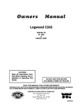
1
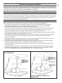
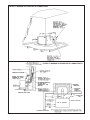
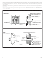
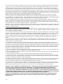
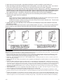
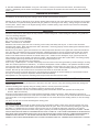
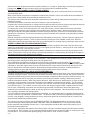
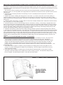
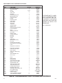
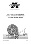
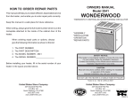
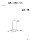
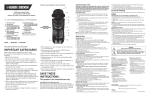
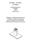
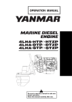
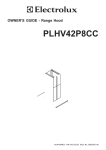
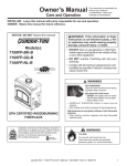
COAL BURNING
CIRCULATOR HEATER
MODEL CAC
website: www.usstove.com
Installation, Operation and Maintenance Instructions
TABLE OF CONTENTS
IMPORTANT SAFETY INFORMATION ............................................................................................................................................................. 1
BUILDING CODES AND SAFETY STANDARDS ............................................................................................................................................. 2
HOW THIS HEATER OPERATES ..................................................................................................................................................................... 2
SELECTING A LOCATION FOR THE HEATER ................................................................................................................................................ 2
FLOOR PROTECTION ..................................................................................................................................................................................... 4
CHIMNEY CONNECTOR AND CHIMNEYS ..................................................................................................................................................... 4
HEATER INSPECTION ..................................................................................................................................................................................... 8
TOOLS AND SUPPLIES NEEDED FOR INSTALLATION ................................................................................................................................ 8
HEATER INSTALLATION .................................................................................................................................................................................. 8
MINIMUM CLEARANCES TO COMBUSTIBLE WALLS AND CEILINGS ................................................................................................... 8
TO SAFELY AND PROPERLY INSTALL THIS HEATER ............................................................................................................................. 9
HEATER OPERATION .................................................................................................................................................................................... 10
TO BUILD A FIRE ..................................................................................................................................................................................... 10
FIRETENDING .......................................................................................................................................................................................... 11
MINIMUM FIRE ADJUSTMENT ..................................................................................................................................................................... 12
COAL FACTS ............................................................................................................................................................................................ 12
HOW TO TAKE CARE OF THE HEATER AND VENTING SYSTEM (ROUTINE MAINTENANCE) ................................................................ 12
HEATER MAINTENANCE ......................................................................................................................................................................... 12
DISPOSAL OF ASHES ............................................................................................................................................................................. 12
VENTING SYSTEM ( CHIMNEY AND CHIMNEY CONNECTOR) ........................................................................................................... 13
CHIMNEY CONNECTOR PIPE-CORROSION INSPECTION .................................................................................................................. 13
TROUBLESHOOTING .................................................................................................................................................................................... 13
THE VENTING SYSTEM-KEY TO GOOD HEATER PERFORMANCE .................................................................................................... 13
WHAT TO DO IF THE HEATER SMOKES, BURNS POORLY OR EXCESSIVE CREOSOTE ACCUMULATES IN THE CHIMNEY ................... 14
WHAT TO DO IF THE HEATER BURNS TO RAPIDLY OR OVERHEATS ................................................................................................. 14
QUICK REFERENCE TO THE MOST COMMON SOLUTIONS FOR THE MOST COMMON HEATER OPERATIONAL PROBLEMS .............. 15
FINAL CHECKLIST OF DO’S AND DON’TS ............................................................................................................................................................ 15
WARRANTY CLAIM INFORMATION AND REPAIR PARTS ...................................................................................................................................... 16
IMPORTANT SAFETY INFORMATION
SAFETY NOTICE: IF THIS HEATER IS NOT PROPERLY INSTALLED, A HOUSE FIRE MAY RESULT. FOR YOUR SAFETY, FOLLOW THE
INSTALLATION INSTRUCTIONS. CONTACT LOCAL BUILDING OR FIRE OFFICIALS ABOUT RESTRICTIONS AND INSTALLATION INSPECTION REQUIREMENTS IN YOUR AREA.
To assure that satisfactory and safe service is received from this heater:
1. Read these instructions entirely before beginning any part of the installation.
2. Use these instructions as a guide during the installation of the heater.
3. Be sure these instructions become the property of and are reviewed by all future users of this heater to encourage proper operation and maintenance of this appliance.
THIS HEATER IS ONLY FOR BURNING COAL. USE OF ANY OTHER SOLID FUEL EXCEPT FOR COAL IGNITION PURPOSES IS A VIOLATION OF FEDERAL LAW.
This heater is designed to burn stove size bituminous or anthracite coal and to provide heat to one or more rooms. Because of its radiating
characteristics, this heater must be installed as an unenclosed, freestanding unit with clearances to combustibles as specified by these instructions.
This heater must be connected to a Listed Factory-Built Residential Type and Building Heating Appliance Chimney or a properly constructed and
maintained masonry chimney.
DO NOT CONNECT THIS UNIT TO A CHIMNEY FLUE SERVING ANOTHER APPLIANCE.
This heater is not designed to burn lignite coal, liquid fuels, and gaseous fuels or household refuse. Any attempt to burn these type fuels, to enclose
the heater or to attach the heater to an air circulation system or a stoking device can be very hazardous.
THIS HEATER IS NOT DESIGNED TO BE USED IN A MOBILE HOME.
Improper installation or use of this heater can cause:
1. Damage to the heater from overheating.
2. Hazardous temperatures to develope on combustible materials adjacent to the heater, chimney connector or chimney.
3. Possible hazardous accumulation of coal gases within the heater.
4. Release of hazardous gas into the dwelling.
CAC
851396 B
1
BUILDING CODES AND SAFETY STANDARDS
These instructions comply with the applicable National Fire Protection Association and Underwriters’ Laboratories, Inc.
Standards for the installation and operation of this type heater. Before beginning the installation, you should check with
local building officials to assure compliance with local regulations and codes.
This heater is safety listed by Warnock Hersey International, Inc. as specified by the listing label attached to the heater.
HOW THIS HEATER OPERATES
The chimney draft draws in combustion air through an adjustable air inlet thermostat located inside the cabinet. Air
flows through and across the bed of fuel, causing the fire to progress through the fuel bed. Heat is transferred to the air
that flows between the cabinet and the firebox. Any attempt to alter this air by connecting this heater to a duct system
or air movement fans other than the optional KB902 listed blower, available from your heater dealer, can lead to improper and possibly hazardous operation of this heater.
SELECTING A LOCATION FOR THE HEATER
When selecting a location for the heater, be sure attention is given to the following considerations:
1. If the heater is to be vented into a Listed High Temperature Type HT Factory-Built Residential Type And
Building Heating Appliance Chimney, review the installation instructions for the chimney to comply with
requirements for proper chimney location, height, space requirements, etc.
2. If the heater is to be vented into a masonry chimney, the heater should be located as near the chimney as possible without failing to comply with the requirements for minimum spacing between the chimney connector,
heater and combustibles. (Be sure chimney is constructed according to NFPA standards.)
3. The location of the heater must provide at least the minimum clearances between the heater, chimney connector
and combustible materials as specified by figures 1, 2, 3, 4.
4. If the heater is to be located on a combustible floor, there must be suitable floor space to install a floor protector
beneath and extending beyond the heater as shown by figure 5 and as described by the Floor Protection
section of this manual.
5. The heater should be located centrally within the area where heat is desired but out of traffic areas to minimize
the likelihood of persons accidentally contacting the hot surface of the heater.
6. The heater should be located away from doorways and central heat outlets and inlets to reduce the chance of
drafts blowing smoke, ashes or sparks out of the heater during refueling or ash removal.
7. The heater should be located where a small supply of wood may be kept conveniently close but not within 36
inches of the heater.
8. Locate the heater so that drapes, curtains, furniture and other combustible materials will not be closer than the
clearances shown by figures 1, 2, 3, and 4 OR install a clearance reduction system. See MINIMUM CLEAR
ANCES TO COMBUSTIBLE WALLS AND CEILINGS section of this manual for details.
FIGURE 1 - MINIMUM CLEARANCES
TO COMBUSTIBLES
FIGURE 2 - MINIMUM CLEARANCES TO
COMBUSTIBLES
2
CAC
FIGURE 3 - MINIMUM CLEARANCES TO COMBUSTIBLES
FIGURE 4 - MINIMUM CLEARANCES TO COMBUSTIBLES
SIDE SECTION VIEW
PLAN SECTION VIEW
CAC
3
FIGURE 5 - FLOOR PROTECTION
FLOOR PROTECTION
This heater has been designed to prevent excessive temperatures on the floor beneath the heater. It is important, however, that
a combustible floor be protected by a 3/8 inch minimum thick noncombustible inorganic millboard having a
thermal conductivity of K=0.43 BTU/ft.2/in./hr./°F or a listed floor protector beneath the heater extending beyond the heater as
shown by figure 5. The floor covering is required to prevent damage or possible ignition from sparks or glowing embers that
might escape the heater during refueling or ash removal or drop from the joints of the chimney connector.
CHIMNEY CONNECTOR AND CHIMNEYS
It is very important to assure safe and satisfactory performance
from your heater that it be properly connected to a correctly
constructed and maintained chimney. If a Listed High Temperature
FIGURE 6 - RISE OF HORIZONTAL
Type HT Factory-Built Residential and Building Heating Appliance
CHIMNEY CONNECTOR PIPE
Chimney is used, follow the chimney manufacturer’s installation
instructions carefully. If a masonry chimney is to be used, be sure
it is constructed to the National Fire Protection Association
(N.F.P.A) and local code standards. A copy of the N.F.P.A 211
RISE:
Chimney, Fireplaces, Vents and solid Fuel Burning Appliances
1/4" FOR EACH FOOT
may be obtained from N.F.P.A., Inc. Batterymarch Park, Quincy, OF CONNECTOR
MA 02269.
LENGTH
The Chimney connector (pipe from heater to chimney) must be
UP
LE
L
NG
A
TA
ON
PE
PI
RIZ
O
H
6 inches in diameter and made from 24 gauge or heavier steel.
TO CHIMNEY
The length of the chimney connector and number of elbows used
should be kept to a minimum. Moisture that might collect in the
ER
chimney should be directed to the heater by providing a slope of
AT
HE
O
1/4 inch per foot in a horizontal run of the chimney connector and
T
installing all pipes with the crimped end toward the heater, (See
figure 6). The chimney connector should extend at least two
inches into the flue of a factory-built chimney. When making a
horizontal connection to a masonry chimney, the connector should
extend to the inside face of the vertical flue liner, (see figures 7 and 8). When connecting the heater to a masonry fireplace, the
chimney connector should extend into the chimney’s liner as shown by the side section view of figure 4. All chimney connector
joints should be sealed with furnace cement and secured with No. 8 sheet metal screws as described by the TO SAFELY AND
PROPERLY INSTALL THIS HEATER section of this manual.
DO NO USE MORE THAN TWO 90 DEGREE ELBOWS IN THE Chimney CONNECTOR. Installations which require two degree
elbows must be vented into a flue of at least 8” diameter or 8” square to prevent chimney draft restrictions, (see figure 2).
DO NOT PASS A CHIMNEY CONNECTOR THROUGH A FLOOR OR CEILING OF ANY KIND. Only Listed Factory-Built Residential Type and Building Heating Appliance Chimneys or masonry chimneys constructed to N.F.P.A. standards should pass through
a floor or ceiling.
4
CAC
There are five allowable ways that a chimney connector can be connected to a masonry chimney by passing
through a combustible wall. NFPA Standard 211 allows the following wall pass-through systems.
1. Use a minimum 3-1/2" thick brick masonry wall framed into the combustible wall. A fireclay liner (ASTM C315 or
equivlent) having a 5/8" minimum wall thickness must be used and it must be at least 12" away from any material that
could catch fire. The inside diameter of the fireclay liner shall be sized for the proper snug fit of a 6" diameter chimney
con nector pipe. The fireclay liner shall run from the outer surface of the brick wall to, but not beyond, the inner surface
of the chimney flue and shall be firmly cemented in place. See Part A of Figure 7.
2. Use a solid insulated listed factory-built chimney length having an inside diameter of 6" and having 1" or more of solid
insulation. There must be at least a 9" air space between the outer wall of the chimney length and any combustible
materials. The inner end of the chimney length shall be flush with the inside of the masonry chimney flue shall be
sealed to the flue and to the brick masonry penetration with nonwater-soluble refractory cement. Sheet steel supports
which are at least 24 gauge(0.024") in thickness shall be securely fastened to wall surfaces on all sides. Fasteners
between supports and the chimney length shall not penetrate the chimney liner. See Part B of Figure 7.
3. Use a 10" diameter ventilated thimble made of at least 24 gauge(0.024") steel having two 1" air channels. The
ventilated thimble must be separated from combustible materials by a minimum of 6" glass fiber insulation. The
opening in the combustible wall shall be covered and the thimble supported with sheet steel supports which are at
least 24 gauge (0.024") in thickness. The sheet steel supports shall be securely fastened to wall surfaces on all sides
and shall be sized to fit and hold the chimney section. Fasteners used to secure chimney sections shall not penetrate
chimney flue liner. See Part C of Figure 7.
4. Use an 8" inside diameter solid insulated listed factory-built chimney length which has 1" or more of solid insulation.
The minimum length of this chimney section shall be 12" and will serve as a pass-through for the 6" diameter chimney
connector. There must be at least a 12" air space between the outer wall of the chimney section and any combustible
materials. The chimney section shall be concentric with and spaced 1" away from the chimney connector by means of
sheet steel support plates on both ends of the chimney section. The opening in the combustible wall shall be covered
and the chimney section supported on both sides with sheet steel supports which are at least 24 gauge (0.024") in
thickness. The sheet steel supports shall be securely fastened to wall surfaces on all sides and shall be sized to fit and
hold the chimney section. Fasteners used to secure chimney sections shall not penetrate chimney flue liner. See Part
C of Figure 7.
5. A listed factory-built wall pass-through system may be purchased and installed according to the instructions packaged
with it to provide a safe method of passing the chimney connector through a combustible wall for connection to a
masonry chimney.
Additional requirements pertaining to Figure 5 and the above wall pass-through systems:
1. Insulation material used as part of wall pass-through system shall be of noncombustible material and shall have a
thermal conductivity of 1.0 Btu • in./ft.² • °F (4.88 kg • cal/hr • m² • °C) or less
2. All clearances and thicknesses are minimums: larger clearances and thickness are acceptable.
3. A chimney thimble, as shown for 3" and 4" above (Parts C and D respectively of Figure 7) shall be for types "3" and "4"
connections to facilitate removal of the chimney connector for cleaning. The chimney thimble shall be of ASTM C315
fireclay with 5/8" minimum wall thickness , or material or equivalent durability. The inside diameter of the thimble shall
be sized for the proper snug fit of a 6" diameter chimney connector pipe. The thimble shall be installed without damage
to the chimney flue. The thimble shall extend through the chimney wall to, but not beyond, the inner surface of the
chimney flue and shall be permanently cemented in place with high temperature cement.
4. A chimney connector to a masonry chimney, except for 2" above (Part B of Figure 7), shall extend through the wall
pass-through system to the inner face of the chimney flue, but not beyond. It does not have to be fastened in place so
long as it cannot accidently be pulled out of the chimney or shoved into the chimney flue. If fasteners are used to
secure the chimney connector to a masonry chimney, the fasteners shall not penetrate the chimney flue liner.
5. Any material used to close up any opening for the connector shall be noncombustible.
If the chimney connector does not have to pass through a combustible wall to get to a masonry chimney, connect the
chimney connector to the masonry chimney as shown in figure 8. The fireclay liner shown by figure 8 should be sized for
the proper snug fit of a 6” diameter chimney connector pipe. The fireclay liner should be firmly cemented in place as
shown. As previously stated, any metal prefabricated chimney this heater is connected to must be a listed Hi-Temp Type
HT Factory Built Residential Type and Building Heating Appliance Chimney.
When a metal prefabricated chimney is used, the manufacturer’s installation instructions must be followed precisely. You must
also purchase (from the same manufacturer) and install the ceiling support packageor wall pass through and “T” section
package, firestops (when needed), insulation shield, roof flashing, chimney cap, etc. Maintain the proper clearance to the
structure as recommended by the manufacturer. This clearance is usually a minimum of 2 inches, although it may vary by
manufacturer or for certain components.
A listed chimney cap should be installed to prevent entrance of rain and help elimnate down drafts. An unapproved chimney
cap, protector or spark arrester can become clogged when leaves or other matter. This blocks the chimney and causes smoke,
and the dangerous carbon monoxide in smoke, to spill back into your home where it can kill you.
CAC
5
There are basically two methods of metal prefabricated chimney installation. One method is to install the chimney inside
the residence through the ceiling and the roof. The other method is to install an exterior chimney that runs up the outside
of the residence.
REMEMBER: Follow the chimney manufacturer's installation instructions and maintain the manufacturer's specified clearance distance.
Additional chimney informationis presented throughout this manual. READ IT THOROUGHLY TO BE MORE THOROUGHLY INFORMED.
CONNECTION OF CHIMNEY CONNECTOR TO A MASONRY CHIMNEY THROUGH A COMBUSTIBLE WALL
PART A, FIGURE 7
(FIGURE 7 CONTINUED ON NEXT PAGE)
MINIMUM CHIMNEY CLEARANCE TO
BRICK AND COMBUSTIBLES IS 2 IN.
CHIMNEY FLUE
MINIMUM CLEARANCES 12
IN. OF BRICK ALL AROUND
MINIMUM 12 IN.
TO COMBUSTIBLES
CHIMNEY CONNECTOR TO
HEATER
FIRE CLAY LINER
(5/8" MIN. WALL THICKNESS)
MASONRY CHIMNEY
CONSTRUCTED TO
NFPA 211
PART B
FIGURE 5 (FIGURE 5 CONTINUED)
MIN. 3-1/2" THICK BRICK
MASONRY WALL
NONSOLUBLE
REFACTORY
CEMENT
AIR SPACE
9 IN. MINIMUM
CHIMNEY LENGTH
FLUSH WITH INSIDE
OF FLUE
AIR SPACE
FACTORY-BUILT
CHIMNEY LENGTH
CHIMNEY FLUE
MINIMUM CHIMNEY CLEARANCES FROM MASONRY TO
SHEET STEEL SUPPORTS AND COMBUSTIBLES 2 IN.
MINIMUM CLEARANCE
9 IN. ALL AROUND
CHIMNEY CONNECTOR
TO HEATER
USE CHIMNEY MFRS. PARTS TO
ATTACH CONNECTOR SECURELY
SOLID INSULATED, LISTED
FACTORY-BUILT CHIMNEY LENGTH
MASONRY CHIMNEY CONSTRUCTED
TO NFPA 211
6
SHEET STEEL SUPPORTS
(24 GAUGE MIN. THICKNESS)
CAC
PART C
FIGURE 5
MINIMUM CHIMNEY CLEARANCES FROM MASONRY TO
SHEET STEEL SUPPORTS AND COMBUSTIBLES 2 IN.
24 GAUGE
VENTILATED THIMBLE WITH
TWO 1 INCH AIR CHANNELS
CHIMNEY FLUE
CHIMNEY THIMBLE
TWO VENTILATED AIR
CHANNELS EACH 1 INCH.
CONSTRUCTED OF
SHEET STEEL.
MASONRY CHIMNEY CONSTRUCTED
TO NFPA 211
PART D
FIGURE 5
CHIMNEY CONNECTOR
TO HEATER
MINIMUM 6 IN. GLASS
FIBER INSULATION ALL AROUND
SHEET STEEL SUPPORTS
(24 GAUGE MIN. THICKNESS)
MINIMUM CHIMNEY CLEARANCES FROM MASONRY TO
SHEET STEEL SUPPORTS AND COMBUSTIBLES 2 IN.
SHEET STEEL SUPPORTS
MINIMUM CLEARANCE
2 IN. ALL AROUND
CHIMNEY SECTION
1 IN. AIR SPACE TO
CHIMNEY LENGTH
CHIMNEY
CONNECTOR
AIR SPACE
2 IN.
CHIMNEY FLUE
CHIMNEY THIMBLE
MASONRY CHIMNEY CONSTRUCTED
TO NFPA 211
SHEET STEEL SUPPORTS
(24 GAUGE MIN. THICKNESS)
PART E - (Figure 5)
In addition to the methods shown by A, B, C, and D of Figure 5, a listed factory-built wall pass-through system
may be purchased and installed according to the instructions packaged with it to provide a safe method of
passing chimney connector through a combustible wall for a connection to a masonry chimney.
CAC
7
FIGURE 8 - CONNECTING HEATER’S CHIMNEY CONNECTOR TO MASONRY CHIMNEY WHEN CHIMNEY CONNECTOR DOES NOT HAVE TO PASS THROUGH A COMBUSTIBLE WALL
HEATER INSPECTION
Before installing the heater, inspect the heater for external damage and missing parts. Check the gaskets around the
doors to assure that they are still in place. Also check inside the heater. Report any deficiencies found to your heater
dealer and make sure all problems are resolved before installing the heater. See figure 12 for illustration of heater
parts.
TOOLS AND SUPPLIES NEEDED FOR INSTALLATION
Electric drill 1/4 or 3/8 inch drive
1/8 inch drill bit
Screw driver (blade type and size to fit screws listed below)
No. 8 sheet metal screws (for chimney connector joints)
Ruler or tape measure
Can or tube of furnace cement
Floor protector
Rag or several paper towels
Chimney connector pipes (and elbows, if
required
Pencil
HEATER INSTALLATION
CAUTION: IF THIS HEATER IS NOT PROPERLY INSTALLED, A HOUSE FIRE MAY RESULT. FOR YOUR
SAFETY, FOLLOW THE INSTALLATION DIRECTIONS. CONTACT LOCAL BUILDING OR FIRE OFFI
CIALS ABOUT RESTRICTIONS AND INSTALLATION INSPECTION REQUIREMENTS IN YOUR AREA.
CAUTION: DO NOT CONNECT THIS HEATER TO A CHIMNEY FLUE SERVING ANOTHER APPLIANCE. THERE IS
A SERIOUS SAFETY RISK IF TWO APPLIANCES OR HEATERS ARE CONNECTED TO THE SAME
FLUE.
CAUTION: THE HEATER MUST BE PLACED ON A LISTED FLOOR PROTECTOR AS NOTED IN THIS MANUAL IF
THE FLOOR IS WOOD OR OTHER COMBUSTIBLE FLOORING. IF CARPET IS PRESENT, IT MUST
BE REMOVED. THE FLOOR PROTECTOR MUST NOT BE PLACED ON CARPET. (SEE FIGURE 5).
CAUTION: MOST WALLS AND CEILINGS CONTAIN WOOD EVEN THOUGH THEY ARE MADE OF SHEETROCK
OR PLASTER ON THE OUTSIDE. THESE WALLS AND CEILINGS CAN CATCH FIRE FROM THE HOT
HEATER OR CHIMNEY CONNECTOR IF THE HEATER AND CHIMNEY CONNECTOR ARE NOT PROPERLY INSTALLED.
MINIMUM CLEARANCE TO COMBUSTIBLE WALLS AND CEILINGS
Minimum clearances to unprotected combustible walls and ceilings as noted by Figures 1 through 4 must be maintained. Drapes, curtains, furniture and other combustible materials should be kept much further away from the heater to
avoid a fire. If you chose to, you may install the heater and chimney connector closer to combustible surfaces than
indicated by Figures 1 through 4 if a clearance reduction system is also installed to protect combustible ceiling and wall
near the heater and chimney connector. However, there are limits as to how close the heater and chimney connector
can be installed to combustible surfaces protected by a clearance reductions system.
A correctly installed clearance reduction system protects the combustible surfaces well beyond the sides and above the
top of the heater and beyond the sides and top of the chimney connector pipe.
8
CAC
Two common types of clearance reductions systems use sheet metal with a thickness of 28 gauge (galvanized steel, aluminum,
copper) or a 3-1/2 inch (4 inch thick nominal) thick masonry wall. Either of these materials must be spaced out 1 inch from the
combustible surfaces. With sheet metal, noncombustible spacers are used to maintain the 1 inch air space. With a masonry
wall, metal wall ties and furring strips, if needed, are used to anchor the brick to the wall. To avoid excessive heat transmission,
the spacers or wall ties should not be placed directly behind the heater or chimney connector. The 1 inch air space provides free
air circulation. It is essential that there be openings at the top and bottom of these clearance reducers so cool air can enter at the
bottom and warm air exit at the top. It is the “chimney effect” whereby when the air in the space is heated, it rises exiting from the
top and being replaced by cooler air at the bottom, that makes these shields effective.
Masonry, or other noncombustible products, attached directly to a combustible surface without an air space offer very little
protection and cannot be considered a clearance reduction system unless specific materials have been tested and listed for
direct attachment to a combustible surface. The same applies to thin veneer brick and stone coverings. These materials provide
adequate protection only when mounted on sheet metal with a 1 inch minimum spacing to the wall.
A variety of prefabricated clearance reduction systems which have been safety tested and listed are available through heater
dealers. Always look for a safety listing label on the product when selecting a clearance reduction system through a heater
dealer and make sure it is designed for use with solid fuel. The manufacturers of these tested and listed systems provide specific
installation instructions that must be followed exactly for a safe installation.
Should you chose to make your own clearance reduction system, contact your local fire department, fire marshal or building code
inspector for specific requirements regarding home-constructed clearance reduction systems and safe installation clearances to
protected combustible surfaces.
TO SAFELY AND PROPERLY INSTALL THIS HEATER:
1. Install a Listed High Temperature Type HT Factory-built Residential Type and Building Heating Appliance Chimney, build a
masonry chimney or adapt an existing chimney to vent the heater. (See the CHIMNEY CONNECTOR AND CHIMNEYS section
of this manual for important information).
2. Purchase the 6-inch diameter chimney connector pipes that are required. The pipe should be black or blued steel, 24 gauge
minimum. If elbows are needed, use only seamless elbows because seamed elbows can leak smoke. Do not use more that two
elbows or the chimney draft will be restricted (See the CHIMNEY CONNECTOR AND CHIMNEYS section of this manual for
details). Number 8 sheet metal screws and furnace cement will also be needed to assemble the chimney connector pipes. If the
heater is to be installed to a masonry fireplace as shown by figure 4, you should also obtain the fireplace items called for by
figure 4.
3. If the heater is to be installed on a combustible floor, purchase a listed noncombustible floor protector as described in this
manual and install it in the proper location. The floor protector MUST protect the floor beneath and around the heater and
chimney connector as shown by figure 5.
4. Assemble the chimney connector pipe sections to determine if the chimney connector pipe will correctly extend from the
heater flue collar to the chimney. Any horizontal section of chimney connector pipe must slope upward at least 1/4” rise to the
horizontal foot to maintain adequate draft (See figure 6). Always install the chimney connector pipe with the crimped end toward
the heater to prevent creosote from leaking out of the joints (See figure 6). Always use the least number of chimney connector
pipe sections possible. Minimum clearance to combustible walls and ceilings as noted by figures 1 through 4 MUST always be
maintained if a clearance reduction system is not installed.
5. After it is determined that the assembled chimney connector will properly connect the heater to the chimney, disassemble all
sections of the chimney connector in preparation for the final assembly procedures.
6. Place the crimped end of the first chimney connector pipe or elbow into the heater’s flue collar and mark it through each of the
holes in the heater’s flue collar.
7. Remove the pipe or elbow from the flue collar and drill 1/8 inch diameter holes at the points marked by step 6.
8. Apply furnace cement to the inside surface of the heater’s flue collar, reinstall the first pipe or elbow and fasten in place with
No. 8 sheet metal screws. Apply additional furnace cement to the outside of the chimney connector flue collar joint if an airtight
seal was not achieved when the pipe or elbow was installed.
9. Assemble the remaining chimney connector pipes by applying furnace cement to the joints, drilling 1/8 inch diameter holes for
and attaching each joint with three No. 8 sheet metal screws. Wipe all excess furnace cement from the pipe joints with rag or
paper towel. Allow the applied cement to dry before building the first fire in the heater.
10. Depending on your particular type of installation, connect the heater’s chimney connector to a masonry chimney as shown
by figures 7 or 8, or connect the chimney connector to a metal prefabricated chimney as specified by the instructions furnished
with the metal prefabricated chimney or connect the chimney connector to a masonry fireplace as shown by figure 4.
DANGER: IF ANY CLEARANCE TO UNPROTECTED WALL OR CEILING IS LESS THAN THOSE SPECIFIED BY FIGURES 1
THROUGH 4 AFTER HEATER INSTALLATION IS COMPLETED, A CLEARANCE REDUCTION SYSTEM MUST BE INSTALLED BEFORE THE FIRST FIRE IS BUILT IN THE HEATER; OTHERWISE, THE UNPROTECTED WALL OR CEILING
COULD CATCH FIRE. REMEMBER, THERE ARE ALSO LIMITS AS TO HOW CLOSE THE HEATER CAN BE INSTALLED TO
A COMBUSTIBLE SURFACE PROTECTED BY A CLEARANCE REDUCTION SYSTEM. REREAD “MINIMUM CLEARANCES
TO WALLS AND COMBUSTIBLE WALLS AND CEILINGS” PRESENTED EARLIER IN THIS MANUAL.
CAUTION: FOR YOUR SAFETY, CONTACT YOUR LOCAL FIRE DEPARTMENT, FIRE MARSHAL, OR BUILDING CODE
INSPECTOR FOR INSPECTION PRIOR TO AND FOLLOWING CLEARANCE REDUCTION SYSTEM AND/OR HEATER
INSTALLATION.
CAC
9
HEATER OPERATION
IMPORTANT: DO NOT USE THE HEATER UNTIL A PROFESSIONAL INSPECTION HAS BEEN MADE OF THE
ENTIRE INSTALLATION BY YOUR LOCAL FIRE DEPARTMENT, FIRE MARSHAL OR BUILDING CODE INSPECTOR. INSTALL A SMOKE DETECTOR ON EACH FLOOR OF YOUR HOME; IN CASE OF ACCIDENTAL FIRE FROM
ANY CAUSE IT CAN PROVIDE TIME FOR ESCAPE.
This heater must be operated as outlined in this manual or a serious fire may occur.
THE PAINT ON THE EXTERIOR OF THE FIREBOX WILL GO THROUGH A CURING PROCESS DURING THE FIRST
FIRING OF THE HEATER AND WILL EMIT SMOKE AND ODOR. BE PREPARED FOR THIS BY RAISING A WINDOW OR OPENING A DOOR TO PROVIDE VENTILATION.
The first three times the heater is fired, the fire should be regulated so as to increase in intensity gradually to allow the
painted components to cure slowly and to allow the other components to adjust to their expanded size.
Be sure the room is adequately ventilated and the flue unobstructed before beginning a fire in the heater.
TO BUILD A FIRE
1. Set the heater’s thermostat control knob to the “Hi” position. See figure 9.
2. Open the heater’s fuelfeed door (see figure 10) and place several wadded grapefruit-size newspaper balls on the
heater’s grate. Be sure the heater’s ash removal door is securely closed.
3. Cover te newspaper balls with dry kindling sticks. Place the kindling sticks close enough to one another so the
flames can move easily from one stick to the other. If the kindling is packed too tightly, the fire will suffocate,
smoke and then die out. (NOTE: Softwoods make better kindling than hardwooks because softwoods burn faster than
the hardwoods.)
NOTE: If the heater tends to smoke when first lit, a draft may be induced by holding a torch of rolled-up newspaper
at the opening of the flue collar. Occasionally, this must be done two or three times to establish an updraft before
proceeding to the following step 4. It may also help to open a house door or window slightly.
4. Light the wadded balls of paper in the heater. Leave the fuel feed door slightly ajar (approximately 1 to 2 inches) to
allow plenty of exygen to reach the fire, but DO NOT LEAVE THE HEATER UNATTENDED WHILE ITS FUEL FEED
DOOR IS OPEN.
WARNING: NEVER USE GASOLINE, GASOLINE-TYPE LANTERN FUEL, KEROSENE, CHARCOAL LIGHTER
FLUID, OR SIMILAR LIQUIDS TO START OR “FRESHEN UP” A FIRE IN THIS HEATER. KEEP ALL SUCH
LIQUIDS WELL AWAY FROM THE HEATER WHILE IT IS IN USE.
FIGURE 9 - HEATER OPERATION INFORMATION
10
CAC
5. When the wood is burning briskly, add additional kindling as required to establish a good kindling fire.
6. When the kindling fire has been established and is burning briskly, cover it with a thin layer of coal. If you add too
much coal you will smother the fire, requiring you to start the whole process over again. Be patient.
7. Securely close the heater’s fuel feed door as the coal begins burning. See figure 10. CAUTION: OPERATING THE
HEATER WITH ITS FUEL FEED DOOR OR ASH REMOVAL DOOR OPENED CREATES AN ABNORMAL FIRING
CONDITION WHICH CAN OVERHEAT THE HEATER, CHIMNEY AND ADJACENT COMBUSTIBLE MATERIALS.
THIS CAN DRASTICALLY SHORTEN THE HEATER’S LIFE AND VOID THE FACTORY WARRANTY.
8. Wait about ten minutes, or until the coal is burnign well, then start adding small quantites of coal at ten minute
intervals until a good doal fire is established.
CAUTIONS:
-Never add more coal than is already burning and NEVER add more than ten pounds of fresh coal at one time.
-When fresh coal is added, ALWAYS leave some of the glowing coals uncovered.
-NEVER fill the heater so that the burning coal is above the top of the heater’s chamber liners. This will cause
the heater to overheat and will shorten its life.
8. MAKE SURE THAT THE HEATER’S FUEL FEED DOOR, ASH REMOVAL DOOR, AND CABINET DOOR ARE
SECURELY CLOSED.
10. Set the heater’s thermostat control knob to a point midway between “HI” and “Lo”. If the house or heating situation
requires a higher or lower setting to obtain the desired amount of heat, adjust the heate’s thermostat control knob
accordingly.
FIGURE 10 - OPENING AND CLOSING FUEL FEED DOOR
FIRETENDING
Firetending is the occasional poking or stirring of the burning coal bed to ensure airflow through the coal bed and adding fresh coal as needed.
With experience, you should determine how often firetending is required to maintain the desired heat output of the heater. To ensure safe and
satisfactory performance of the heater, the following rules should be observed:
1. KEEP THE FUEL FEED DOOR AND ASH REMOVAL DOOR CLOSED EXCEPT WHEN TENDING THE FIRE OR REMOVING ASHES.
Operating the heater with either of these doors open can cause the heater to dangerously overheat and will increase the possibility of
smoke, ash or sparks escaping the heater and damaging the dwelling or its contents.
2. NEVER FILL THE HEATER ABOVE THE TOP OF THE CHAMBER LINERS. Overfilling the heater can cause it to overheat, create a fire
hazard, and damage the heater.
3. NEVER OPEN THE FUEL FEED DOOR WITHOUT FIRST TURNING THE THERMOSTAT CONTROL KNOB TO “HI” FOR AT LEAST 30
SECONDS.
4. NEVER ADD MORE THAN TEN POUNDS OF FRESH COAL TO THE HEATER AT EACH REFUELING. Adding large amounts of fresh
coal can cause an accumulation of gases above the fire that can cause backpuffing. Backpuffing can occur whenever concentrated gases
accumulate over the fire bed and then catch fire quickly. This may cause smoke and flame to be expelled from the heater during firetending.
Under rare conditions, backpuffing can be severe enough to break apart poorly connected chimney connector pipes. If backpuffing is
experienced, see TROUBLESHOOTING section of this manual. Backpuffing is an abnormal condition and a potential hazard. Determine
and correct the cause.
5. TURN THERMOSTAT TO “HI’ FOR 15 MINUTES AFTER ADDING FRESH COAL TO A FIRE. This allows the gases to be driven off and
shortens the length of time the dense smoke is likely to deposit soot on the chimney walls.
6. DO NOT TAMPER WITH THE INTERNAL THERMOSTAT MECHANISM. The thermostat has been designed and calibrated to porvide
continuous contrrol of the fire for sefety and efficiency. Thermostat adjustments are made with the thermostat control knob only. See figure
9.
7. PREPARE THE HEATER TO HOLD FIRE ALL NIGHT BY LOADING IT WITH COAL AT LEAST AN HOUR BEFORE BEDTIME. Burn the
heater at the normal rate for for this hour, then turn it back to a slower burn just before going to bed. This procedure will help drive excess
moisture and gases out of the coal and minimize soot buildup during the night. This procedure also minimizes the liklihood of backpuffing.
CAC
11
8. DO NOT OVERFIRE THE HEATER. If any part of the heater or chimney connector becomes red hot, the heater is being
overfired. Immediately turn the heater’s thermostat to “LO” and keep the fuel feed door and ash removal door closed until the
heater cools.
MINIMUM FIRE ADJUSTMENT
Soot is more likely to accumulate in the chimney connector and chimney liner during extended periods of low firing. This
accumulation can be reduced by proper setting of the air shutter on the ash door, see figure 9.
Rotating the air shutter to allow more air into the fire chamber will increase the rate of the minimum fire and reduce the accumulation. Exoerience in a particular heating situation will give guidance in choosing the best setting. Setting changes are made with
common pliers. Set the shutter to the largest opening and use a smaller opening only if the heat output cannot be adequately
controlled by the thermostat.
COAL FACTS
Anthracite coal (known as hard coal) is the only coal with a uniform sizing scale. before leaving the coal mine, it is graded into
one to the following categories:
Nut - from 13/16” to 1-5/8” in diameter.
Stove - from 1-5/8” to 2-7/16” in diameter.
Egg - from 2-7/16” to 3-1/4” in diameter.
Broken - more than 3-1/4” in diameter.
Anthracite coal is hard to ignite; but once it is burning, it burns freely and cleanly and very hot. It does not fuse but leaves
substantial ash residue. When anthracite burns with a blue flame, it is burning properly and the volatile gases released from the
coal are being consumed by the fire.
Bituminous coal is easier to ignite than anthracite coal. Most people think anthracite has a higher heat content than bituminous,
but in actuality, some bituminous is as good as anthracite. Bituminous breaks up more in storage and burns with more smoke
than does anthracite. One other characteristic of bituminous which differentiates it from anthracite is that, as the coal burns, it
tends to form clinkers whereas anthracite is reduced mainly to ash. Clinkers are the mishappen, rough, gray lumps that form
when particles in the coal are heated, melt and fuse together. When bituminous burns with a yellow flame, it is burning properly
and the volatile gases being released from the coal are being consumed by the fire.
Of these two coals, anthracite is the more expensive.
Store in a dry, ventilated space. Coal that is improperly stored can catch fire from heat generated by chemical changes occurring
within the coal bed (spontaneous combustion). To avoid the development of these conditions, coal quantities that will be stored
more than three days should be kept clean of all combustible materials, such as leaves, hay, wood, rags, etc., and stored where
the temperature of the air and objects the coal contacts are 75 degrees F. or less. Alternate wetting and drying of coal should be
avoided. Wet and dry coal should never be stored where each will be in contact with the other.
If the emission of heat or unusual odors from a coal storage area is observed, the process leading up to spontaneous combustion may be occurring and the fire department should be called immediately.
Small quantities of coal required for firetending must be kept at least 36 inches from the heater.
HOW TO TAKE CARE OF THE HEATER AND VENTING SYSTEM (ROUTINE MAINTENANCE)
HEATER MAINTENANCE
The heater’s outer cabinet may be wiped free of dust with a soft cloth. The use of any other cleaning method may damage the
cabinet’s finish.
Check the following items regularly during the heating season to ensure proper heater operation:
1. Condition of feed door and ash door gaskets--replace if excessive wear is observed.
2. Condition of feed door, ash door, and cabinet latching pawls and handles--ebsures that operation will securely close
the door. Adjust as necessary.
At the end of each heating season, the heater should be thoroughly cleaned of all ashes. Ashes remaining in the heater in
combustion with moisture in the air can cause severe corrosion fo the heater. All rust spots on the heater should be wire brushed
and covered with a coat of high temperature paint. If the heater is to be stored until the next heating season, be sure the storage
are is dry.
The heater should never be used with damaged or missing parts.
DISPOSAL OF ASHES
The ashes should be removed from the heater anytime they accumulate to within 2 inches of the grate and at least once each
day. Chunks of ash material called clinkers may accumulate above the grate. these can be removed by shaking the grate with
the shaker. To minimize the loss of burning coal into the ash pan, do not shake the grate when a large fire is in progress.
When removing the ash pan from the heater, wear gloves to protect your hands from glowing embers and hot surfaces. ASHES
SHOULD BE PLACED IN A METAL CONTAINER WITH A TIGHT FITTING LID. THE CLOSED CONTAINER OF ASHES SHOULD
BE PLACED ON A NONCOMBUSTIBLE FLOOR OR ON THE GROUND, WELL AWAY FROM ALL COMBUSTIBLE MATERIALS,
PENDING FINAL DISPOSAL. IF THE ASHES ARE DISPOSED OF BY BURIAL IN SOIL OR OTHERWISE LOCALLY DISPERSED, THEY SHOULD BE RETAINED IN THE CLOSED CONTAINER UNTIL ALL CINDERS HAVE THOROUGHLY COOLED.
12
CAC
Ashes should never be placed in wooden or plastic containers, or in paper or plastic bags, no matter how long the fire
has been out. Coals have been known to stay hot for several days when embedded in ashes.
VENTING SYSTEM (CHIMNEY CONNECTOR AND CHIMNEY)
The venting system consists of the heater’s chimney connector (the pipe which connects the heater to the chimney)
and the chimney itself.
When coal is burned, the products of combustion combine with moisture to form a soot residue which accumulates on
the flue lining. When ignited this soot makes an extremely hot fire.
The chimney connector and chimney should be inspected twice a month during heating season to determine if a soot
biuldup has occured.
If soot has accumulated, it should be removed to reduce the risk of a shimney fire.
A chimney fire is usually indicated by a roaring noise from within the chimney and/or a pinging noise within the chimney
connector. Well developed chimney fires will emit ash and sparks from the top of the chimney.
If a chimney fire occurs, turn the thermostat to “LO”, keep the feed door, ash and cabinet doors closed, call the fire
department and protect the roof by wetting it with a garden hose or buckets of water. After the chimney fire is over,
thoroughly inspect all combustible materials around the chimney and chimney connector for fires that might have been
ignited by the intense heat. The chimney and chimney connector should then be inpected for any damage and repairs
made if necessary.
Although a properly constructed chimney should not be damaged by a chimeny fire, it is best to prevent chimney fires
by properly cleaning the chimney. There are special chimney cleaning services available in most cities. Most fire
departments make free chimney inspections and can provide assistance in locating chimney cleaning or repair services.
CHIMNEY CONNECTOR PIPE-CORROSION INSPECTION
Chimney connector pipes do not last forever. Corrosion is particularly a problem if the inside of the pipe tends to get
damp from condensation of flue gases or from rain or snow getting into the chimney. Just being on an ocean coast can
also accelerate chimney connector pipe corrosion.
Chimney connector pipe replacement may be necessary more than once a season, but once every few years is more
typical. Every time the chimney and chimney connector are checked for creosote buildup, the strength and integrity of
the chimney connector pipes should also be checked.
TROUBLESHOOTING
Problems can arise during the operation of any coal heater. These problems can usually be traced to such things as
the venting system, draft, aged or failed parts, fuel, and operator error.
The troubleshooting suggestions contained in this section of the manual apply to the operation of all coal heaters.
Experience has shown that correct installation and good operating practices-including routine heater and venting system
maintenance, along with a good sound chimney, will eliminate most of the problems mentioned by this section of the
manual. Nonetheless, coal heater operators should make themselves aware of the nature, cause and solution to
possible problems so as to help themselves obtain the best possible service from this heater.
THE VENTING SYSTEM-KEY TO GOOD HEATER PERFORMANCE
A majority of performance problems with coal burning heaters can be traced to some factor in the venting system that is
adversely affecting the heater. Air will flow into the heater and smoke will flow up the chimney only if there is sufficient
difference between the air pressure in the room where the heater is located and the air pressure inside the chimney. As
hot gases and smoke flow up a chimney, the pressure in the chimney is lowered, creating a difference in pressure
inside and outside the chimney. When this pressure difference, often referred to as “draft pressure” or simply as “draft”,
is sufficient, air will be drawn into the heater through its thermostatically controlled inlet air damper. This air supplies
the oxygen necessary for the coal to burn. If the draft is not sufficient, insufficient oxygen will reach the burning wood
and it will burn poorly. This condition can also cause smoke and dangerous gases to spill or backpuff from the heater
into the room. Backpuffing occurs when the air flow through the heater is insufficient to burn all the gases being
released by the coal causing them to build up until they ignite as a minor explosion. This causes smoke to puff out of
every opening in the heater and venting system.
Too much draft may cause excessive temperature in the heater. An uncontrollable burn or a glowing red heater part or
chimney connector is an indication of excessive draft. The amount of draft in the chimney depends on the length of the
chimney, local geography, nearby obstructions (even a tree that has grown tall can affect the draft of a chimney that
was previously trouble-free), and other factors.
The common unit used to measure draft is “INCHES IF WATER”. To determine the draft of your chimney, a draft
pressure reading should be taken with a DRAFT METER or a WATER MANOMETER. This requires someone with
proper equipment and knowledge of how to use it. Your heater dealer should be able to preform this task for you or
recommend someone who can.
For this heater, installations with a draft of .02 inches of water or less are considered marginal and will not burn reliably
as noted above. For this heater, it is not recommended that the draft exceed .06 inches of water or overfiring can occur
as noted above. The recommended operating range for this heater is .03 to .06 inches of water.
CAC
13
WHAT TO DO IF THE HEATER SMOKES OR BURNS POORLY OR EXCESSIVE CREOSOTE ACCUMULATES IN THE CHIMNEY
1. Open a window slightly to see if the conditions improve. If opening a window improved the performance of the heater or stops
the spillage of smoke into the room, the problem is caused by a slight vacuum in the room. The vacuum can be the result of the
room being so tightly constructed that the air removed from the room by the heater is not replaced by normal infiltration of air from
outside the room.
The vacuum can also be caused by the loss of air from the room through the kitchen or bathroom ventilating fans, other
chimneys or vents, etc. The only solution to this type problem is to reduce the air lost from the room or provide a source for air to
enter the room.
2. Check the pipes connecting the heater to the chimney for loose or unsealed joints that may allow air to leak into the
chimney system.
3. Examine your method of building and tending the fire in the heater. If you add too much fresh coal at each refueling, or
attempt to operate the heater at too low a combustion rate for the amount of coal present in the firebox, your failure to follow
proper practices may be causing the problem. Also check for ash buildup in the ash pan. Ashes can restrict air flow through the
burning coal.
4. Check the height of the chimney. A chimney that is too short will not develop sufficient draft or allow wind to interfere with the
draft. See figure 11 for correct chimney height.
5. Check the chimney for cracks or holes that might allow air to leak into the chimney. If the chimney is equipped with an ash
clean out, be sure the door is closed and fits tightly. The door may have to be temporarily sealed with tape or furnace cement to
be as air tight as required. An excellent way to check an exterior chimney for leaks is to preform a smoke test building a small
coal fire in the heater, adding a small amount of coal to the fire to make it smoke heavily, momentarily blocking the top of the
chimney, and watching for smoke to leak out of any opening or cracks.
6. Check the entire system for obstructions that could be causing resistance to the flow of smoke and gases up the chimney.
7. Check the size of the chimney flue liner. If the chimney flue liner’s inside dimension is smaller that 6 inches round or 8 inches
square, it will be too restrictive to the flow of smoke and gases. A chimney flue liner which has an inside cross-sectional area of
more that 85 square inches is too large, which will result in excess capacity, which means less draft and more creosote. If the
chimney flue liner is too large, it may be improved by restricting the top opening of the flue to a 6 inch round opening, or in more
extreme cases, the chimney may have to be relined with a smaller lining and a metal prefabricated chimney may have to be
replaced.
WHAT TO DO IF THE HEATER BURNS TOO RAPIDLY OR OVERHEATS
1. If the room in which the heater is located becomes uncomfortably warm on moderately cool days, it may be because
you are placing too much wood in the heater for the amount of heat required to heat your home. Although the
thermostatically controlled inlet air damper on the heater is intended to control the burning rate of the wood, a certain
amount of air must enter the heater at all times to assure the fire does not go out and the wood burns as cleanly as
possible. Thus you should adjust the amount of wood you put in the heater to the outdoor temperature. Placing
excessive wood in the heater will cause excessive creosote formation in the chimney, waste wood, and make the room
uncomfortably warm.
2. If the heater burns too rapidly or overheats, it may be because air is leaking around a loose door gasket or a fuel
feed door or ash door latching pawl and handle may need adjusting. Check thoroughly for leaks where air may be
entering the heater’s firebox.
3. If the heater burns too rapidly or overheats due to excessive draft as described earlier, you may wish to consider
purchasing a barometric damper top be installed in the heater’s chimney connector. The barometric damper should
be set to regulate a .06 draft through the heater. Check with your heater dealer.
FIGURE 11 - CHIMNEY HEIGHT REQUIREMENTS
14
CAC
QUICK REFERENCE TO THE MOST COMMON SOLUTIONS FOR THE MOST COMMON HEATER OPERATIONAL
PROBLEMS
1. Symptom: Fire rate does not increase with thermostat open, smoke spilling from feed door when tending fire or
backpuffing.
Check for:
a. Chimney connector pushed too far into a masonry chimney thimble restricting draft.
b. Chimney or chimney connector restricted with creosote.
c. Chimney draft reduced by air entering through:
-Unsealed chimney clean-out access.
-Loose mortar or cracked chimney wall.
-Holes in rusted chimney connector.
-Incompletely sealed chimney connector joint or thimble
d. Downdraft in too large chimney or chimney with no cover.
e. Combustion air inlet blocked with ashes.
f. Chimney too short.
2. Symptom: Fire rate too high when thermostat closed:
Check for:
a. Feed door or ash door not securely closed.
b. Feed door or ash door gasket worn excessively.
3. Symptom: Smoke smell in living space:
Check for:
a. Items a through f of NO. 1 above.
FINAL CHECKLIST OF DO’S AND DON’TS
DO’S
1. Do read and follow the installation, operation and maintenance manual carefully.
2. Do install a smoke detector in an area that will give warning in the unlikely event that a fire develops in the area of
the heater or the heater malfunctions.
3. Do be sure that there is a fire extinguisher of the proper type and in good working order accessible in the unlikely
event that a fire develops near the heater of the heater malfunctions.
4. Do check with local building officials to be sure installation of the heater complies with all building codes and require
ments and obtain required building permits.
5. Do plan your installation with safety as your primary consideration.
6. do keep all flammable liquids, gases and pressurized containers away from heater.
7. Do complete the installation before attempting to use the heater.
8. Do use only the prescribed materials and parts for the installation of the heater.
9. Do install the heater in an area that will minimize the hazards of persons coming in contact with the hot surfaces of
the heater.
10. Do instruct all responsible persons in the proper and safe operation of the heater.
11. Do instruct all persons, especially children and elderly persons, of the hazards involved with the heater and im
proper and unauthorized tampering with the heater.
12. Do check the heater for proper adjustment and operation before leaving it unattended for long periods of time.
13. Do start a fire only with paper, kindling or solid composition fire starters specifically designed for starting a fire. The
use of liquid fire starters can cause an explosion within the heater.
14. Do use only a Listed High Temperature Type HT Factory-built Residential Type and Building Heating Appliance
Chimney or a properly constructed and maintained masonry chimney to vent this heater.
15. Do use 6-inch diameter chimney connector pipes made from a minimum of 24 gauge cold rolled steel.
16. Do place all ashes in a metal container with a tight fitting lid and place them on a noncombustible surface well away
from other combustible materials until they have completely cooled.
17. Do check the door latching mechanisms and gaskets regularly and replace parts or make adjustments as needed to
maintain the intended tightness of the fire chamber.
18. Do use a noncombustible floor covering beneath the heater as required.
19. Do observe all instructions regarding clearance between the appliance, chimney connector and combustibles.
20. Do store your fuel supply at least 36 inches from the heater.
21. Do build fires of moderate intensity in the appliance for the first three fires to allow the materials to adjust and cure
before being subjected to the intense heat of a large fire.
22. Do burn only seasoned wood in the heater.
23. Do be sure the heater is located in an area where combustible vapors are not present.
24. Do use a chimney for this heater that is not used by another appliance.
CAC
15
25.
26.
27.
28.
29.
30.
Do assemble the chimney connector so that moisture that accumulates within the chimney will flow back toward the
heater.
Do remove the ashes from the heater regularly.
Do set the thermostat on “HI” and allow the heater to burn for approximately 15 minutes after fresh coal is added
before reducing the thermostat setting.
Do store coal in such a manner that wet and dry coal will not mix.
Do protect your hands with noncombustible gloves when loading the heater, removing ashes, etc.
Do keep the heater doors closed except when refueling the heater or removing ashes.
DON’TS
1.
2.
3.
4.
5.
6.
7.
8.
9.
10.
11.
12.
13.
14.
Don’t dry clothing or other articles on or near the heater.
Don’t store or place flammable liquids, gases, or other pressurized containers near the heater.
Don’t use gasoline, gasoline type lantern fuel, kerosene, charcoal lighter fluid, or similar liquids to start or intensify
a fire. Using these and other similar materials can cause an explosion within the heater.
Don’t use an unlisted, type B, or poorly constructed or maintained chimney to vent this heater.
Don’t use galvanized pipe, steel pipe less than 24 gauge, or pipe of a diameter smaller than 6 inches as a chimney
connector.
Don’t store ashes in combustible containers, not store them near combustible materials nor dispose of them until
they have completely cooled.
Don’t use power blowers or air circulation systems with this heater that are not specifically recommended in this
manual.
Don’t neglect to inspect regularly and maintain door gaskets and latching mechanisms to assure the intended
tightness of the fire chamber.
Don’t install the heater or chimney connector at clearances less than those specified in this manual.
Don’t install this heater where flammable or explosive materials or vapors are likely to be present.
Don’t install this heater in a chimney flue that is used by another appliance.
Don’t neglect to clean and inspect your chimney regularly.
Don’t operate this heater with the doors open.
Don’t use the heater with missing or damaged parts.
SAFETY NOTICE
In the unlikely event that your heater “overfires” ( a condition evidenced by elbows, stovepipes, and connectors glowing red
in appearance or otherwise discoloring), then your installation is subject to excessive draft created by either a chimney too
tall or too great in diameter in conjunction with its height, or some other factor of an indeterminate cause. In this event, you
should install a barometric draft regulator. Such installation will preclude any overfiring and/or any hazardous consequences of potential overfiring.
Barometric Draft Regulators are generally available where you purchased your stove or may be ordered directly from
United States Stove Company at a nominal charge.
2001 Consumer Price:
$24.00 - Includes Shipping and Handling
BAROMETRIC DRAFT REGULATOR
Model DR6
WARRANTY CLAIM INFORMATION AND REPAIR PARTS
A heater warranty is included with this owner’s manual. For warranty claims, follow the instructions provided by the
warranty.
ORDER ALL YOUR REPAIR PARTS FROM YOUR DEALER BY SUPPLYING THE FOLLOWING INFORMATION:
1. Part Name
2. Part Number (Not Key No.)
3. Model Number of Heater
4. Quantity of Part(s) needed
SEE FIGURE 12 FOR REPAIR PARTS
16
CAC
FIGURE 12
ILLUSTRATION OF REPAIR PARTS. SEE LEDGER ON NEXT PAGE FOR PART NAMES AND PART NUMBERS.
CAC
17
SEE FIGURE 12 FOR ILLUSTRATION OF PARTS
KEY
NO.
1
2
3
4
5
6
7
8
9
10
11
12
13
14
15
16
17
18
19
20
21
22
23
24
25
26
27
28
29
30
31
32
33
34
PART NAME
Inner Unit Assy. Ptd.
Thermostat Assy.
Chain
"S" Hook
Spring Clip
Draft Pin
Plate Draft Assy. Ptd.
Manifold Assy. Ptd.
Gasket Manifold
Leveler
Extension Grate
Frame Grate
Grate Right
Grate Left
Cog Grate
Shaker Handle
Retainer Cog
Angle Grate Support Assy.
Pan Ash Welded
Brick
Side Brick Retainer
Liner Rear
Retainer Rear
Curtain Smoke Kit
Liner Kit
Liner Kit
Gasket
Collar Flue
Manifold Relief Assy.
Door Pin
Feed Door & Rope Assy.
Rope Gasket for Feed Door
Latch
Hinge Kit for Feed Door
QTY.
Per Unit
1
1
2.5 Ft.
2
1
1
1
1
1
4
1
1
1
1
2
1
1
2
1
5
1
1
1
1
1
1
1
1
1
4
1
1
1
1
CAC
PART NO.
69212B
69223
86318
83482
83818
17200
69207B
24812
88090
83479
40383
40386
007716
007717
007714
40380
007715
69205
69206
89066
40132
40385
40381
24834
40391
40390
88094
24819
24812
83485
69209
88057
22434
24837
36
37
38
39
40
42
43
Hinge Kit for Ash Door
Latch Kit for Ash Door
Rope Gasket
Ash Door & Rope Assy.
Handle
Shield Radiation Kit
Liner, Front
1
1
1
1
2
1
1
24838
25048
88057
69208
89930
24828
40412
45
46
47
48
49
50
51
52
53
54
55
56
57
58
N/S
N/S
Knob
Plate Control
Rod & Key Kit
Trim & Screen Ptd. Assy.
Brace Lt. & Rt. Top Ptd.
Shield Radiation Kit
Side Left Cab. Ptd. Assy.
Top Cabinet Assy. Ptd.
Handle Cabinet Top Kit
Back Panel Assy. Ptd.
Side Right Cabinet Assy. Ptd.
Door Cabinet Assy.
Handle & Latch Kit
Panel Top Front
1/4-20 x 3/4 Bolt for Hinges
1/4-20 Kep Nut for Hinges
1
1
1
1
1
1
1
1
1
1
1
1
1
89924
851397
24849
69224GO
24851
24824
69221TX
69202TX
89925
69203TX
69220TX
69219TX
89928, 89927
24865
83339
83250
5
5
CUSTOMER NOTE: IN ADDITION TO THE REPAIR PARTS,
KITS INCLUDE ANY REPLACEMENT FASTENERS
WHICH WILL MOST LIKELY BE
NEEDED TO INSTALL THE
REPAIR PART.
N/S = Not Shown
SAVE THIS MANUAL FOR FUTURE REFERENCE
18
CAC