1
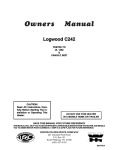
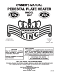
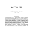
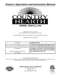
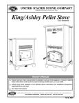
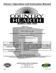
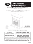
Owners Manual
1864
Hasty Baker Range
CAUTION!
Read All Instructions Carefully Before Starting The Installation or Operating This
Stove.
NOTE: THIS IS NOT A
U.L. LISTED COAL BURNING STOVE
DO NOT USE THIS HEATER
IN A MOBILE HOME OR TRAILER
SAVE THIS MANUAL FOR FUTURE REFERENCE
STATES STO
TED
V
NI
USSC
COMPANY
E
U
THIS MANUAL WILL HELP YOU TO OBTAIN EFFICIENT, DEPENDABLE SERVICE FROM THE HEATER, AND ENABLE
YOU TO ORDER REPAIR PARTS CORRECTLY. KEEP IN A SAFE PLACE FOR FUTURE REFERENCE.
UNITED STATES STOVE COMPANY
227 Industrial Park Road
P.O. Box 151
South Pittsburg, TN 37380
(423) 837-2100
Keeping America Warm
since 1869
851500
Illustrations
21-1/2"
STOVE DIMENSIONS
FIGURE 1.
34-3/4"
30"
FLOOR
PROTECTOR
(SIDE VIEW)
(FRONT VIEW)
28"
17-3/4"
Specifications
Height (Overall)......................................
Width......................................................
Depth......................................................
Firebox Depth.........................................
Flue Size (Round)....................................
Door Opening.........................................
30"
34.75"
21.5"
15"
6"
13" x 10
Material............................................
100% Cast Iron
Fuel....................................................
Coal or Wood
Weight.........................................................
313 lbs.
Instructions for Warming Oven Attachment
1. Align the cast iron warming oven brackets (small end down,
holes to the inside) with the edge of the stove top, ensuring that
the bracket corners are lined up with the corresponding back
corners of the stove top. It is easier to work with one bracket at
a time.
2. Once the bracket is aligned, mark through the holes (one per
bracket) on to the top of the stove using a sharp scribe. You may
have to estimate the center of the hole, but it doesn't have to be
exact.
3. Remove the bracket(s).
4. Locate and mark the center of the hole with a sharp center
61-1/2"
punch to prevent the drill from wandering when drilling.
5. Use a variable speed drill motor with a 1/4" drill bit. Drill the
holes at a LOW SPEED setting, using light pressure, straight
through the stove top.
6. Complete the assembly of the warming oven as follows:
- Fasten the brackets to the stove shop
- Install the warming oven on the brackets
- Install the back splash shield between the stove
and the warming oven. The lip on the splash shield
should be at the bottom facing the front of the stove.
- Install the top piece on the warming oven.
7. Installation should now be completed.
2
29-1/2"
25"
CONGRATULATIONS!
You have purchased the Hasty Baker Range from North America's oldest manufacturer of wood and coal burning
products. Our Hasty Baker Range is an endeared classic that is still used daily in many parts of our country. Our
range is fully functional and its large firebox with shaker grate allows stove to burn both wood and coal. Convenient
ash drawer makes cleaning out ashes easy. An Optional Warming Oven is available. Stove comes pre-assembled
except for legs and base.
Wood is our only Renewable Energy Resource. Please do your part to preserve our wood supply. Plant at least
one tree each year. Future generations will thank you.
Safety Rules
SAFETY NOTICE: If this heater is not properly installed a house, fire may result. For your safety, follow the
installation directions. Contact local building or fire officials about restrictions and installation inspection
requirements in your area.
Read these rules and the instructions carefully.
1.
The installation of this stove must comply with your local building code rulings. Please observe the clearances to
combustibles. (Refer to Figures 1 and 2) Stove must be 36" from a combustible wall (wood or plaster board) at
rear or sides.
2.
DO NOT install this stove in a mobile home or trailer.
3.
Always connect the stove to a chimney and vent to the outside. Never vent to another room or inside a building.
4.
DO NOT connect a wood burning to an aluminum Type B gas vent. This is not safe and prohibited by the NFPA
(National Fire Protection Agency) This stove requires approved masonry or a UL 103 HT Listed Residential Type
and Building Heating Appliance Chimney. Use a 6" diameter chimney or larger, that is high enough to give a good
draft.
5.
Be sure that your chimney is safely constructed and in good repair. Have the chimney inspected by the fire
department or a qualified inspector. Your insurance company may be able to recommend a qualified inspector.
6.
Creosote or soot may build up in the chimney connector and chimney and can cause a house/building fire. Inspect
the chimney connector and chimney twice monthly during the heating season and clean as necessary. (See
Chimney Maintenance, page 6)
7.
Provide air for proper combustion from outside the house into the room where the stove is located. If the intake is
not in the same room, air must have free access to the room.
8.
To prevent injury, do not allow anyone to use this stove who unfamiliar with the correct operation of the stove.
9.
For further information on using your stove safely, obtain a copy of the National Fire Protection Association publication "Using Coal and Wood Stoves Safely" NFPA No. HS-10-1976. The address of the NFPA is Batterymarch Park,
MA, 02269.
10. Dispose of the ashes in a metal container with a tight fitting lid. Keep the closed container on a non-combustible
floor or on the ground, well away from all combustible materials. Keep the ashes in the closed container until all
cinders have thoroughly cooled. The ashes may be buried in the ground or picked up by a refuse collector.
11. The special paints used on this stove may give off some smoke and an odor while they are curing during the first
few fires. Paint discoloration will occur if the stove is overfired.
12. This stove has a painted surface which is durable but it will not stand rough handling or abuse. When installing
your
stove, please handle with care. Clean with soap and warm water when stove is not hot. Do not use any acids or
scouring soap, as the will wear and dull the finish.
13. While the stove is in operation, all persons, young children especially, should be alerted to the hazards from high
surface temperatures and should keep away to avoid burns or clothing ignition. Small children should be carefully
supervised when they are in the same room with the stove.
14. Keep stove area clear and free of all combustible materials such as gasoline and/or other flammable vapors and
liquids
3
Assembly and Installation
1.
MINIMUM CLEARANCE
TO COMBUSTIBLE WALLS
Uncrate and/or unpack the heater, remove
cardboard packaging and protective poly
bag.
2.
Attach (4) legs to rail bases to form a base
which stove will set on
3.
Attach boot assembly to rear of stove using
the enclosed hardware package.
4.
Place stove in desired location.
5.
Place top extension on right hand side of the
stove.
6.
Place lid supports into position on top of
stove.
7.
Place lids into position on top of stove.
18"
39-1/2"
(51-1/2")
(60")
38"
(42")
36"
(48")
44"
(48")
11-1/2"
FLOOR
PROTECTOR
FLOOR
PROTECTOR
10-1/4
FIGURE 1
FIGURE 2
Clearances in () are for Canada ONLY.
HEATER/FLOOR PROTECTOR LOCATION
DASHED LINES
SHOW STRAIGHT
OUT CHIMNEY
CONNECTOR
Place the heater on solid masonry or solid concrete. When
the heater is used on a combustible floor, use an Underwriters Listed floor protector. The floor protector must comply
with UL Standards. The base should extend at least 18"
beyond the door side of the heater and should extend under
the flue pipe if it is elbowed towards a wall. (Fig. 3).
1.
The stove must have its own flue. Do not connect this
unit to a chimney flue serving other appliances.
2.
After observing the clearances to combustibles, locate
your floor protector accordingly and carefully place the
stove in your selected location. Install stove pipe,
elbows and thimble as necessary, utilizing either a
recently cleaned and inspected masonry chimney or a
UL 103 HT Listed Residential Type and Building Heat
ing Appliance Chimney.
3.
If your chimney continues to draft excessively, then use
a Barometric Draft Regulator.
4.
Use three (3) sheet metal screws in each stove pipe and
/or elbow joint to firmly hold the stove pipe together. Use
6" round black/blue stove pipe, not galvanized stove
pipe .
5.
Recheck illustrations Fig. 1 through 6 to be sure you
have the proper clearances shown from the stove and
the connector pipe to combustible surfaces. NOTE: If
a wall is only faced with brick or stone, consider it as a
combustible wall.
6.
DO NOT install this stove in a mobile home or trailer.
7.
If you have too much draft, then install a 6" cast iron
stove pipe damper in the first joint of the stove pipe.
NON- COMBUSTIBLE
CONSTRUCTION IN
ACCORDANCE WITH
NFPA 211
54"
FLOOR
PROTECTOR
36"
36"
36"
FIG. 3
RIGHT
WRONG
WRONG
FIG. 4
CAUTION!
KEEP FURNISHINGS AND OTHER
COMBUSTIBLE MATERIALS
AWAY FROM THE HEATER.
4
38"
Chimney Connection
MASONRY CHIMNEY
The masonry chimney must comply with UL codes. Before using an existing masonry chimney, clean the chimney and inspect
the flue liner to be sure it is safe to use. Make repairs before attaching the heater. See Page 3, Item 5. Look at Fig. 5. The
connector pipe and fittings you will need to connect directly to a masonry chimney are shown. If the connector pipe must
go through a combustible wall before entering the masonry chimney, consult a qualified mason or chimney dealer. The
installation must conform to local fire codes, and NFPA 211. Do not connect this heater into the same chimney flue as the
fireplace or flue from another heater. The chimney used for a heater must not be used to ventilate the cellar or basement.
If there is a cleanout opening at the base of the chimney, close it tightly.
UL LISTED CHIMNEY
Carefully follow chimney manufacturer's instructions. Use only listed type HT per UL 103, 6-in diameter black or blued chimney
connector, minimum 24 gauge steel. If your chimney starts at the ceiling (Fig. 6), you will need enough 6" pipe to reach the ceiling.
The top of the chimney must be at least 3 feet above the roof and be at least 2 feet higher than any point of the roof within 10 feet.
(Fig 6)
FLUE CONNECTION-NON-COMBUSTIBLE WALL
RULES FOR CONNECTOR PIPE INSTALLATION
1.
2.
3.
4.
5.
6.
7.
NON-COMBUSTIBLE WALL
THIMBLE
Crimped end of the pipe must be installed away from the heater.
The pipe must be hand formed to an oval shape which should
slide into the collar top. The pipe should be firmly attached to
the collar top with 3 screws and sealed with furnace cement.
Slope any horizontal pipe upward toward the chimney at least
1/4 " inch for each foot of horizontal run.
You must have at least 18" inches clearance between any
horizontal piping and the ceiling. (Fig. 2)
The pipe cannot extend into the chimney flue.(Fig. 4)
Seal each connector pipe joint with furnace cement. Also seal
the pipe at the chimney.
Use 3 sheet metal screws at each joint to make the piping rigid.
It is recommended that no more than two (2) 90 degree bends
be used in the stove pipe installation as more than two (2) may
decrease the amount of draw and possibly cause smoke
spillage.
NOTE: The chimney connector shall not pass through an
attic, roof space, floor, ceiling, or similar concealed space.
Where passage through a wall or partition of combustible
construction is desired, the installation must conform with
NFPA 211.
COLLAR
PIPE
ELBOW
BAROMETRIC
DRAFT REGULATOR
PIPE
FIG. 5
FLOOR PROTECTOR
CHIMNEY CAP MANDATORY
Operation of the Stove
1.
Burn wood or coal only. The wood should be air dried
(seasoned) for at least 6 months after cutting. Build six (6)
small fires upon initial firing. Light wood or coal using paper,
twigs, etc.
2. After the fire has been started and is burning satisfactorily,
adjust the rate of burning by opening or closing the draft control
on side of part.
3. Never build extremely large fires in this type stove as damage
to the stove or smoking may result.
4. If you have too much draft, then regulate the draft with a 6" cast
iron stove pipe damper properly installed in the first joint of the
stove pipe.
4. DO NOT touch the stove after firing
7. Never overfire this stove by building excessively hot fires as a
house/building fire may result.
8. Inspect stove pipe every 90 days. Replace immediately if
stove pipe is rusting or leaking smoke into the room.
9. This is a cast iron stove. It does not have welded seams. From
time to time you may have to "tune-up" the stove by refilling
and/or replacing the stove cement or mortar along the seams.
10. If stove begins to glow or turn red, you are overfiring.
3 FT. MIN.
2 FT. MIN
10 FT.
PIPE REDUCER
NON-COMBUSTIBLE
CONSTRUCTIONIN
ACCORDANCEWITH
NFPA211
11 FT. MINIMUM
BAROMETRIC
DRAFT REGULATOR
PIPE
FIG. 6
FLOOR PROTECTOR
5
WARNING!
NEVER STORE FLAMMABLE LIQUIDS,
ESPECIALLY GASOLINE. IN THE
VICINITY OF THE HEATER.
CAUTION!
NEVER USE GASOLINE, GASOLINE-TYPE
LANTERN FUEL, KEROSENE, CHARCOAL
LIGHTER FLUID, OR FLAMMABLE
LIQUIDS TO START OR "FRESHEN UP" A
FIRE IN THE HEATER.
CAUTION!
OVERFIRING THE APPLIANCE MAY
CAUSE A HOUSE FIRE. IF A UNIT OR
CHIMNEY CONNECTOR GLOWS, YOU
ARE OVERFIRING.
CAUTION!
USE WOOD OR COAL. DO NOT USE
DRIED LUMBER, TREATED WOOD
ARTIFICIAL OR PRESSED LOGS.
WARNING!
NEVER OPERATE THIS HEATER WITH THE
FUEL DOOR OPEN.
WARNING!
DO NOT OBSTRUCT THE SPACE BENEATH
THE HEATER
Service Hints
5.
Do not expect a heater to draw. It is the chimney that creates
the draft. Smoke spillage into the house or excessive buildup
of water or creosote in the chimney are warnings that the
chimney is not functioning properly. Correct problem before
using heater. Possible causes are:
1.
The connector pipe may push into the chimney too far,
stopping the draft. (Fig. 4)
2.
If the chimney is operating too cool, water will condense
in the chimney and run back into the stove. Creosote
formation will be rapid and may block the chimney.
Operate the heater at a high enough fire to keep the
chimney warm preventing this condensation.
If the fire burns well but sometimes smokes or burns
slowly, it may be caused by the chimney top being lower
than another part of the house or a nearby tree. The wind
blowing over a house or tree, falls on top of the chimney
like water over a dam, beating down the smoke. The top
of the chimney should be at least 3 feet above the roof
and be at least to 2 feet higher than any point of the roof
within 10 feet (Fig. 6).
Chimney Maintenance
Creosote - Formation and Need for Removal
If creosote has accumulated, it should be removed. Failure to
remove creosote may cause a house fire. Creosote may be
removed by using a chimney brush or other commonly
available materials.
When wood is burned slowly, it produces tar and other
organic vapors, which combine with expelled moisture to
form creosote. The creosote vapors condense in the relatively cool chimney flue of a slow burning fire. As a result,
creosote residue accumulates on the flue lining. When ignited this creosote makes an extremely hot fire.
Chimney fires burn very hot. If the chimney connector should
glow red, immediately call the fire department, then reduce
the fire by closing the inlet air control and pour a large quantity
of coarse salt, baking soda or cool ashes on top of the fire in
the firebox. CAUTION: A chimney fire may cause ignition of
wall studs or rafters which you thought were a safe distance
from the chimney. If you have a chimney fire, have your
chimney inspected by a qualified person before using again.
The chimney connector and chimney should be inspected at
least twice monthly during the heating season to determine
if a creosote buildup has occurred.
CAUTION! Do not touch the heater until it has cooled.
NOTE:
FOR YOUR SAFETY, WE RECOMMEND INSTALLING SMOKE DETECTORS IN YOUR HOME IF NOT
ALREADY INSTALLED.
6
PARTS LIST AND DIAGRAM - 1864
1
2
3
4
5
6
7
8
9
10
11
12
13
14
15
16
17
18
19
20
21
22
23
24
25
38
37
36
48
47
46
45
44
43
42
41
40
39
35
34
33
32
31
30
29
28
27
26
KEY
1
2
3
4
5
6
7
8
9
10
11
12
13
14
15
16
17
18
19
20
21
22
23
24
25
26
27
28
29
30
31
32
33
34
35
36
37
38
39
40
41
42
43
44
45
46
47
48
PART NO.
89998
89999
891000
891001
891002
891003
891004
891005
891006
891007
891008
891009
891010
891011
891012
891013
891014
891015
891016
891017
891018
891019
891020
891021
891022
891023
891024
891025
891026
891027
891028
891029
891030
891031
891032
891033
891034
891035
891036
891037
891038
891039
891040
891041
891042
891043
891044
891045
DESCRIPTION
QTY.
1/4 Lid Support
2
8" Cook Lid
4
Lid Support
2
Connecting Rod
1
Damper Lever
1
Damper
1
Rear Flue Boot
1
Front Flue Boot
1
Fuel Cover
1
Stove Back
1
Right Side Grate
1
Draft Control Knob
1
Draft Frame
1
Rear Draft Control
1
Oven Left Side
1
Side Draft Control
1
Stove Left Side
1
Ash Pan Guide
2
Left Side Liner
1
Stove Bottom
1
Side Apron
2
Leg
4
Front/Rear Apron
2
Master Handle
1
Ash Pan
1
Feed Door
1
Ash Door
1
Door Latch
2
Door Handle
2
Oven Door
1
Oven Door Handle
1
Spring Cover
1
Door Spring
1
Oven Rack
1
Front Grate Support
1
Stove Front
1
Oven Bottom
1
Oven Right Side
1
Shaker Grate
1
Ash Funnel
2
Rear Grate Support
1
Stove Right Side
1
Oven Top
1
Center Lid Support
1
Oven Back
1
Stove Top Extension 1
Stove Top
1
5-1/2" Cook Lid
2
7
HOW TO ORDER REPAIR PARTS
THIS MANUAL WILL HELP YOU OBTAIN EFFICIENT, DEPENDABLE SERVICE FROM
THE HEATER, AND ENABLE YOU TO ORDER REPAIR PARTS CORRECTLY.
KEEP IN A SAFE PLACE FOR FUTURE REFERENCE.
WHEN WRITING, ALWAYS GIVE THE FULL MODEL NUMBER WHICH IS ON THE
NAMEPLATE ATTACHED TO THE BACK OF THE HEATER.
WHEN ORDERING REPAIR PARTS, ALWAYS GIVE THE
FOLLOWING INFORMATION AS SHOWN IN THIS LIST:
1. The PART NUMBER
2. The PART DESCRIPTION
3. The MODEL NUMBER: 1864
4. The SERIAL NUMBER:
UNITED STATES STOVE COMPANY
227 Industrial Park Road
P.O. Box 151
South Pittsburg, TN 37380
(423) 837-2100
www.USSTOVE.com