1
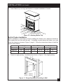
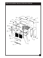
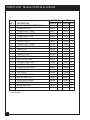
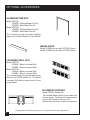
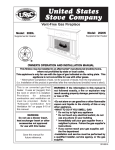
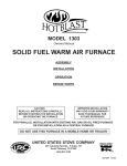
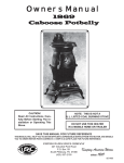
U
STATESSTOVE
TED
NI
USSC
COMPANY
United States
Stove Company
Vent-Free Zero-Clearance Universal Firebox
Model VFZC36 and Model VFZC42
Certified for use with any Unvented Log Set tested to ANSI Z21.11.2
This Firebox may also be installed in manufactured (mobile) homes,
where not prohibited by state or local codes.
Shown with optional
cabinet mantel, hearth
base, brass trim, louvered
grills, and firebrick panels.
OWNER'S OPERATION AND INSTALLATION MANUAL
FOR USE ONLY
WITH DECORATIVE TYPE
UNVENTED ROOM HEATERS
Carefully review the instructions supplied
with the decorative type unvented room heater
for the minimum fireplace size requirement.
DO NOT BUILD A WOOD FIRE
DO NOT INSTALL THE APPLIANCE IN
THIS FIREBOX, UNLESS THIS FIREBOX
MEETS THE MINIMUM DIMENSIONS REQUIRED
FOR THE INSTALLATION.
Save this manual for future
reference.
WARNING: If the information in this manual is not followed exactly, a fire or
explosion may result causing property damage, personal injury or loss of life.
851298 2/98
TABLE OF CONTENTS
SECTION
PAGE
PRODUCT FEATURES...........................................................................................2
LOCAL CODES........................................................................................................2
WARNINGS/SAFETY INFORMATION......................................................................3
VFZC36 SPECIFICATIONS.....................................................................................4
VFZC42 SPECIFICATIONS.....................................................................................5
LOCATING THE FIREBOX.....................................................................................6
AIR FOR COMBUSTION AND VENTILATION........................................................6
INSTALLATION..................................................................................................6-14
PARTS DIAGRAM ................................................................................................15
PARTS LIST...........................................................................................................16
OPTIONAL ACCESSORIES............................................................................17-18
HOW TO ORDER REPAIR PARTS........................................................................19
PRODUCT FEATURES
Operation
These fireboxes are approved for installation with any certified vent-free gas log heater up to
40,000 BTU's. They require no outside venting or chimney making installation easy and inexpensive. When used without the optional blower (model VFZCB), the firebox requires no
electricity making it ideal for emergency backup heat.
LOCAL CODES
Installation must conform with local codes or, in the absence of local codes, with the National
Fuel Gas Code, ANSI Z223.1. When using the optional Blower Kit, this firebox must be
electrically grounded in accordance with local codes or, in the absence of local codes, with
the National Electrical Code, ANSI/NFPA 70.
*Available from:
American National Standards Institute, Inc.
1430 Broadway
New York, NY 10018
2
National Fire Protection Association, Inc.
Batterymarch Park
Quincy, MA 02269
WARNINGS/SAFETY INFORMATION
IMPORTANT: Read this owner's manual carefully and completely before trying to
assemble, operate, or service this firebox. Improper use of this firebox can cause
serious injury or death from burns, fire, explosion, electrical shock, and carbon
poisoning.
WARNING: Any change to this firebox or its controls can be dangerous.
1. This firebox shall not be installed in a bedroom or bathroom.
2. Never install the firebox
* in a recreational vehicle
* where curtains, furniture, clothing, or other flammable objects are less than
36 inches from the front, top, or side of the firebox
* in high traffic areas
* in windy or drafty areas
3. Do not use this firebox as a wood-burning fireplace.
Use only "Vent-Free Gas Log Heaters".
4. Do not add extra logs or ornaments such as pine cones, vermiculite, or rock wool.
Using these added items can cause sooting.
5. You must operate this firebox with the fireplace screen, hood, and brick liner
in place. Make sure these parts are in place before running firebox.
6. Do not allow fans to blow directly into the firebox. Avoid any drafts that alter burner flame
patterns. Ceiling fans can create drafts that alter burner flame patterns. Altered burner
patterns can cause sooting.
7. Do not use a blower insert, heat exchanger insert or other accessory not approved
for use with this heater.
8. Vent-free gas log heater installed in this firebox requires fresh air ventilation to run
properly. See Air for Combustion and Ventilation instructions in Gas Log Heater owner's
manual.
9. Do not run firebox
* where flammable liquids or vapors are used or stored
* under dusty conditions
10. Do not use this firebox to cook food or burn paper or other objects.
11. Never place any objects in the firebox or on logs.
12. Firebox front and screen becomes very hot when running firebox. Keep children and
adults away from hot surfaces to avoid burns or clothing ignition. Firebox will remain
hot for a time after shut-down. Allow surfaces to cool before touching.
13. Carefully supervise young children when they are in the room with firebox.
14. Turn firebox off and let cool before servicing. Only a qualified service person should
service and repair firebox.
15. Operating vent-free gas log heaters in a firebox above elevations of 4,500 feet could
cause pilot outage.
3
VFZC36 SPECIFICATIONS
INSIDE FIREBOX
FIREBOX TOP VIEW
NAILING FLANGE
FIREBOX FRONT VIEW
4
ELECTRICAL
ACCESS
GAS LINE
ACCESS
FIREBOX SIDE VIEW
VFZC42 SPECIFICATIONS
INSIDE FIREBOX
FIREBOX TOP VIEW
NAILING FLANGE
FIREBOX FRONT VIEW
ELECTRICAL
ACCESS
GAS LINE
ACCESS
FIREBOX SIDE VIEW
5
LOCATING FIREBOX
Planning
Plan where you will install the firebox. This will save time and money later when you install
the firebox. Before installation, consider the following:
1. Where the firebox will be located. Allow for wall and ceiling clearances (see
Installation Clearances, page 7).
2. If installing firebox directly on carpeting, tile or other combustible material, other than
wood flooring, the firebox must be installed on a metal or wood panel extending the full
width and depth of the enclosure.
3. Everything needed to complete installation.
4. These models CANNOT be installed in a bedroom or bathroom.
5. Proper air for combustion and ventilation (see below).
AIR FOR COMBUSTION AND VENTILATION
Provisions for adequate combustion and ventilation air must be made before
installation of this unit. Please Refer to manual accompanying log set.
INSTALLATION
NOTICE
A qualified service person must install firebox. Follow all local codes.
WARNING
Never
*
*
*
install the firebox
in a bedroom or bathroom
in a recreational vehicle
where curtains, furniture, clothing, or other flammable objects
are less than 36 inches from the front, top, or sides of the firebox
* in high traffic areas
* in windy or draft areas
CAUTION
Vent-Free Gas Log heaters installed in this firebox create warm air currents. These
currents move heat to wall surfaces next to firebox. Installing firebox next to vinyl
or cloth wall coverings or operating firebox where impurities in the air (such as
tobacco smoke) exist, may discolor walls.
IMPORTANT: Make sure the firebox is level. If firebox is not level, log set will not work
properly.
6
INSTALLATION CONTINUED
IMPORTANT: Vent-free gas log heaters add moisture to the air. Although this is beneficial,
installing firebox in rooms without enough ventilation air may cause mildew to form from too
much moisture. (See Air for Combustion and Ventilation, in your Vent-Free gas log heater's
owners manual.)
INSTALLATION CLEARANCES
WARNING
Maintain the minimum clearances. If you can, provide greater clearances from
floor, ceiling, and adjoining wall.
Carefully follow the instructions below. This will ensure safe installation.
Minimum Wall and Ceiling Clearances (see Figure 1, below)
A. Clearances from the side of the firebox opening to any combustible wall should not
be less than 6 inches. (This applies to built-in installation or using an "optional" cabinet
mantel kit.)
B. Clearances from the top of the firebox opening to the ceiling should not be less than
42 inches.
Mantel Clearances for Conventional Installation
NOTE: CLEARANCES ARE THE
SAME IF USING OPTIONAL
CABINET MANTELS OR BUILT-IN
INSTALLATION.
42"
6" TO
SIDE WALL
Figure 1 - Minimum Clearance to Wall and Ceiling
7
INSTALLATION CONTINUED
Mantel Clearances for Built-in Installation
If placing custom mantel above built-in firebox, you must meet minimum clearance between
WALL
mantel shelf and top of firebox opening.
MANTEL SHELF
UNDERSIDE OF
MANTEL SHELF
Figure 2 - Minimum Mantel
Clearances for Built-in Installation
MANTEL
WIDTH
DISTANCE TO
UNDERSIDE OF
MANTEL
TOP OF
FIREPLACE
OPENING
If your installation does not meet the
above minimum clearances, you must:
* raise the mantel to an
acceptable height, OR
* remove the mantel.
ALL MINIMUM
DISTANCES ARE
IN INCHES
SIDE VIEW OF FIREBOX
Installing the Fireplace Screen.
1.
2.
3.
Insert each rod through the rings located at the top of the screen. NOTE: Before placing
the last ring over the rod, slide the tinnerman clip (included in the parts bag) onto the rod
and then slide the last ring over the rod. (See Figure 3)
Insert the right screen and rod into the hole in the side trim and line up rod with the back
hole in the firebox top and fasten with one of the 5/16" head screws included.
Now insert the left screen and rod as above. (Figure 3)
HOLE FOR ROD
TINNERMAN
CLIP
SCREW
ROD
RING
SCREEN
8
Figure 3 - Installing Fireplace Screen
INSTALLATION CONTINUED
Installing the Fireplace Hood.
1.
Slide the Hood over the shoulder screws and gentle press down until secure. NOTE:
There are (2) shoulder screws on each side of the firebox opening directly below the
top plate. These shoulder screws should line up with the notches on the sides of the
Fireplace Hood. (See Figure 4)
SHOULDER SCREW
IMPORTANT:
The Firebox Hood must not
be replaced with a hood/
canopy which may be
provided with the decorative
type unvented room heater.
HOOD CUT-AWAY
TO SHOW
UNDERSIDE
Figure 4 - Installing the Fireplace Hood.
Installing the Firebrick Panels into the firebox.
1.
2.
3.
4.
5.
6.
Before installing the firebrick panels you must first remove the brick brackets.
A 5/16" nut driver will be required. (See Figure 5a & b, below for location)
Carefully remove the firebrick panels from their box.
Decide which side of the firebox you want the gas line to enter and knock out the
appropriate holes in the cabinet, firebox, and the firebrick panel.
Place the back firebrick panel in the firebox, as shown in Figure 5a.
Place the side firebrick panels in the firebox, as shown in Figure 5b.
You can now replace the brick brackets using a 5/16" nut driver.
BRICK BRACKET
ATTACH BRACKET W/SCREW
BACK FIREBRICK PANEL
(OPTIONAL) SIDE KNOCK-OUT
HOLE FOR GAS LINE
(OPTIONAL) KNOCK-OUT HOLE
IN FIREBRICK FOR GAS LINE
SIDE FIREBRICK PANEL
Figure 5a
Figure 5b
Firebox shown with some parts missing for clarity.
9
INSTALLATION CONTINUED
Installing the Optional VFZCB Blower Kit.
You may install the VFZCB Blower Kit in the VFZC36 and the VFZC42 Fireboxes. (NOTE:
When installing the Blower kit you must also use one of the optional Louvered Grill
Kits*.)
Each Blower Kit includes the following:
1- 120 CFM Blower
1- Manual fan control switch
1- Parts bag
1- Installation Instruction sheet
*The Louvered grill kits (see Optional Accessories), along with the Blower, will aid in the
distribution and circulation of the heat throughout the heating area. NOTE: Install blower
assembly per instruction sheet included in Blower Kit.
IMPORTANT: The blower, when installed, must be electrically grounded in accordance with
local codes or, in the absence of local codes, with the National Electrical Code, ANSI/NFPA70.
BLOWER
NOTE: If any of the original wire must
be replaced, it must be replaced with
600 volt, 150 C. wire or its equivalent.
BLACK
BLACK
Wiring Diagram For Optional
VFZCB Blower Kit
BLACK
WHITE
BLACK
WHITE
10
GREEN
BLACK
WHITE
RHEOSTAT
2X4 JUNCTION BOX
& JUNCTION BOX
COVER
TO
POWER
SUPPLY
INSTALLATION CONTINUED
Firebox Installation Using Optional Mantel.
This firebox may be installed using the cabinet mantel with hearth base accessory against a
wall in your home. You must use one of the Satin Black or Polished Brass Trim Kits available
when installing your firebox with the optional mantel kit. (See Accessories on page 17 & 18).
NOTE: The Trim Kits provide a finished appearance covering rough and/or unfinished mantel
edges.
NOTE: The instructions below show installation using the VFZC series cabinet mantels and
hearth base accessories. The hearth base accessory shown is optional for this installation.
You can install the firebox and mantel directly on the floor. The VFZC series face mantel
accessories cannot be installed with the hearth base accessory. You must install the face
mantels directly on the floor. (See Optional Accessories, page 17)
NOTE: If installing directly on carpeting, tile or other combustible material, other than
wood flooring, the firebox must be installed on a metal or wood panel extending the full
width and depth of the enclosure.
NOTE: If using the VFZC series face mantel accessory, a wall recess opening will be needed.
See installation instructions for VFUN36FM/VFUN42FM Face Mantel accessory.
1. Assemble cabinet mantel, hearth base (optional), and trim accessories.
Assembly instructions are included with each accessory.
2. If using an optional VFZCB blower, install a properly grounded, 120 volt three-prong
electrical outlet at firebox location if an outlet is not there. If possible, locate outlet so
cabinet mantel will cover it when installed (see Figure 6, below).
3. Install gas piping to firebox location. For this installation you will need an approved
flexible gas line (if allowed by local codes) and a manual shutoff valve. The flexible gas
line must be the last item installed on the gas piping. See Connecting to Gas Supply
in your log set owner's manual.
NOTICE
A qualified service person must connect firebox to gas supply. Follow all local
codes.
4.
Place (optional) hearth base accessory against wall at installation location. Cut an
access hole in hearth top to run flexible gas line to firebox (see Figure 6). Make sure to
locate access hole so cabinet mantel will cover it when installed. NOTE: you can secure
base to floor using wood screws. Countersink screw heads and putty over.
Flexible Gas Line
Hearth Base
Electrical Outlet
Gas Line
Access Hole
Figure 6 - Placing (optional) Hearth Base against wall
11
INSTALLATION CONTINUED
5.
Center the unit on the Hearth Base. Run the Gas Line into the firebox. You can access
the firebox from the left, right, or rear of the unit by knocking out the plugs in the cabinet
and inside the firebox. NOTE: You must also knock out the hole in the Firebrick Panel.
6.
If installing Optional VFZCB
Blower Kit, use a standard
3-prong power supply cord
(not included) and plug
blower into outlet.
NOTE: See Blower
Kit Instruction sheet
for full installation
instructions.
Knock out plug in
cabinet and firebox
and run Flexible Gas
Line into firebox.
3-Prong power
supply cord
(not included)
Figure 8 - Installing Firebox on Hearth Base
7.
8.
Place the Cabinet Mantel Legs on Hearth Base and slide each side firmly up against
the unit (See Figure 9). NOTE: The Cabinet Mantel Legs and Hearth Base should be
against the wall.
Lower the header into the slots at
Header
the top of each leg, using four
1-1/4" screws to attach header
to the legs.
Wood
Screws
Right
Leg
Figure 9 - Installing Cabinet Mantel Legs & Header
12
INSTALLATION CONTINUED
9.
Lower Mantel top onto legs and header to complete installation of mantel.
Figure 10 - Installing Mantel Top
Built-in Firebox Installation.
Built-in installation of this firebox involves installing the firebox into a framed-in enclosure.
This makes the front flush with the wall. If installing a mantel above the firebox, you must
follow the clearances shown in Figure 2, page 8. Follow the instructions below to install the
firebox in this manner.
Height
Model #
VFZC36
VFZC42
1.
Actual
35"
35"
Front Width
Framing
35-1/4"
35-1/4"
Actual
39-3/8"
45-3/8"
Framing
39-1/2"
45-1/2"
Depth
Actual
20-3/8"
20-3/8"
Framing
21"
21"
Frame in rough opening. Use dimensions shown in Figure 11 for rough opening.
21"
35-1/4"
39-1/2" - VFZC36
45-1/2" - VFZC42
Figure 11 - Rough Opening for Installing in Wall
13
INSTALLATION CONTINUED
If installing in a corner, use the dimensions shown in Figure 12 below for the rough
opening. The height is 35", which is the same as the wall opening in Figure 11,
page 13.
53-3/4" (VFZC36)
58" (VFZC42)
38" (VFZC36)
41" (VFZC42)
39-1/2" (VFZC36)
45-1/2" (VFZC42)
76" (VFZC36)
82" (VFZC42)
2.
3.
4.
5.
6.
7.
8.
9.
Figure 12 - Rough Opening for Installing in Corner.
Install gas piping to firebox location. NOTE: This unit give (3) options on where the gas
line can be ran into the firebox. Knock outs are provided on the left and right side of the
firebox and also the back of the firebox, for gas line connection. See Connecting to Gas
Supply in your Log Set Owner's Manual.
Carefully set the firebox in front of rough opening with back of firebox inside wall opening.
If using the VFZCB (optional) Blower Kit, see installation instructions included with blower.
Attach flexible gas line to log set. See Connecting to Gas Supply in log set owner's
manual.
Carefully insert firebox into rough opening.
Attach firebox to wall studs using nails or wood screws through holes in nailing flange
(see Figure 13).
Check all gas connections for leaks. See Checking Gas Connections in log set owner's
manual.
If using optional Trim Kit, install the trim after final finishing and/or painting of wall. See
instructions included with Trim Kit for attaching trim. (See Optional Accessories, page
18, for the different kits available).
Figure 13 - Attaching Firebox to
Wall Studs
14
Nailing Flanges Holes
(2 on each side of firebox)
PARTS DIAGRAM Models VFZC36 & VFZC42
15
PARTS LIST Models VFZC36 & VFZC42
KEY
1
2
3
4
5
6
7
8
9
10
*
11
12
13
14
15
16
17
18
*
19
*
20
DESCRIPTION
CABINET BOTTOM ASSEMBLY
FIREBOX BACK
FIREBOX LEFT SIDE
FIREBOX RIGHT SIDE
FIREBOX BOTTOM
FIREBOX TOP
CABINET BACK
CABINET LEFT SIDE
CABINET RIGHT SIDE
INNER TOP
INSULATION
CABINET TOP
LEFT SIDE TRIM
RIGHT SIDE TRIM
TOP/BOTTOM TRIM
CURTAIN ROD
FIREPLACE SCREEN
LOWER PLATE
TOP PLATE
SHOULDER SCREW
BRICK PANEL SET
BACK BRICK PANEL
SIDE BRICK PANEL
BRICK BRACKET
HOOD
* = Not Shown
16
VFZC36
PART# QTY.
69141
1
24616
1
24617
1
24618
1
24619
1
24620
1
24621
1
24622
1
24623
1
24624
1
24649
1
24625
1
24626
1
24627
1
24628
2
24677
2
89897
2
24645
1
24646
1
83477
12
89883
1
89884
1
89885
2
24650
3
24631
1
VFZC42
PART# QTY.
69142 1
24635 1
24617 1
24618 1
24638 1
24639 1
24640 1
24622 1
24623 1
24644 1
24672 1
24636 1
24626 1
24627 1
24637 2
24678 2
89898 2
24647 1
24648 1
83477 12
89887 1
89893 1
89885 2
24650 3
24643 1
OPTIONAL ACCESSORIES
You may purchase these firebox accessories from your local dealer. If they can not supply
these accessories, call United States Stove Company's Sales Department at 1-423-8372100 for information. You can also write to the address listed on the back page of this
manual.
CABINET MANTEL
Two versions are available:
Golden Oak Stained Mantel Model VFGO36M for use with VFZC36
Model VFGO42M for use with VFZC42
Unfinished Mantel Model VFUF36M for use with VFZC36
Model VFUF42M for use with VFZC42
Dimensions (WxHxD):
Model VFGO36M/VFUF36M = 52-1/16" x 48" x 25-3/16"
Model VFGO42M/VFUF42M = 58-1/16" x 48" x 25-3/16"
HEARTH BASE
Golden Oak Stained Hearth Base Model VFGO36B for use with VFGO36M
Model VFGO42B for use with VFGO42M
Unfinished Hearth Base Model VFUF36B for use with VFUF36M
Model VFUF42B for use with VFUF42M
Dimensions (WxHxD):
Model VFGO36B/VFUF36B = 58-3/4" x 5" x 25-3/16"
Model VFGO42B/VFUF42B =64-3/4" x 5" x 25-3/16"
FACE MANTEL
(The Face Mantel is only available unfinished)
Model VFUN36FM for use with VFZC36
Model VFUN42FM for use with VFZC42
Designed for use with recessed
applications.
Drawings are for illustration purposes only. Actual product may very in appearance.
17
OPTIONAL ACCESSORIES
ALUMINUM TRIM KITS
Model VFZC36:
VF36PB - Polished Brass Trim Kit
VF36SB - Satin Black Trim Kit
Model VFZC42:
VF42PB - Polished Brass Trim Kit
VF42SB - Satin Black Trim Kit
The Trim Kits must be used when installing
firebox with Cabinet Mantel or Face Mantel.
BRASS HOOD
Model VF36BH for use with VFZC36 Firebox.
Model VF42BH for use with VFZC42 Firebox.
LOUVERED GRILL KITS
Model VFZC36:
VF36LK - Black Louvered Grills
VF36BL - Brass Louvered Grills
Model VFZC42:
VF42LK - Black Louvered Grills
VF42BL - Brass Louvered Grills
The Louvered grills are required when using
the optional VFZCB blower kit. The Brass
Louvered Grills add an extra touch of class
to the firebox.
BLOWER ACCESSORY
Model VFZCB - Blower Kit
The variable blower allows you to select the
desired speed. The blower circulates heated
air from the fireplace into the room.
(Blower not to scale for illustration purposes)
Drawings are for illustration purposes only. Actual product may very in appearance.
18
HOW TO ORDER REPAIR PARTS
This Manual will help you obtain efficient, dependable service from your Vent-Free
Zero-Clearance Firebox, and enable you to order repair parts.
Keep this manual in a safe place for future reference.
When writing, always give the full model number which is on the nameplate
attached to the firebox.
When ordering repair parts or options, always give the following information as
shown in this list:
1.
2.
3.
4.
The PART NUMBER
The PART DESCRIPTION
The MODEL NUMBER:
VFZC36
VFZC42
The SERIAL NUMBER _____________________
Before installing this firebox, fill in the serial number in the space provided for your
records.
UNITED STATES STOVE COMPANY
227 INDUSTRIAL PARK ROAD
P.O.BOX 151
SOUTH PITTSBURGH, TN 37380
(423) 837-2100
19
U
ATESSTOV
T
S
D
E
TE
I
N
USSC
COMPANY
Keeping America Warm Since 1869
VFZC36/VFZC42
Owner's Manual
Save this manual for future reference.
United States Stove Company
20
227 Industrial Park Road
P.O.Box 151
South Pittsburg, TN 37380
(423) 837-2100