1
r
,
~-..
.--
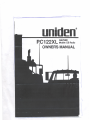
P.C122XL
---
,
1-
~~~~:~B Radio
OWNER1SMANUAL
\
--~
WELCOME
To the world of sophisticated. nii~processor controlled AMlSSB radio communications,
Your UnidenPC122XL represents one of the most advanced mobile type radio ever
designed for use in the Citizens Band Radio Service. It willoperate on any of the 40 AM
frequencies an",Upper and Lower Side Band Frequencies designated by the Department
of Transport and Communications (DOTAC). Your PC 122XL features a frequency
synthesizing circuit with PHASE LOCK LOQf te~niq\J,es, to assure precise freqlJeQCY
control. This radio has been type accepted an;dcel1ified~y thg'DOTAC.
'
;i
".,
.".
'.,
~
.....
i
WARNING
.,',
:j
"
,
,
';,.
" ,
Before transmitting with your trapsmitter. you must obtain a Department ofTransport and/" If
Communicati()rJ:sCitizens Band:Radio Service (CBRS) License. Obtain a brochure and
a CaRS Ucense Application form in your nearest DOTAC office. Mail the completed
application form and the appropriate fee to the Superintendent Regulatory of Ucensing
in the State of Territory in which the station will be operated.
MOBILE INSTALLATION
Plan the location of the radio and microphone bracket before starting installation.
Select a location that is convenient for operation and does not interfere with the
driver or passenger in the vehicle. The radio should be securely fastened to a solid
surface using the mounting bracket and self-tapping screws which are provided.
MOBI LE ANTENNA
Since the maximum allowable power output of the transceiver is limited by the DOT AC.
the antenna is a very important factor affecting transmission distance. It is for this reason
that we strongly recommend that you install only a quality antenna in YOtn'new ca radio
system. You have purchased a superior quality transceiver. Don't diminish its performance by installing an inferior antenna.
h,
,
gnl¥~ Pfc:>perly,matct1ed antenna systemwillallow maxi my'" power transfer from the' 50-;:<'}~~)'i.;1\~t{
.ovmfJ"ansmission line tothe radiating element. Wereconimend
that you use an SWR
','~<:'t~<
metQr when ,installing your antenna. Set your PC122XL to channel 20 and adjust to SWR' ,. >':
";"1..YourlJ.NIDEN dealer is qu~lified.to assist you in theseJection of the proper antenna'
'
to m~etyour' application requirements.
.
.
For automobileinstallation, the whip antenna may be used with good effect. The most
efficient and practical installation is a full quarter wave whip antenna mounted on the
rear deck or fender top, midway between the rear window and bumper.
A short "Ioaded" whip antenna is more convenient to install on your automobile,
although the efficiency is less than a fun quarter wave whip antenna.
For marine installation, consult your dealer for information regardingan adequate
grounding system and ..prevention of electrolysis between fittings on the hull and
water.
:~
So
-1-
..
,.
...,
=
-=
....
.- CONNECTING THE POWER CORDS
With regard to the connection of the power cords, it may be possible or desirable to
connect the red lead (for negative ground systems) or the black lead (for positive
ground systems) to the ignition switch accessory terminal so that the radio is automatically turned off when the ignition switch (key) is turned off.
i'"'" ~Iternately, the power lead may be 'connected to an available terminal on the fuse
,;~:
"';
;
block or even to a point i" ~heV\(irin~
harness.Caremust be taken, how~ver,to guard
{~':~'I"'!against a short circuit condition. When in doubt, please contact your vehicle dealer for
specificinformation for your'vehide. .~
t..,. -'."I
J
'.
.
GROUND INFORMATlpN
,.A negative gro,undsystem is -generallyidentified by the"
- " battery tEirnirnal';being
connected to the vehide motor block, but if you cannot determine the polarity of
your vehide, consult your vehide dealer for information.
NOTE: This radio may be installed and used in any 12-volt DC negative or positive
ground system.
.~
NEGATIVE GROUND SYSTEM
If you are operating on a negative ground system, connect the. red DC power cord
from the radio to the positive "+" battery terminal or other convenient point and
connect the black power lead to the chassis or vehide frame, or the negative" - "
terminal of the battery.
POSITIVE GROUND SYSTEM
If you are operating on a positive ground system, connect the black DC power cord
from the radio to the negative" - " battery terminal or other convenient point and
connect the red power lead to the chassis or vehide frame, or the positive" + "
term inal of the battery.
".:'.
~'"
..
.
-2,-
-=--
.
.
:::::::::::=-~-
, II
--~
-~------
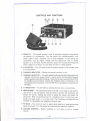
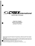
CONTROLS AND FUNCTIONS
@
@
<ID
CID
G)(j)@
@
1. SQUELCH - The squelch control is used to eliminate background noise during
the absence of a transmission. Turn the control fully counterclockwise, then
slowly rotate it back clockwise until all noise disappears. At this setting any
transmission must be slightly stronger than the background noise to "Break
Squelch" or to be heard. Further clockwise rotation will increase the threshold at
which a signal will be heard. You can select any level to "Break Squelch".
2. S/RF METER - This LED meter shows the relative strength of the received signal
or transmit power.
3. CHANNEL INDICATOR
- Displays the channel currently in use.
4. CHANNEL SELECTOR - This switch selects the desired channel for transmission and
reception. All channels, except channel 9 , may be used for communications between
stations operating under different license. Channel 9 has been reserved by the DOTAC
for emergency communications involving the immediate safety of individuals or the
immediate protection of property. This is the DOTAC rule and applies to all operators of
CB radios.
j
I
5. TX INDICATOR - An LED lights to indicatewhen the radio is transmitting.
0'1
6. MICROPHONE- The operational mode of the CB is controlled by the push-totalk switch on the microphone. Pressthe switch to activate the transmitter and
disable the receiver. Releasethe switch to enable the receiver and disable the
transmitter. When transmitting, hold the microphone about 2 inches from your
mouth and speak clearly in a normal voice. The microphone included with the
PC122XLis a detachable,Iow impedance,dynamic type.
7. RF GAIN - This control is usedto adjust signalreception in areaswhere strong
signalsarepresent.Turn the control fully clockwisefor maximum reception.
8. VOLUME CONTROL - Rotate cloc,kwise to turn radio on and to increase
volume.
..
-3'-
~
~
---
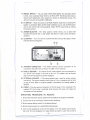
9. NB/ANL SWITCH - You can select either Noise Blanker and Automatic Noise
Limiter, only Automatic Noise limiter or all filters OFF. The NB and ANL help to
reduce harsh background noise caused by a variety of interference sources. The
ANL will not work in the USB orLSB mode.
10. PA SWITCH- Move this switch to the Public Address mode when an external PA
speaker is connected. When tb~ ~A mode is s~lected, you can use tt)e PA function
and yetcan monitor CB incoming signals. Adjust the PA outPLlt level by rotating
the volume control.
,
..
,'.,'
J1.~ AM/SSB SELECTOR - The ,thr,i!e position' switch allows you to select AM
:",
(standard40 channel CB) or USB (Upper Side Band) or LSB (Lower Side Band)
_r
operation.
: ";
r ..
12. CLARIFIER/
- Turn-this control to achievethe best tuning of the upper or lower
sidebcmd receiving frequency.
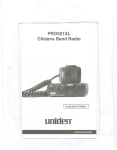
@
@
13. ANTENNA CONNECTOR - This female connector permits connection of the
transmissionline cable male connector (PL-259)to the transceiver.
"
14. PUBLIC ADDRESS - An external 8 ohm 4-watt speaker must be connected to
the "PA SP" jack located on the back of the unit. The speaker must be directed
away from the microphone to prevent feedback.
15. EXTERNAL SPEAKER
The external speaker jack is used for remote receiver
monitoring. The external speaker should have an 8 ohm impedance and be rated
at least 4 watts. When an external speaker is connected, the internal speaker is
disabled.
-
p,'
"
.'
-
This plug permits connection of the DC power to the transceiver. Thesupplied DC Cord's plug is polarized which ensures that power will always be
connected and fused properly.
16~ POWER
OPERATING PROCEDURE TO RECEIVE
1. Be sure that the power source, antenna and microphone are properly connected.
2. Turn the unit on by rotating the Volume control clockwise.
3. Set the channel selector switch to the desired channel.
I
4. Set the Volume control to a comfortable listening level.
5. Listen to the background noise from the speaker. Turn the Squelchcontrol clockwise until the noise disappears (no signal should be present). Leave the control at
~--
_I
-4-
I
-
-
-
i
:--- ~,
I~
.
this setting. The squelch is now properly set. The receiver will remain quiet until a
signal is actually received. Do not advance the control too far, or some weaker
signals will not be heard.
OPERATING PROCEDURE TO TRANSMIT
1. Se.lect;,tpedeslred,~ha(1nel
for tt~,ns,lJ1.ission..,'
. ..
2. If the 'channer' is 'dear, depresf'tfje
"',
,'.
,
"c'
,
"..
phone'al1d'speak
"0
"~ "'.j';.f
r
)
,"
push-to-talk' 'switch bn the side' of 'the micro-';-
.
;'
In,a normal
CAUTION: 'jThl..tfa'n'sceiver
voice'.
,;
,,-.',
.. '"
'
"
Voltag~';';Staiidirig Wave Ratio (V.S.W.R.) -measurement
mustce perlortned' p'ricifto' the use ofth:e transmitte~. A"V.S.W.R." ratio in excess of
2:1 may'dam'age the transmitter.
..
'-' .'. "~,"
",
-'.. ~ . "5,'
'
"
...
OPERATION,O,FSSB
Choose the desired side band frequency by, A; select standard channel (1
"',U"-'
- 40), B;
select Upper or Lower side band by moving AM/SSB switch. Transmit or receive
according to previous instructions.
When receiving a side band transmission you may need to use the Clarifier control to
fine tune that frequency. Rotate the Clarifier clockwise or counterclockwise for
optimum reception.
PREVENTATIVE
MAINTENANCE
At six to twelve month intervals, the following system checks should be made:
1. Check the Standing Wave Ratio (V.S.W.R.)
2. Inspect all electrical connections.
3. Inspect antenna coaxial cable for wear.
4. Inspect all screws and other mounting hardware.
TROUBLE SHOOTI NG
If your PC122XL is not performing up to your expectations, please try these simple steps.
If you still cannot get satisfactory results after reading this manual and following the
trouble shooting steps, you may need to have your unit serviced.
trouble
check
Unit will not turn on.
No power
1. Checkpowercord and all connections.
2. Check power cord fuse.
3. Check vehicle electrical system.
Poor reception
1. Check and adjust Squelch.
2. Check antenna system and cable, connectors.
3. Check operation mode of the radio.
Weak transmission
1. Check antenna system and cable, connectors.
2. Check antenna grounding.
3. Check for corrosion on connectors.
--.----
,.
---
---"-'
-5II!!!!!
~
---
,,'
~
I~
F~
---
-===
""""
If you determine that service is necessary, contact your local dealer or pack the unit in
its original carton. Send it along with a brief, concise description of the problem, your
name, address, phone number, and a copy of the original purchase receipt to the
address listed in the warranty.
SERVICING YOUR CB
,<"
F~'
'".
It is ,th,euser's responsibility~
to see that
.
,'.,this radio is operating at all times in accordance with
theDOTAC Cltfzensaand Radio Seryice regulations. We highly recommend that you consult
a qualified r~ioteleph,one tecl:micianfor service and alignment of this radio. When ordering,
parts:'itis
'
.,
important to specify theccjIT8ct model number and serial number of this radio.'
","
Please refer to the WARNING information on the first page of this manual.
SPECI FICA TIONS
-
GENERAL
Channels
Frequency Range
Frequency Control
: 40 AM, 40 usa, 40 LSB
: 26.965 to 27.405 MHz
: Phase Lock Loop (PLU
synthesizer
Frequency Tolerance: 0.005%
Operating Temp.
: -10°C to +50oc
Microphone
: Plug in type; dynamic
Input Voltage:
13.8 VDC nom. (+ or ground)
Current Drain
: TX: AM full mod., 2.2 A,
SSB 12 watts PEP output, 2 A
RX: AM & SSB with max
audio output 0.6 A
Size
: 6"W x 7%"0 x 2"H
Weight
: 2 lb. 10 oz.
Antenna Connector: UHF, SO-239
Semiconductors:
41 transistors, 7 IC, 49
diodes
LED Meter
: Indicates relative power
output and receive signal
strength
TRANSMITTER
Power Output
Modulation
Intermodulation
Distortion
SSB Carrier
Suppression
Unwanted Sideband: Better than 5OdB
Freq. Response:
300 - 3000 Hz
Output Impedance: 50 ohms, unbalanced
SSB Filter
: 10.695
MHz, 8 pole
monolithic type 6dB @
4.2KHz, 6OdB @ 7.0KHz
RECEIVER
Sensitivity
: SSB: Better than .25 }JV
for 1OdB; (S + N)/N @
greater than 112 watt of
audio output, AM; Better than.5 jJV for 10dB;
(S + N) IN @ greater than
112 watt of audio output
: SSB and AM; 6dB @ 4.2
Selectivity
KHz, 6OdB @ 7.0KHz
Cross Modulation
: More than 5OdB
: More than 75dB
Image Rejection
: AM and SSB; 10.695
I.F. Frequency
MHz
Automatic Gain
: (AGC): less than 1OdB
Control
change in audio output
for inputs from 10 to
500,000 microvolts
: AM maximum of 4W
Squelch
; Adjustable; threshold less
SSB maxirrum of 12W PEP
than .5 }JV
Clarifier
: :t1.5KHz
: Class B amplitude
modulation
Audio Output Power: 3 watts into 8 ohms
: 350 to 2500 Hz
: Lessthan 10% at 3 watts
Freq. Response
: SSB:3rd and 5th order,
better than
25dB, 7th
and 9th order better than
-
- 35dB
Distortion
Internal Speaker
External Speaker
PA System
output
: 16 ohms, round
: (not supplied) 8 ohms
: 3 watts in external 8 ohm
speaker
: Better than ~ 55dB
.
.---.-
-6oe!!!:
--
M
---
/--'
I
,--'"
i'
WARRANTY
UnidenPC122XLCB Radio Australian 2 Year Warranty.
(AcceS$9~e.s ,~
"Note:
Ple~se~1<$epyour sah:)s:-~~~f'~
" ,../
,," ,
,,<
WARRA,NTOR:,Uniden
-,
.,'.,..""";"",,,
., ".~,'...ELEMENTS
')r! 'r;:~~1
H)::t
covered for 90 Days only).
~."..
It 'proVides evidence of warranty.
.
,
A~str~I~:'pty~ Ltd.
"'-':'/',"'-'.1'e;-',"'"',
OF WARRANTY:
'Uniden warrants to the original retail owner for the duration of
(thiswarranty,its PC122XLCBRadio(hereinafterreferredto asthe Produd),to befreefrom
b.:,\i{:;"pefedsln materials and aaftsmanship
:(r;::J:: ':{" ~ ~~
with only the !irritations or exdusions
set out below.
ARRANTY DURATION: This warranty to the original user only shall terminate and be of no
.,further effed Two (2) Years after the date of original retail sale. This warranty will be deemed
invalid if the prodUd Is (A) Damaged or not maintained as reasonable and necessary, (B)
MOdidfied, altered, or used as part of any conversion kits, subassemblies , or any configuration
s not sold by Uniden, (C) Improperly installed, (D) Repaired by someone other than an
authorised Uniden Repair Agent for a defed or malfunction covered by this warranty, (E) Used
In conjunction with any equipment or parts or as part of a system not manufactured by Uniden,
(F) Installed, programmed or serviced by anyone other than an authorised Uniden Repair
Agent, (G) Where the Serial Number label of the produd has been removed or damaged
beyond recognition.
PARTS COVERED: This warranty covers for 2 years; the Transceiver and Microphone only.
All accessories, (Leads, Brackets, Clips, Saews etc), are covered for 90 days only.
STATEMENT OF REMEDY: In the event that the produd does not conform to this warranty
at any time while this warranty is in effed, the warrantor will at its discretion, repair the defect
or replace the produd and return it to you without chrge for parts or service. THIS WARRANTY
DOES NOT COVER OR PROVIDE FOR THE REIMBURSEMENT
OR PAYMENT OF
INCIDENTAL OR CONSEQUENTIAL DAMAGES.
CARD: Ifa warranty card had been included with this produd then please fill
it in and return it to us within 14 days of purchase. Your name and the serial number of the
WARRANTY
prodUd will then be registered in our database and this will help us to process your claim with
greater speed and efficiency should you require warranty service.
\m, t;:',: .; PROCEDURE FOR OBTAINING
PERFORMANCE
OF WARRANTY.
In the event that the
,if;?C,';'Ji!t;rP,rodUd does not conform tcthis warranty, the Produd should be shipped or delivered, freight
oB',<1;::[
"}J' :cpre-paid, with evidence of original purchase, (egI a copy of the sales docket), to the warrantor
at:
UNIDEN
AUSTRAUA
PTY L TD
.
SERVICE
DIVISION
345 Princes Highway, Rockdale, Sydney. NSW 2216.
Ph (02) 599 3100 Fx (02) 599 3278
Customers in'other States should ship or deliver the Product
freight pre-paid to their nearest Uniden Authorised Repair Centre.
(Contact Uniden for the nearest Warranty Agent to you).
Aaelaide (08) 365 2588 Brisbane (07) 290 1188
Melbourne (03) 335 4322
Perth (09) 227 6386
'--
,
UTUAO1549DC
@ Copyright 1992 Uniden Austra!ia,
~. Ltd.
Printed in the Philippines
~
=---
",,'
,