1
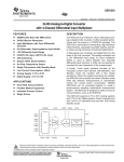
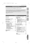
<:::
uniden@
0
,'..
10 Channel
Marine CB Transceiver
,-
f
---
-.-
-
-
------r-
=:=
'",--==
=
r
DESCRIPTION
Your MC2700 represents the most advanced Mobile Station type radio ever designed for use
in the Inshore Boating Radio Communications Service, combined with unique features for use
on a boat. It will operate on any of the 10 frequencies designated as citizens band channels
by the Department of Transport and Communications (DOTAC). Your Model MC2700
features a frequency synthesizing circuit with PHASE LOCK LOOP techniques to assure
ultraprecise frequency control. This radio has been Type Accepted approved by the DOTAC.
WARNING
The Inshore Boating Radio Communications Service is under the jurisdiction of the Department of Transport and Communications (DOTAC). Any adjustments or alterations which
would alter the performance of the transceiver's original DOTAC Type Approval or which
would change the frequency determining method are strictly prohibited. Replacement or
substitution of Crystal, Transistors, IC, Regulator Diodes or any other part of a unique nature,
with parts other than those recommended by us, may cause violation of the technical
regulations of the DOTAC Rules.
INSTAllATION
CAUTION: The UNIDEN
ground battery system.
MC2700 will operate only with nominal
12 volt negative
It is important to carefully determine the most suitable location for your UN I DEN
MC2700 on your vessel. Electrical, mechanical, and environmental considerations
must all be taken into account. You must select the optimum relationship among
these considerations.
Some of the more important
your UNIDEN MC2700 are:
external factors to consider in selecting the location of
1. Select a location that is free from spray and splash.
2. Keep the battery leads as short as possible. Connection directly to the battery is
most desirable. If direct connection cannot be made with the supplied power lead,
any extension should be made with #14 AWG wire. Long extensions should use
larger wire.
3. Keep the antenna lead as short as possible. Long antenna leads can cause sub.
stantialloss of performance for both receiving and transmitting.
4. Locate your antenna as high as possible and clear from metal objects. The reliable
range of coverage is a direct function of antenna height.
-1-
~
r
-- - --- - _.-- -
--
------
1
1
,-,--,
--,
r'
5. Select a location that does not allow the radio to be subjected to direct sunlight
(including that coming through windows).
6. Select a location well away from the ship's compass. Auxiliary speakers also
should be located away from the compass.
ANTENNA
Since the maximum allowable power output of the transmitter is limited by the DOT AC, the
antenna is a very important factor affecting transmission distance. It is for this reason that we
strongly recommend that you install only a quality antenna in your new citizens band system.
Only a properly matched antenna system will allow maximum power transfer from the 50-ohm
transmission line to the radiating element. Your UNIDEN dealer is qualified to assist you in
the selection of the proper antenna to meet your application requirements.
NOTE: The general rules for antennas are: The more gain the greater the range and
the higher above the water line the greater the range. Antennas should be located so
as not to be in proximity to metal objects. Antennas should not have excessively long
coaxial feed cables.
CONNECTING
THE POWER CORDS
After you have carefully considered the various factors affecting your choice of
location, position the radio (with the bracket, microphone, power plug, antenna
plug, and any auxiliary plugs installed) into the sel,ected location to assure there is no
interference with surrounding items. Mark the location of the mounting bracket.
Remove the bracket from the radio and use it as a template to mark the holes to be
drilled for the mounting hardware. Drill the holes and mount the bracket with
hardware compatible with the material of the mounting surface. Install the power
cable (red is +, black is -), antenna, all other auxiliary cables and accessories.
Install the radio into the mounting bracket and connect all cables and accessories to
the appropriate jacks and connectors.
OPERATING PROCEDURE TO RECEIVE
1. Be sure that the power source, antenna and microphone are connected to the
proper connectors before going to the next steps.
2. Turn the unit ON by rotating the Volume Control clockwise.
3. Set the Channel Selector Switch to the desired channel.
4. Set the Volume Control to a comfortable listening level.
5. Listen to the background noise from the speaker. Turn the Squelch Control
slowly clockwise until the noise JUST disappears (no signal should be present).
Leave the control at this setting. The SQUELCH is now properly adjusted. The
receiver will remain quiet until a signal is actually receive"d. Do not advance the
control too far, or some of the weaker signals will not be heard.
-2-
1
Tt
_h_-
-.-_.
OPERATING
---
PROCEDURE TO TRANSMIT
CAUTION
The transmitter Voltage Standing Wave Ratio (V.S.W.R.) measurement must
be performed prior to the use of the transmitter. A V.S.W.R. ratio in excess
of 2:1 may damage the transmitter.
1. Be sure the operator has read and understands DOTAC Rules and Regulations prior to
operating the transmitter.
2. Select the desired channel.
3. If the channel is clear, depress the push-to~talk switch on the microphone and
speak in a normal voice.
OPERATOR TROUBLESHOOTING
Should the unit malfunction or not perform properly, the operator should perform
the procedures indicated below:
1. If the transceiver is completely inoperative.
* Check the power cord and fuse.
2. If trouble is experienced with receiving.
* Check ON/OFF VOLUMECONTROLsetting.
* Besure SQUELCH is adjusted properly. Isthe radio over-squelched?
*
Check to see that the radio is switched to an operational mode.
3. If trouble is experienced with transmitting.
* Check to see that the transmission line (coaxial cable) is securely connected to
the ANTENNA CONNECTOR.
* Be sure that the antenna is fully extended for proper operation.
* Be sure that all transmission line (coaxial cable) connections are secure and free
of corrosion.
-3-
'9::
--
-----
I
1
,
=",---=
SPECI FICA TIONS
GENERAL
RECEIVER
Channels
RADIOTELEPHONY: 10
Frequency
RADIOTELEPHONY: 27.680 - 27.980
Microphone
: SOOohm, Dynamic
Type
: 3 inches, 16 ohms
Speaker
Size
: 1S4(W) x S2(H) x
192(D) mm
Weight
: 1.1 Kgs
Accessories
: DC Power Cable with
Built-in Fuse, Microphone, Microphone
Hanger with Screws,
Mounting Bracket
with Screws
Maximum Sensitivity
Threshold Squelch
Sensitivity
Tight Squelch Sensitivity
Adjacent Channel Selectivity
at :t1 OkHz
Image Rejection Ratio
-910kHz
: 1.0JlV
:1.0JlV
: 2.0 JlV
: 60 dB
: 90 dB
Audio Output Power
a. Maximum
: SW
b. 10% THD
:4W
S-Meter Sensitivity at "4th digit": 100 JlV
TRANSMITTER
Frequency Tolerance
2SoC 13.8V
R F Power Output
: :to.OOOS %
:4W
FRONT PANEL CONTROLS AND INDICATOR
6
I
uniden
~
8
9
:1a
::::J
I
~
SEA-DOLPHIN
"~R/NE CB T.RANSCE/VER
5
-4-
--:r
I
-
-----
f
,
-
1. MICROPHONE CONNECTOR: Receptacle for microphone connection.
2. ON/OFF-VOLUME: Turns power on to radio and allows adjustment
desired listening level with clockwise rotation.
to the
3. SQUELCH: Used to quiet background noise when no signal is being received.
Proper adjustment is such that the control is advanced only slightly beyond the
point where the background noise is marginally quieted.
4. RF GAIN: This control is used primarily to optimize reception in strong signal
areas. Gain is reduced by counter.clockwise rotation of the control.
5. CHANNELSELECTION CONTROL: This control selects the desired channel for
transmission and reception. Allchannels except channel 88, may be used for communications between stations. Channel 88 has been reserved by the DOTACfor emergency
communications involvingthe immediate safety of individuals or immediate protection of
property. This is a DOTAC rule and applies to all operators of citizens band radios.
6. ANL (AUTOMATIC NOISE LlMITER) ON/OFF SWITCH: The ANL circuit
reduces most undesirable interference noises.
7. NB (NOISE BLANKER)ON/OFF SWITCH: The NB is very effective for reducing repetitive impulse noise such as ignition noise.
8. CHANNEL 88 ON/OFF SWITCH: This switch selects channel 88, Channel
Indication will disappear and CH 88 LED will flash.
9. S/RF METER: This LED meter shows the relative strength ef the received
signal or transmitted power.
10. CHANNEL INDICATOR:
number in use.
Light Emitting Diode(LED) indicates the channel
-5-
I!
'
=f
.--'-'
-
--
-----
1--
r
----------
.
REAR PANEL CONNECTORS
[
@
1. ANTENNA CONNECTOR: This female connector permits' connection
transmission line cable male connector (PL-259) to the transceiver.
of the
2. EXTERNAL SPEAKER: The External Speaker Jack is used for remote receiver
monitoring. The external speaker should have 8-ohm impedance and be rated to
handle at least 4.0 watts. When the external speaker is plugged in, the internal
speaker is automatically disconnected.
3. POWER: This jack permits connection of the D.G. power to the transceiver. A
power cord with polarized plug is supplied with the radio. The polarized plug
ensures that the power will always be connected properly.
SERVICING
YOUR TRANSCEIVER
The technical information, diagrams and charts will be supplied upon request. It is the user's
responsibility to see that this radio is operating at all times in accordance with the DOT AC
Inshore Boating Radio Communications Service regulations. We highly recommend that you
consult a qualified radio telephone technician for the servicing and alignment of this marine
radio product.
Please refer to the WARN ING information
Manual.
contained
in the 1st page of this Owner's
(NOTE: When ordering parts, it is essential to specify the correct model number and
serial number of the unit.)
-6-
q:
j
- -.-
--
~-
I
1
---
f
WARRANTY
Uniden MC-2700 Marine CB Radio Australian 1 Year Warranty.
(Accessories are covered for 90 days only).
Note: Please keep your sales docket as it provides evidence of warranty.
WARRANTOR:
Uniden Australia Pty. Ltd.
ELEMENTS OF WARRANTY: Uniden warrants to the original retail owner for the duration of
this warranty, its MC-2700 Marine CB Radio (hereinafter referred to as the Product), to be free
from defects in materials and craftsmanship with only the limitations or exclusions set out
below.
WARRANTY DURATION: This warranty to the original user only shall terminate and be of
no further effect One (1) Year after the date of original retail sale. This warranty will be deemed
invalid if the product is (A) Damaged or not maintained as reasonable and necessary, (B)
Modified, altered, or used as part of any conversion kits, subassemblies, or any configurations
not sold by Uniden, (C) Improperly installed, (D) Repaired by someone other than an
authorised Uniden Repair Agentfor a defector malfunction covered by this warranty, (E) Used
in conjunction with any equipment or parts or as part of a system not manufactured by Uniden,
(F) Installed, programmed or serviced by anyone other than an authorised Uniden Repair
Agent, (G) Where the Serial Number label of the product has been removed or damaged
beyond recognition.
rc'
m
!}
~
~
~
I
i!!
I
r
PARTS COVERED: This warranty covers for 1 year; the Transceiver and Microphone only.
All accessories, (Leads, Brackets, Clips, Screws etc). are covered for 90 days only.
STATEMENT OF REMEDY: In the event that the product does not conform to this warranty
at any time while this warranty is in effect, the warrantor will at its discretion, repair the defect
or replace the product and return it to you without charge for parts or service. THIS
WARRANTY DOES NOT COVER OR PROVIDE FOR THE REIMBURSEMENT OR PAY.
MENT OF INCIDENTAL OR CONSEQUENTIAL DAMAGES.
WARRANTY CARD: If a warranty card had been included with this product then please fill
it in and return it to us within 14 days of purchase. Your name and the serial number of the
product will then be registered in our database and this will help us to process your claim with
greater speed and efficiency should you require warranty service.
PROCEDURE FOR OBTAINING PERFORMANCE OF WARRANTY. In the event that the
Product does not conform to this warranty, the Product should be shipped or delivered, freight
pre-paid, with evidence of original purchase, (eg/a copy of the sales docket), to the warrantor
at:
UNIDENAUSTRAUA PTY LTD . SERVICE DIVISION
345 Princes Highway, Rockdale, Sydney. NSW 2216.
Ph (02) 599 3100 Fx (02) 599 3278
Customers in other States should ship or deliver the Product
freight pre-paid to their nearest Uniden Authorised Repair Centre.
(Contact Uniden for the nearest Warranty Agent to you).
Adelaide (08) 365 2588 Brisbane (07) 290 1188
Melbourne (03) 335 4322 Perth (09) 227 6386
UTUA01307AZ
@ Copyright 1992 Uniden Australia Pty. Ltd.
---
Printed in the Philippines
~
I
I.