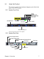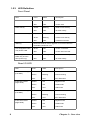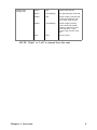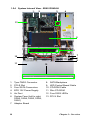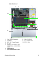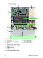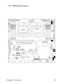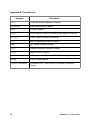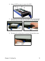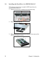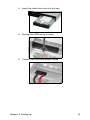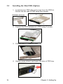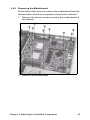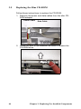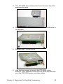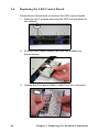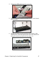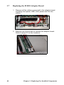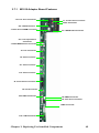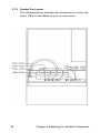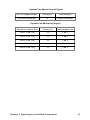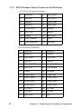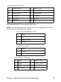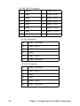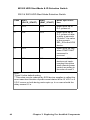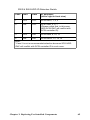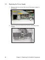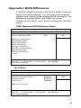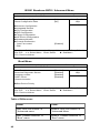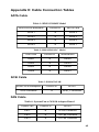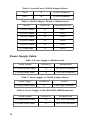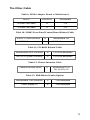
1
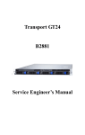
Transport GT24
B2891
Service Engineer’s Manual
PREFACE
Copyright
This publication, including all photographs, illustrations, and software, is protected under international copyright laws, with all rights
reserved. Neither this manual, nor any material contained herein,
may be reproduced without written consent of the manufacturer-.
Copyright 2005
Version 1.0
Disclaimer
Information contained in this document is furnished by TYAN Computer Corporation and has been reviewed for accuracy and reliability
prior to printing. TYAN assumes no liability whatsoever, and disclaims any express or implied warranty, relating to sale and/or use of
TYAN products including liability or warranties relating to fitness for
a particular purpose or merchantability. TYAN retains the right to
make changes to product descriptions and/or specifications at any
time, without notice. In no event will TYAN be held liable for any
direct or indirect, incidental or consequential damage, loss of use,
loss of data or other malady resulting from errors or inaccuracies of
information contained in this document.
Trademark Recognition
All registered and unregistered trademarks and company names
contained in this manual are property of their respective owners
including, but not limited to the following.
TYAN and Transport GT24 B2891 are trademarks of TYAN Computer Corporation.
AMD, Opteron, and combinations thereof are trademarks of AMD
Corporation.
Phoenix, PhoenixBIOS, and combinations thereof are trademarks of
Phoenix Technologies.
Microsoft Windows is a trademark of Microsoft Corporation.
IBM, PC, AT, PS/2 are trademarks of IBM Corporation.
Winbond is a trademark of Winbond Electronics Corporation.
Portable Document Format (PDF) is a trademark of Adobe Corporation.
Federal Communications Commission (FCC)
Notice for the USA Compliance Information Statement (Declaration of Conformity Procedure) DoC FCC
Part 15: This device complies with part 15 of the FCC
Rules
Operation is subject to the following conditions:
1) This device may not cause harmful interference, and
2) This device must accept any interference received including interference that may cause undesired operation. If this equipment does
cause harmful interference to radio or television reception, which
can be determined by turning the equipment off and on, the user is
encouraged to try one or more of the following measures:
– Reorient or relocate the receiving antenna.
– Increase the separation between the equipment and the
receiver.
– Plug the equipment into an outlet on a circuit different from
that of the receiver.
Consult the dealer on an experienced radio/television technician for
help.
Notice for Canada
This apparatus complies with the Class B limits for radio interference
as specified in the Canadian Department of Communications Radio
Interference Regulations. (Cet appareil est conforme aux norms de
Classe B d’interference radio tel que specifie par le Ministere Canadien des Communications dans les reglements d’ineteference
radio.)
Notice for Europe (CE Mark) This product is in conformity
with the Council Directive 89/336/EEC, 92/31/EEC
(EMC).
CAUTION: Lithium battery included with this board. Do not puncture,
mutilate, or dispose of battery in fire. Danger of explosion if battery
is incorrectly replaced. Replace only with the same or equivalent
type recommended by manufacturer. Dispose of used battery
according to manufacturer instructions and in accordance with your
local regulations.
ii
About this Manual
This manual provides you with instructions on installing your
Transport GT24, and consists of the following sections:
Chapter 1:
Provides an Introduction to the Transport GT24
B2891 bare-bones, packing list, describes the
external components, gives a table of key components, and provides block diagrams of the system.
Chapter 2:
Covers procedures on installing the CPU, memory modules, an optional PCI card, and hard
drives.
Chapter 3:
Covers removal and replacement procedures for
pre-installed components.
Appendix:
Describes the differences between mainboard
BIOS and system BIOS. The cable connection
tables are also provided for reference of system
setup.
Conventions
The following conventions are used in the manual:
Note: Calls attention to important information.
Warning: P r o v i de s i n fo r m at i on t o pr e v e nt h ar m
t o us e r or da m ag e t o eq u i pm e nt .
iii
SAFETY INFORMATION
Before installing and using the Transport GT24, take note of the following precautions:
– Read all instructions carefully.
– Do not place the unit on an unstable surface, cart, or stand.
– Do not block the slots and opening on the unit, which are provided for ventilation.
– Only use the power source indicated on the marking label. If
you are not sure, contact the Power Company.
– The unit uses a three-wire ground cable, which is equipped
with a third pin to ground the unit and prevent electric shock.
Do not defeat the purpose of this pin. If your outlet does not
support this kind of plug, contact your electrician to replace
your obsolete outlet.
– Do not place anything on the power cord. Place the power
cord where it will not be in the way of foot traffic.
– Follow all warnings and cautions in this manual and on the
unit case.
– Do not push objects in the ventilation slots as they may touch
high voltage components and result in shock and damage to
the components.
– When replacing parts, ensure that you use parts specified by
the manufacturer.
– When service or repairs have been done, perform routine
safety checks to verify that the system is operating correctly.
– Avoid using the system near water, in direct sunlight, or near
a heating device.
– Cover the unit when not in use.
iv
Table of Contents
Chapter 1:Overview
1.1
1.2
1.3
1.4
1.5
About the Transport GT24 B2891 . . . . . . . . . . . . . . . . . . . . . . . . . 1
Product Models . . . . . . . . . . . . . . . . . . . . . . . . . . . . . . . . . . . . . . . . 2
Features . . . . . . . . . . . . . . . . . . . . . . . . . . . . . . . . . . . . . . . . . . . . . . 3
Unpacking . . . . . . . . . . . . . . . . . . . . . . . . . . . . . . . . . . . . . . . . . . . . 5
About the Product . . . . . . . . . . . . . . . . . . . . . . . . . . . . . . . . . . . . . . 7
1.5.1 System Front View . . . . . . . . . . . . . . . . . . . . . . . . . . . . . . . 7
1.5.2 System Rear View . . . . . . . . . . . . . . . . . . . . . . . . . . . . . . . . 7
1.5.3 LED Definition . . . . . . . . . . . . . . . . . . . . . . . . . . . . . . . . . . 8
1.5.4 System Internal View . . . . . . . . . . . . . . . . . . . . . . . . . . . . 10
1.5.5 Motherboard Layout . . . . . . . . . . . . . . . . . . . . . . . . . . . . . 13
1.5.6 Motherboard Block Diagram . . . . . . . . . . . . . . . . . . . . . . . 15
Chapter 2:Setting Up
2.1
2.2
2.3
2.4
2.4
2.0.1 Before You Begin . . . . . . . . . . . . . . . . . . . . . . . . . . . . . . . . 17
2.0.2 Work Area. . . . . . . . . . . . . . . . . . . . . . . . . . . . . . . . . . . . . . 17
2.0.3 Tools . . . . . . . . . . . . . . . . . . . . . . . . . . . . . . . . . . . . . . . . . . 17
2.0.4 Precautions . . . . . . . . . . . . . . . . . . . . . . . . . . . . . . . . . . . . . 18
Rack Mounting . . . . . . . . . . . . . . . . . . . . . . . . . . . . . . . . . . . . . . . 19
2.1.1 Installing the Server in a Rack. . . . . . . . . . . . . . . . . . . . . . 19
Installing Motherboard Components. . . . . . . . . . . . . . . . . . . . . . . 23
2.2.1 Removing the Chassis Cover. . . . . . . . . . . . . . . . . . . . . . . 23
2.2.2 Installing the CPU, Heatsink and Air Duct . . . . . . . . . . . . 24
2.2.3 Installing the Memory . . . . . . . . . . . . . . . . . . . . . . . . . . . . 27
2.2.4 Installing a PCI Card . . . . . . . . . . . . . . . . . . . . . . . . . . . . . 28
Installing the Hard Drive for B2891G24S4H/U4H . . . . . . . . . . . 30
Installing the Hard Drive for B2891G24S4-LC . . . . . . . . . . . . . . 32
Installing the Slim FDD (Option) . . . . . . . . . . . . . . . . . . . . . . . . . 34
Chapter 3:Replacing Pre-Installed Components
3.1
3.2
3.3
3.4
3.5
Introduction . . . . . . . . . . . . . . . . . . . . . . . . . . . . . . . . . . . . . . . . . . 37
3.1.1 Work Area . . . . . . . . . . . . . . . . . . . . . . . . . . . . . . . . . . . . . 37
3.1.2 Tools . . . . . . . . . . . . . . . . . . . . . . . . . . . . . . . . . . . . . . . . . 37
3.1.3 Precautions. . . . . . . . . . . . . . . . . . . . . . . . . . . . . . . . . . . . . 38
Disassembly Flowchart . . . . . . . . . . . . . . . . . . . . . . . . . . . . . . . . . 39
Removing the Cover . . . . . . . . . . . . . . . . . . . . . . . . . . . . . . . . . . . 40
Replacing Motherboard Components . . . . . . . . . . . . . . . . . . . . . . 41
3.4.1 Disconnecting All Motherboard Cables . . . . . . . . . . . . . . 41
3.4.2 Removing the Motherboard . . . . . . . . . . . . . . . . . . . . . . . . 43
Replacing the Slim CD-ROM . . . . . . . . . . . . . . . . . . . . . . . . . . . . 44
v
3.6
3.7
3.8
3.9
Replacing the LED Control Board . . . . . . . . . . . . . . . . . . . . . . . . 46
Replacing the M1010 Adapter Board . . . . . . . . . . . . . . . . . . . . . . 48
3.7.1 M1010 Adapter Board Features. . . . . . . . . . . . . . . . . . . . . 49
3.7.2 System Fan Layout . . . . . . . . . . . . . . . . . . . . . . . . . . . . . . 50
3.7.3 M1010 Adapter Board Connector Pin Definition . . . . . . . 52
Replacing the SATA or SCSI Backplane . . . . . . . . . . . . . . . . . . . 57
3.8.1 SATA Backplane (M1204) Features . . . . . . . . . . . . . . . . . 59
3.8.2 SCSI Backplane (M1205) Features . . . . . . . . . . . . . . . . . . 62
Replacing the Power Supply . . . . . . . . . . . . . . . . . . . . . . . . . . . . . 66
Appendix I: BIOS Differences
Appendix II: Cable Connection Tables
Technical Support
vi
Chapter 1: Overview
1.1
About the Transport GT24 B2891
Congratulations on your purchase of the TYAN TransportTM
GT24 (B2891), a highly-optimized rack-mountable barebone
system. The Transport GT24 (B2891) offers the latest in dual
processor server systems, providing a rich feature set and
incredible performance. Leveraging advanced technology
from AMD® and nVIDIA, the Transport GT24 (B2891) based
server system are capable of offering scalable 32 and 64-bit
computing, high-bandwidth memory design, and a lightningfast PCI Express bus implementation. The TransportTM GT24
(B2891) not only empowers your company in today’s
demanding IT environment but also offers a smooth path for
future application usage.
TYAN is also proud to deliver the TransportTM GT24 (B2891)
in two flavors: SCSI and SATA versions. Both versions can
support up to four (4) hot-swap hard drives, one (1) slim CDROM and one (1) optional slim floppy disk drive (not
included). The TransportTM GT24 (B2891) uses TYAN’s latest
tooling-made chassis featuring a robust structure, tool-less
and modularized design, and a solid mechanical enclosure.
All of this provides the TransportTM GT24 (B2891) the power
and flexibility to meet the needs of nearly any server application.
Chapter 1: Overview
1
1.2
Product Models
Model
HDD Bays
Hot-Swap
Support
HDD
Backplane
B2891G24U4H
Removable,
4 HDDs
Yes
4-port Ultra
SCSI
B2891G24S4H
Removable,
4 HDDs
Yes
4-port SATA
B2891G24S4-LC
Internal (Fixed),
4 HDDs
No
None
B2891G24S4H
B2891G24U4H
B2891G24S4-LC
2
Chapter 1: Overview
1.3
Features
Enclosure
• Industry 19” rack-mountable 1U
chassis storage bay
– (4) 3.5” HDD bays
– (1) slim line CD-ROM bay
– (1) slim line FDD bay
• Dimension: D 25.4 x W 17.2 x H
1.72 inch (645x436x43.6mm)
– HDD active LED
• Switches
– Power switch
– Reset switch
Storage Controller
• Model B2891G24U4H:
– Add-on Tyan M7901 SCSI controller card (Adaptec AIC7901
single channel Ultra320 SCSI
Processors
controller), connected to Tyan
• Supports one or two AMD OpterTARO SO-DIMM
TM 200 series processors
on
– Supporting HostRAID 0,1 & 10
• Model B2891G24S4H/S4-LC
Chipset
– Two dual-port SATAII controllers
• nVIDIA nForce4 Professional +
integrated in nVIDIA nForce4 Pro
AMD-8131 Hyper Transport PCI-X
chip
Tunnel
–
Supporting 3Gb/s per port
• Winbond W83627HF Super I/O chip
– Supporting RAID 0, 1, 0+1 and
• ADT7463 Hardware monitor IC
nVIDIA Morphing RAID (allowing
Memory
to change the RAID type on the
• Eight 184-pin 2.5-Volt DDR DIMM
fly)
sockets
Storage
• Supports up to 16GB of Registered,
• Model B2891G24U4H: SCSI verECC DDR400/333 memory
sion, supports up to 4 hot-swappa• Supports Chipkill technology
ble Ultra320/160/ SCSI HDDs
Expansion Slots
• Model B2891G24S4H: SATA ver• One 64-bit 100MHz (3.3V) PCI-X
sion, supports up to 4 hot-swappaslot, supporting low profile card (for
ble SATA HDDs
S4H, S4-LC sku only)
• Model B2891G24S4-LC: SATA ver• One PCI-E x16 slot
sion, supports up to 4 internal SATA
• Tyan TARO SO-DIMM connector for
HDDs.
add-on storage controller card
• Optional slim line CD-ROM, DVDROM and FDD
Back I/O Ports
• One keyboard & one PS/2 mouse
ports
• Two RJ45 10/100/1000 Base-T port
with activity LED
• Two USB 2.0 ports
• One 9-pin UART serial port
• One 15-pin VGA port
Front Panel Features
• I/O
– (2) USB 2.0 ports
• LED indicators
– Power LED
– (2) LAN LEDs
Chapter 1: Overview
.
Networking
• (2) Gigabit Ethernet ports (Broadcom BCM5704 dual port controller)
connected to 133MHz PCI-X bus
Video
• ATI RAGE XL PCI graphics controller
• 8MB Frame Buffer of video memory
Motherboard
• Tyan Thunder K8SRE S2891G2NR
• E-ATX footprint (13” x 12”)
3
Server Management
Regulatory
• Automatic fan speed control
• Chassis intrusion alert
• Supports Tyan Server Management
(TSM)
• Tyan SMDC, IMPI v1.5 compliant
remote server management (option)
• FCC Class B (Declaration of Conformity)
• CE (Declaration of Conformity)
Power Supply
• EPS 12V, 1U, 500W with PFC
• 100V~240V AC input
4
Environment Temperature
• Operating temperature 5oC~35oC
• Non-operating temperature -40oC ~
70oC
Chapter 1: Overview
1.4
Unpacking
If any items are missing or appear damaged, contact your
retailer or browse to TYAN’s Web site for service:
http://www.tyan.com.
The Web site also provides information on other TYAN products, plus FAQs, compatibility lists, BIOS settings, and more.
1 x Tyan driver CD
HDD Screws
Mounting Ears & Screws
FDDs
1pcs for S4H, S4-LC sku
3pcs for U4H sku
SMDC Kit
Power Cords
Left to right: Europe, US
FDD Kit
FDD Cable
FDD Backplane
FDD Backplane Cable
FDD Rails & Screws
Chapter 1: Overview
5
Barebone Manual
Mainboard Manual
Heatsink x 2
Rail Kit
Front
Rear
Sliding Brackets
Front L-Bracket x 2
Rear L-Bracket x 2
Mounting Bracket x 4
Screws Kit
Sliding Rails x 2
6
Chapter 1: Overview
1.5
About the Product
This section contains the hardware diagrams and a block diagram of the GT24 system.
1.5.1 System Front View
Reset
switch
Warning LED
HDD activity LED
Power LED
*Reserved
USB ports
CD-ROM Drive
LAN LEDs
Power switch
Hard Drive Bay x 4
*Reserved: Reserved LED for future upgrade
1.5.2 System Rear View
Power Supply Socket
Power Supply LED
PS/2 Mouse/Keyboard Ports
PCI-E Slot
PCI-X Slot
USB Port
Serial Port
LAN Port x 2
VGA Port
Chapter 1: Overview
7
1.5.3 LED Definition
Front Panel
LED
Color
State
Description
Power
Green
ON
Power ON
OFF
OFF
Power OFF
Amber
Blinking
HDD access activity
OFF
OFF
No disk activity
Green
ON
LAN connected
Green
Blinking
LAN access activity
OFF
OFF
LAN disconnected
HDD Activity
LAN1/LAN2 Activity
Warning
Reserved LED for future upgrade. It is not functional in
the B2891 barebone now.
Hot Swappable HDD
Tray Power LED
Green
ON
Power connected
OFF
OFF
Power disconnected
Amber
Blinking
HDD access activity
OFF
OFF
No disk activity
Hot Swappable
HDD Tray Access
LED (U4H only)
Rear I/O LED
LED
Color
State
Description
RJ45 NIC1 Linkage
(Left Side)
Green
ON
LAN linked
Green
Blinking
LAN accessing
OFF
OFF
No LAN linked
Amber
ON
Gigabit mode
Green
ON
100M mode
OFF
OFF
10M mode
Green
ON
LAN linked
Green
Blinking
LAN accessing
OFF
OFF
No LAN linked
Amber
ON
Gigabit mode
Green
ON
100M mode
OFF
OFF
10M mode
RJ45 NIC1 Mode
(Right Side)
RJ45 NIC2 Linkage
(Left Side)
RJ45 NIC2 Mode
(Right Side)
8
Chapter 1: Overview
Delta Power
Supply LED
Green
ON
Output ON and OK
Green
1Hz Blinking
AC present/Only 5Vsb ON
Amber
ON
Power supply critical event
causing a shutdown: failure, OCP, OVP, fan fail
Amber
1Hz Blinking
Power supply warning
event where the power
supply continues to operate: high temp., high
power, high current, slow
fan
OFF
OFF
No AC power
NOTE: “Right” or “Left” is viewed from the rear.
Chapter 1: Overview
9
1.5.4 System Internal View - B2891G24S4H
1
2
3
4
13
5
6
7
8
9
10
11
1.
2.
3.
4.
5.
6.
Tyan TARO Connector
PCI-E Slot
Four SATA Connectors
EPS 12V Power Supply
Air Duct
System Fans (Left to right:
FAN5, FAN4, FAN3, FAN2,
FAN1)
7. Adapter Board
10
12
8.
9.
10.
11.
12.
13.
SATA Backplane
LED Control Board Cable
CD-ROM Cable
Slim CD-ROM
Four SATA HDDs
PCI-X Slot
Chapter 1: Overview
B2891G24S4-LC
3
1
2
10
4
5
6
7
8
1.
2.
3.
4.
5.
Tyan TARO Connector
PCI-E Slot
EPS 12V Power Supply
Air Duct
System Fans (Left to right:
FAN5, FAN4, FAN3, FAN2,
FAN1)
6. Adapter Board
7. LED Control Board Cable
Chapter 1: Overview
9
8. Slim CD-ROM
9. Four SATA HDDs
10. PCI-X Slot
11
B2891G24U4H
1
3
2
9
4
5
6
7
8
10
11
1.
2.
3.
4.
5.
Tyan TARO Connector
PCI-E Slot
EPS 12V Power Supply
Air Duct
System Fans (Left to right:
FAN5, FAN4, FAN3, FAN2,
FAN1)
6. Adapter Board
7. SCSI Backplane
8. LED Control Board Cable
12
12
9.
10.
11.
12.
SCSI daughter card
CD-ROM Cable
Slim CD-ROM
Four SCSI HDDs
Chapter 1: Overview
1.5.5 Motherboard Layout
FAN5
J53
J140
PPCIX-100
AMD 8131
PCI-X Bridge
ATI
RAGE XL
J110
J48
FAN8
J77
J13
FAN9
Chapter 1: Overview
JA14
J87
FAN7
J42
LPT
NFroce
Pro 2200
J112
Winbond
w8362HF
FDD
J14
J85
PCIE X16
SATA3 SATA1
SATA2 SATA0
J113
IDEP
IDES
J25
CPU0 DIMMB2
CPU0 DIMMB1
CPU0
CPU1
J75 J73
J139
FAN6
FAN4
CPU0 DIMMA2
FAN3
CPU0 DIMMA1
CPU1 DIMMA1
CPU1 DIMMA2
CPU1 DIMMB1
SMDC
CPU1 DIMMB2
FAN1
FAN2
13
Jumpers & Connectors
Jumper
Function
J14
Onboard Buzzer/Speaker Header
J25/J140
USB Front Panel Header
J42
COM2 Header
J53
PCI-X Slot & TARO Connector Bus Speed Override
J73/J75
Front Panel LAN LED Headers
J77
INTR-Chassis Intrusion Header
J85
ATI Video Disable Jumper
J87
Gigabit Ethernet Disable Jumper
J112
Clear CMOS Jumper
J113
PCI Express x16 Slot with Riser Card support
J139
Front Panel Header
TARO Connector
Connector for TYAN TARO SO-DIMM Controller
Cards
14
Chapter 1: Overview
1.5.6 Motherboard Block Diagram
Chapter 1: Overview
15
Memo
16
Chapter 1: Overview
Chapter 2: Setting Up
2.0.1 Before You Begin
This chapter explains how to install the CPU, CPU heatsink,
memory modules, and hard drives. Instructions on inserting a
PCI card are also given.
Take note of the precautions mentioned in this section when
installing your system.
2.0.2 Work Area
Make sure you have a stable, clean working environment.
Dust and dirt can get into components and cause malfunctions. Use containers to keep small components separated.
Putting all small components in separate containers prevents
them from becoming lost. Adequate lighting and proper tools
can prevent you from accidentally damaging the internal
components.
2.0.3 Tools
The following procedures require only a few tools, including
the following:
•
•
A cross head (Phillips) screwdriver
A grounding strap or an anti-static pad
Most of the electrical and mechanical connections can be disconnected using your fingers. It is recommended that you do
not use needle-nosed pliers to remove connectors as these
can damage the soft metal or plastic parts of the connectors.
Chapter 2: Setting Up
17
2.0.4 Precautions
Components and electronic circuit boards can be damaged
by discharges of static electricity. Working on a system that is
connected to a power supply can be extremely dangerous.
Follow the guidelines below to avoid damage to the
Transport GT24 or injury to yourself.
•
Ground yourself properly before removing the top
cover of the system. Unplug the power from the
power supply and then touch a safely grounded
object to release static charge (i.e. power supply
case). If available, wear a grounded wrist strap. Alternatively, discharge any static electricity by touching
the bare metal chassis of the unit case, or the bare
metal body of any other grounded appliance.
•
Avoid touching motherboard components, IC chips,
connectors, memory modules, and leads.
•
The motherboard is pre-installed in the system.
When removing the motherboard, always place it on
a grounded anti-static surface until you are ready to
reinstall it.
•
Hold electronic circuit boards by the edges only. Do
not touch the components on the board unless it is
necessary to do so. Do not flex or stress circuit
boards.
•
Leave all components inside the static-proof packaging that they ship with until they are ready for installation.
•
After replacing optional devices, make sure all
screws, springs, or other small parts are in place and
are not left loose inside the case. Metallic parts or
metal flakes can cause electrical shorts.
Notes:
• All connectors are keyed to only attach one way.
• Always use the correct screw size as indicated in the
procedures.
18
Chapter 2: Setting Up
2.1
Rack Mounting
The Transport GT24 can be mounted in a rack using the supplied rack mounting kit.
Rack mounting kit
Sliding Rails x 2:
Sliding Brackets x 4 (Front x 2, Rear x 2)
Mounting Ears x 2
Screws Kit x 1
Mounting Brackets x 4
2.1.1 Installing the Server in a Rack
Follow these instructions to mount the Transport GT24
B2891 into an industry standard 19" rack.
NOTE: Before mounting the Transport GT24 in a rack, ensure
that all internal components have been installed and that the
unit has been fully tested. Maintenance can be performed on
the unit while in a rack but it is preferable to install the device
in a fully operational condition.
1. Screw the mounting ear to each side of Transport GT24
as shown using 2 screws from the supplied screws kit.
Mounting Ears
Chapter 2: Setting Up
19
2. Screw the sliding brackets to the sliding rails.
Sliding Brackets
Front
Rear
3. Slide the sliding rail to each side of the Transport GT24.
4. Screw the sliding rail to each side using 2 screws as
shown.
20
Chapter 2: Setting Up
5. Locate the mounting bracket from the supplied kit and
screw it to the rack using 2 screws on each side. Be careful that the mounting bracket should be secured from
the inside of rack, not from the outside of rack. See the
picture below for the correct direction.
Mounting Bracket
Chapter 2: Setting Up
21
6. Lift and insert the unit into place in the rack (A). Ensure
the unit is completely inserted into the rack (B). Then
screw the unit into place as shown (C).
A
B
C
Note: To avoid injury, it is strongly recommended that two people lift the
Transport GT24 into place while a third person screws it to the rack.
22
Chapter 2: Setting Up
2.2
Installing Motherboard Components
This section describes how to install components on to the
motherboard, including CPU, memory modules and PCI card.
2.2.1 Removing the Chassis Cover
Follow these instructions to remove the Transport GT24
chassis cover.
1. Release the screw on the back side. Then slide the chassis cover in the direction of arrow.
2. Lift the cover off.
A
Chapter 2: Setting Up
B
23
2.2.2 Installing the CPU, Heatsink and Air Duct
Follow these instructions to install the CPU, CPU heatsink
and air duct.
1. After removing the pre-installed air duct, locate the CPU
sockets.
CPU socket
2. Pull the CPU lever up to unlock the CPU socket.
24
Chapter 2: Setting Up
3. Place the CPU in the CPU socket, ensuring that pin 1 is
located as shown in the following illustration.
4. Press the CPU socket lever down in the direction shown
to secure the CPU.
Chapter 2: Setting Up
25
5. Align the heatsink screw holes with the holes on the
motherboard and insert two heatsink screws as shown.
6. Replace the air duct over the heatsink and secure it to
the motherboard using two screws.
26
Chapter 2: Setting Up
2.2.3 Installing the Memory
Follow these instructions to install the memory modules on
the motherboard.
1. Locate the memory slots on the motherboard.
Memory Slots
2. Press the memory slot locking levers in the direction of
the arrows as shown in the following illustration.
3. Align the memory module with the slot. The module has
indentations that align with notches in the slots.
Chapter 2: Setting Up
27
4. Insert the memory module into the slot as shown.
When inserted properly, the memory slot locking levers lock
automatically onto the indentations at the ends of the module.
2.2.4 Installing a PCI Card
There are two PCI slots on the rear panel of GT24. The left
slot is for PCI-E card while the right one is for PCI-X card.
The procdures for installing PCI -E and PCI-X cards are the
same. The follwoing instructions are for PCI-E card installation. You may refer to the procedures below for PCI-X installation.
1. Push the tab of PCI slot on the rear panel in the direction
as shown to release the bracket.
28
Chapter 2: Setting Up
2. Move the bracket to left as shown.
3. Insert the PCI-E card as shown.
4. Push the tab of PCI slot in the direction as shown to fix
PCI-E card.
Chapter 2: Setting Up
29
2.3
Installing the Hard Drive for B2891G24S4H/U4H
The Transport GT24 barebone system supports Serial ATA
and SCSI hard drives.
Follow these instructions to install a SATA or SCSI hard drive
for model B2891G24U4H/B2891G24S4H.
1. Press the locking lever latch in the direction of arrow (A)
and then pull the locking lever open (B).
B
A
2. Slide the drive tray out.
3. Place a hard drive into the drive tray.
30
Chapter 2: Setting Up
4. Using 4 HDD screws to secure the HDD.
5. Reinsert the drive tray into the chassis (A), ensuring that
the drive tray is completely inserted into the chassis (B).
B
A
6. Pressing the locking lever to secure the hard drive tray.
Chapter 2: Setting Up
31
2.4
Installing the Hard Drive for B2891G24S4-LC
Follow these instructions to install a SATA hard drive for
model B2891G24S4-LC.
1. Remove the screw to release the hard drive tray.
2. Slide the drive tray out.
3. Place a hard drive into the drive tray and then secure the
hard drive using 4 screws.
32
Chapter 2: Setting Up
4. Insert the hard drive tray into the bay.
5. Secure the HDD using a screw.
6. Connect the data and power cables.
Chapter 2: Setting Up
33
2.5
Installing the Slim FDD (Option)
1. Locate the two FDD rails and screws from the FDD kit.
Secure the two rails to FDD using four screws.
FDD Rails & Screws
2. Connect the FDD backplane to FDD using 2 screws.
3. Connect the FFC cable to FDD.
4. Using a screw driver to pull open the door of FDD tray.
34
Chapter 2: Setting Up
5. Insert FDD module into the tray.
6. Locate the FDD cable from FDD kit. Connect the wrinkle
side to the connector on floppy slot. Refer to the picture
below for the correct direction. Then, connect the power
cable of FDD to the connector on floppy slot.
For Floppy Slot
For Mainbord
7. Connect the other side to the connector on motherboard.
Chapter 2: Setting Up
35
Memo
36
Chapter 2: Setting Up
Chapter 3: Replacing Pre-Installed
Components
3.1
Introduction
This chapter explains how to replace pre installed components including the motherboard, LED control board, HDD,
and CD-ROM drive.
Take note of the precautions in this section when installing
your system.
3.1.1 Work Area
Make sure you have a stable, clean working environment.
Dust and dirt can get into components and cause malfunctions. Use containers to keep small components separated.
Putting all small components in separate containers keeps
them from becoming lost. Adequate lighting and proper tools
can prevent you from accidentally damaging the internal
components.
3.1.2 Tools
The procedures that follow require only a few tools, including
the following:
•
•
A cross head (Phillips) screwdriver
A grounding strap or an anti-static pad
Most of the electrical and mechanical connections can be disconnected using your fingers. It is recommended that you do
not use needle-nosed pliers to remove connectors as these
can damage the soft metal or plastic parts of the connectors.
Chapter 3: Replacing Pre-Installed Components
37
3.1.3 Precautions
Components and electronic circuit boards can be damaged
by static electricity. Working on a system that is connected to
a power supply can be extremely dangerous. Follow the
guidelines below to avoid damage to the Transport GT24 or
injury to yourself.
•
Ground yourself properly before removing the top
cover of the system. Unplug the power from your
computer power supply and then touch a safely
grounded object to release static charge (i.e. power
supply case). If available, wear a grounded wrist
strap. Alternatively, discharge any static electricity by
touching the bare metal chassis of the unit case, or
the bare metal body of any other grounded appliance.
•
Avoid touching motherboard components, IC chips,
connectors, memory modules, and leads.
•
The motherboard is pre-installed in the system.
When removing the motherboard, always place it on
a grounded anti-static surface until you are ready to
reinstall it.
•
Hold electronic circuit boards by the edges only. Do
not touch the components on the board unless it is
necessary to do so. Do not flex or stress circuit
boards.
•
Leave all components inside the static-proof packaging that they ship with until they are ready for installation.
•
After replacing optional devices, make sure all
screws, springs, or other small parts are in place and
are not left loose inside the case. Metallic parts or
metal flakes can cause electrical shorts.
Notes:
• All connectors are keyed to only attach one way.
• Always use the correct screw size as indicated in the
procedures.
38
Chapter 3: Replacing Pre-Installed Components
3.2
Disassembly Flowchart
The following flowchart outlines the disassembly procedure.
Rear Components
DIMMs
Chassis rear cover
CPU/heatsink assembly
Air duct
PCI card
Mainboard
Mainboard
Power supply
Front Components
Chassis rear cover
CD-ROM
PCBs
Control
Board
HDD
Backplane
Chapter 3: Replacing Pre-Installed Components
FAN
M1010
Adapter Board
39
3.3
Removing the Cover
Before replacing any parts you must remove the chassis
cover.
Follow these instructions to remove the cover of the
Transport GT24 chassis cover.
1. Release the screw and then slide the cover in the direction of arrow.
2. Lift the cover in the direction of arrow (A).
A
40
B
Chapter 3: Replacing Pre-Installed Components
3.4
Replacing Motherboard Components
Follow these instructions to replace motherboard components, including the motherboard.
3.4.1 Disconnecting All Motherboard Cables
Before replacing the motherboard or certain components,
remove cables connected to the motherboard. Follow these
instructions to remove all motherboard cabling.
1. Disconnect ATX power cables
Main Power
EPS 12V Power
2. Disconnect CD-ROM drive cable and SATA (or SCSI)
hard drive cables.
CD-ROM
SATA
SCSI
Chapter 3: Replacing Pre-Installed Components
41
3. Disconnect the front panel, USB, and two LAN connectors. Refer to the mainboard layout for the locations
Front Panel, USB
LAN1/LAN2 LED
FAN7
FAN6
FAN5
FAN4
FAN3
FAN1
FAN2
FAN8
FAN9
4. Disconnect all fan power cables.
42
Chapter 3: Replacing Pre-Installed Components
3.4.2 Removing the Motherboard
Follow these instructions to remove the motherboard from the
chassis when all add-on components have been removed.
1. Remove the eleven screws securing the motherboard to
the chassis.
2. Remove the motherboard.
Chapter 3: Replacing Pre-Installed Components
43
3.5
Replacing the Slim CD-ROM
Follow these instructions to replace the CD-ROM.
1. Remove the power and data cables from the slim CDROM adapter.
Power Cable
Data Cable
2. Press the latch in the direction as show to release the
CD-ROM drive.
44
Chapter 3: Replacing Pre-Installed Components
3. The CD-ROM drive will be freed from the drive bay after
pressing the latch.
4. Remove the two screws that secure the CD-ROM drive to
the bracket.
5. Replace the CD-ROM drive.
6. Use the two screws to secure the CD-ROM to the
bracket. Then replace the unit into the drive bay and connect the CD-ROM power and data cables.
Chapter 3: Replacing Pre-Installed Components
45
3.6
Replacing the LED Control Board
Follow these instructions to remove the LED control board.
1. Remove the 2 screws securing the LED control board to
the chassis.
2. Pull the LED control board free from the chassis as
shown below.
3. Unplug the front panel ribbon cable from the connector.
46
Chapter 3: Replacing Pre-Installed Components
4. Unplug the USB cable from the connector.
5. Remove the three screws securing the LED control board
to the bracket
6. Release the LED control board from the chassis. After
replacement, insert and secure the unit to the chassis following the reverse procedures from step 1~5.
Chapter 3: Replacing Pre-Installed Components
47
3.7
Replacing the M1010 Adapter Board
1. Remove all the cables connected to the adapter board,
including front panel, USB, LAN, power and five fan
cables.
2. Remove the five screws to release the adapter board.
Refer to page 47 for the locations..
48
Chapter 3: Replacing Pre-Installed Components
3.7.1 M1010 Adapter Board Features
J14: Fan Tach Connector
J1: Front Panel Connector
FDD1 Connector
J16: LCM Connector
J7:Fan Tach & PWM Connector
J3: LAN/ID LED Connector
JP1: Fan Input Select
Connector
J19:CD-ROM Power Connector
J5: Fan Connector
J9: Fan Connector
J11: Fan Connector
J10: Fan Connector
J2: Front Panel Connector
J6: Fan Connector
Slim FDD Connector
J8: PWM Connector
J13: Fan Tach Connector
PW2 Connector
J15: LCM Connector
Chapter 3: Replacing Pre-Installed Components
49
3.7.2 System Fan Layout
The following picture provides the information for system fan
layout. Refer to the tables on p.xx for connection.
50
Chapter 3: Replacing Pre-Installed Components
System Fan Speed Control Signal
M1010 Adapter Board
Connect to
Motherboard
J8 PWM Connector
Æ
FAN6 Connector
System Fan Monitoring Signal
Barebone System Fan
Connect to
Motherboard Fan
Fan 1 (Fan J13)
Æ
Fan 1
Fan 2 (Fan J13)
Æ
Fan 2
Fan 3 (Fan J14)
Æ
Fan 3
Fan 4 (Fan J14)
Æ
Fan 4
Fan 5 (Fan J14)
Æ
Fan 5
Chapter 3: Replacing Pre-Installed Components
51
3.7.3 M1010 Adapter Board Connector Pin Definition
J1 TYFP Front Panel Connector
1
HDLED+
2
PW_LED+
3
HDLED -
4
PW_LED -
5
RESET-
6
PWR_SW+
7
RESET+
8
PWR_SW -
9
VOLTAGE5
10
WLED+
11
EXT_INT
12
WLED-
13
V5SB
14
KEY PIN
15
ICH_SMBDAT
16
GND
17
ICH_SMBCLK
18
INTRU#
J2 Front Panel Connector
52
1
HDLED+
2
HDLED-
3
RESET+
4
RESET-
5
PW_LED+
6
PW_LED-
7
WLED+
8
WLED -
9
ICH_SMBDAT
10
ICH_SMSCLK
11
EXT_INT
12
VOLTAGE5
13
V5SB
14
INTRU#
15
PWR_SW+
16
PWR_SW-
17
LAN1_LED+
18
LAN1_LED -
19
LAN2_LED+
20
LAN2_LED-
21
LAN3_LED_
22
LAN3_LED-
23
ID_LED+
24
ID_LED-
25
ID_SW+
26
ID_SW-
27
KEY PIN
28
NC
Chapter 3: Replacing Pre-Installed Components
J3 LAN/ID LED Connector
1
LAN1_LED+
2
LAN1_LED-
3
LAN2_LED+
4
LAN2_LED-
5
LAN3_LED+
6
LAN3_LED-
7
ID_LED+
8
ID_LED-
9
ID_SW+
10
ID_SW-
11
KEY PIN
12
NC
FAN Signal Related Connector Pin Definition
NOTE: The FAN signal naming is based on HW circuit design only. It might
be different from the system fan naming.
J7 Fan TACH & PWM Connector
1
VDD
2
NC
3
FAN7_TACH_
4
PWM
J8 PWM Connector
1
GND
2
PWM
3
NC
J13 Fan TACH Connector
1
GND
2
FAN1_TACH
3
GND
4
FAN2_TACH
5
GND
6
FAN3-TACH
7
KEY PIN
8
NC
Chapter 3: Replacing Pre-Installed Components
53
J14 Fan TACH Connector
1
GND
2
FAN4_TACH
3
GND
4
FAN5_TACH
5
GND
6
FAN6_TACH
7
GND
8
FAN7_TACH
9
GND
10
FAN8_TACH
11
GND
12
FAN9_TACH
13
GND
14
FAN10_TACH
15
KEY PIN
16
NC
J6 Fan Connector
1
FAN1_12VPWM
2
FAN1_TACH
3
GND
4
GND
5
FAN2_TACH
6
FAN2_12VPWM
J10 Fan Connector
54
1
FAN3_12VPWM
2
FAN3_TACH
3
GND
4
GND
5
FAN4_TACH
6
FAN4_12VPWM
Chapter 3: Replacing Pre-Installed Components
J11 Fan Connector
1
FAN5_12VPWM
2
FAN5_TACH
3
GND
4
GND
5
FAN6_TACH
6
FAN6_12VPWM
J9 Fan Connector
1
FAN7_12VPWM
2
FAN7_TACH
3
GND
4
GND
5
FAN8_TACH
6
FAN8_12VPWM
J5 Fan Connector
1
FAN9_12VPWM
2
FAN9_TACH
3
GND
4
GND
5
FAN10_TACH
6
FAN10_12VPWM
Chapter 3: Replacing Pre-Installed Components
55
J15 & J16 LCM Connectors
1
LCM_+5V
2
LCM_SIN
3
KEY PIN
4
GND
5
LCM_+5VSB
6
LCM_SOUT
JP1 Fan Input Select Connectors
56
Pin1 & Pin2 Close
Fan PWM signal from J8
Pin2 & Pin3 Close
Fan PWM signal from J7
Chapter 3: Replacing Pre-Installed Components
3.8
Replacing the SATA or SCSI Backplane
NOTE: The procedures for replacing SATA or SCSI backplanes are the same. The following section applies to
B2891G24S4H model only. You may rerfer to the following
section for SCSI backplane replacement.
1. Remove the 3 screws securing the adapter board to the
chassis.
2. Grab the two lables to lift the adapter board.
Chapter 3: Replacing Pre-Installed Components
57
3. Remove the ten screws that secure the bracket to the
adapter board.
4. Release the adapter board free from the bracket.
5. Replace the unit to the chassis following the reverse procedures from step 1 to 4 after done.
58
Chapter 3: Replacing Pre-Installed Components
3.8.1 S-ATA Backplane (M1204) Features
U4, SATA 4 Connector
U3, SATA 3 Connector
U2, SATA 2 Connector
HDD Power LED
HDD Active LED
U1, SATA 1 Connector
Chapter 3: Replacing Pre-Installed Components
59
PW1 Power Connector
PW2 Power Connector
J4, SATA 4 Connector
J3, SATA 3 Connector
J4, HDD Access
LED Connector 1
JP1, HDD Access
LED Connector 2
60
J2, SATA 2 Connector
J1, SATA 1 Connector
Chapter 3: Replacing Pre-Installed Components
M1204 HDD Access LED Connector Pin Definition
J4: HDD Access LED Connector
1
HD_ACCLED1+
2
HD_ACCLED1_N
3
HD_ACCLED2+
4
HD_ACCLED2_N
5
HD_ACCLED3+
6
HD_ACCLED3_N
7
HD_ACCLED4+
8
HD_ACCLED4_N
NOTE: This is a normal HDD access LED connector. It just
passes through the LED signal from SATA controller.
JP1: HDD Access LED Connector
1
HD_ACCLED1+
2
HD_ACCLED1-
3
HD_ACCLED2+
4
HD_ACCLED2-
5
HD_ACCLED3+
6
HD_ACCLED3-
7
HD_ACCLED4+
8
HD_ACCLED4-
NOTE: This is a HDD access LED connector with reverse
signal circuit design. It is for some special LED signal requirement of SATA controller.
Chapter 3: Replacing Pre-Installed Components
61
3.8.2 SCSI Backplane (M1205) Features
SCSI 4 Connector
SCSI 3 Connector
SCSI 2 Connector
HDD Power LED
HDD Active LED
SCSI 1 Connector
62
Chapter 3: Replacing Pre-Installed Components
PW1 Power Connector
PW2 Power Connector
SCSI Data Connector
Switch, ID select or
Start-Mode select
Chapter 3: Replacing Pre-Installed Components
63
M1205 HDD Start-Mode & ID Selection Switch
SW1 & SW2 HDD Start-Mode Selection Switch
Case
SW1
(DLYD_START)
SW2
(RMT_START)
Motor Spin Function
1
OFF
OFF
Motor spins up at
D.C. power on.
2*
ON
OFF
Motor spins up at
D.C. power on after
a delay in seconds
12 times** the value
of the numeric
SEL_ID for the SCSI
device.
3
OFF
ON
Motor spins up only
when START UNIT
command is
received.
4
ON
ON
Reserved. SCSI
devices not implementing this option
shall execute power
control according to
the rules of case 3.
Note:
*Case 2 is the default setting.
**This value may be reduced by SCSI device supplies to reflect the
wrost-case time duration of peak current drains at the 12 V.D.C or 5
V.D.C source or both during motor spin up. In no case should the
delay exceed 12 s.
64
Chapter 3: Replacing Pre-Installed Components
SW3 & SW4 HDD ID Selection Switch
Case
SW3
SW4
ID Sequence
(left to right in front view)
1
OFF
OFF
SCSI ID# 0, 1, 2, 3
2*
ON
OFF
SCSI ID#4, 5, 6, 7
(Please notice that, in this case,
HDD SCSI ID#7 will conflict with
SCSI controller ID)
3
OFF
ON
SCSI ID#8, 9, 10, 11
4
ON
ON
SCSI ID#12, 13, 14, 15
Note:
*Case 2 is not a recommended selection because SCSI HDD
ID#7 will conflict with SCSI controller ID in such case.
Chapter 3: Replacing Pre-Installed Components
65
3.9
Replacing the Power Supply
1. Remove the two screws that secure the power supply to
the chassis.
2. Remove the screw that secure the fan assembly to the
chassis
66
Chapter 3: Replacing Pre-Installed Components
Appendix I: BIOS Differences
The BIOS of B2891 is similar to the BIOS of S2891. However,
there is something different. You may refer to the attached
motherboard manual for the complete BIOS information. The
differences between B2891 and S2891 are on the
“Advanced” and “Boot” menu. See the following for the differences.
S2891 Mainboard BIOS/Advanced Menu
PhoenixBIOS Setup-Copyright 1985-2001 Phoenix Technologies Ltd.
Advanced
Secured Setup Configuration
Reset Configuration Data:
[No]
[No]
Item Specific
Help
XHammer Configuration
XIntegrated Devices
XPCI Configuration
XIDE Configuration
XFloppy Configuration
XI/O Device Configuration
XHardware Monitor:
XConsole Redirection
IPMI
F1: Help ÇÈ: Select Item
Esc: Exit ÅÆ: Select Menu
F10: Previous Values
-/+: Change Values
F9: Setup Defaults
Enter: Select
X: Sub-Menu
Boot Menu
PhoenixBIOS Setup-Copyright 1985-2001 Phoenix Technologies Ltd.
Boot
QuickBoot Mode:
Boot-time Diagnostic Screen
Summary screen:
POST Errors:
[Disabled]
[Disabled]
[Disabled]
[Disabled]
Item Specific
Help
XBoot Device Priority
F1: Help ÇÈ: Select Item
Esc: Exit ÅÆ: Select Menu
F10: Previous Values
-/+: Change Values
F9: Setup Defaults
Enter: Select
X: Sub-Menu
67
B2891 Barebone BIOS / Advanced Menu
PhoenixBIOS Setup-Copyright 1985-2001 Phoenix Technologies Ltd.
Advanced
Secured Setup Configuration
Reset Configuration Data:
[No]
[No]
XHammer Configuration
XIntegrated Devices
XPCI Configuration
XIDE Configuration
XFloppy Configuration
XI/O Device Configuration
XHardware Monitor:
XConsole Redirection
Auto Fan control
IPMI
F1: Help ÇÈ: Select Item
Esc: Exit ÅÆ: Select Menu
F10: Previous Values
Item Specific
Help
[Enabled]
-/+: Change Values
F9: Setup Defaults
Enter: Select
X: Sub-Menu
Boot Menu
PhoenixBIOS Setup-Copyright 1985-2001 Phoenix Technologies Ltd.
Boot
QuickBoot Mode:
Boot-time Diagnostic Screen
Summary screen:
POST Errors:
Chassis Intrusion
[Disabled]
[Disabled]
[Disabled]
[Disabled]
Item Specific
Help
XBoot Device Priority
F1: Help ÇÈ: Select Item
Esc: Exit ÅÆ: Select Menu
F10: Previous Values
-/+: Change Values
F9: Setup Defaults
Enter: Select
X: Sub-Menu
Table of Differences
68
B2891
S2891
with “Auto Fan control” in
“Advanced menu
without “Auto Fan control” in
“Advanced Menu
with “Chassis Intrusion” in
“Boot” menu
without “Chassis Intrusion” in
“Boot” menu
Appendix II: Cable Connection Tables
SATA Cable
Table 1: B2891G24S4H Model
M1204 SATA Backplane
Connect to
M8110 Card
SATA 1
Æ
SATA 2
SATA 2
Æ
SATA 3
SATA 3
Æ
SATA 0
SATA 4
Æ
SATA 1
Table 2: B2891G24S4-LC Model
HDD Drive
Connect to
Motherboard
HDD1
Æ
SATA2
HDD2
Æ
SATA3
HDD3
Æ
SATA0
HDD4
Æ
SATA1
SCSI Cable
Table 3: B2891G24U4H
M1205 SCSI Backplane
Connect to
M7901
SCSI Connector
Æ
SCSI_1 Connector
FAN Cable
Table 4: System Fan to M1010 Adapter Board
System Fan
Connect to
M1010
Fan 1
Æ
J6 Fan Connector
Fan 2
Æ
J10 Fan Connector
Fan 3
Æ
J11 Fan Connector
69
Table 4: System Fan to M1010 Adapter Board
Fan 4
Æ
J9 Fan Connector
Fan 5
Æ
J5 Fan Connector
Table 5: M1010 Adapter Board to Motherboard
M1010
Connect to
Motherboard Fan
J13 Fan 1 cable
Æ
Fan 1
J13 Fan 2 cable
Æ
Fan 2
J14 Fan 3 cable
Æ
Fan 3
J14 Fan 4 cable
Æ
Fan 4
J14 Fan 5 cable
Æ
Fan 5
J7 PWM cable
Æ
Fan 6
Power Supply Cable
Table 6: Power Supply to Motherboard
Power Supply
Connect to
Motherboard
P1 24-pin power cable
Æ
J41 24-pin connector
P2 8-pin power cable
Æ
J26 8-pin connector
Table 7: Power Supply to M1010 Adapter Board
Power Supply
Connect to
M1010
P3 4-pin power cable
Æ
PW2 4-pin connector
Table 8: Power Supply to M1204/M1205 HDD Backplane
70
Power Supply
Connect to
M1204/M1205
P4 4-pin power cable
Æ
PW1 4-pin connector
P6 4-pin power cable
Æ
PW2 4-pin connector
The Other Cable
Table 9: M1010 Adapter Board to Motherboard
M1010
Connect to
Moherboard
J3 LAN1 LED cable
Æ
J73
J3 LAN2 LED cable
Æ
J75
Table 10: M1003 Front Panel Control Board Related Cable
M1003 J1 USB connector
Æ
Motherboard J25
M1003 J2 connector
Æ
M1010 J2 connector
Table 11: CD-ROM Related Cable
Motherboard IDES connector
Æ
CD-ROM Backplane
M1010 J19 power connector
Æ
CD-ROM Backplane
Table 12: Chassis Intrusion Cable
Chassis intrusion switch
Æ
Motherboard J139
Pin 16 & Pin 18
Table 13: FDD Related Cable (Option)
Motherboard FDD connector
Æ
FDD Backplane
Power Supply P5
Æ
FDD Backplane
71
Technical Support
If a problem arises with your system, you should first turn to
your dealer for direct support. Your system has most likely
been configured or designed by them and they should have
the best idea of what hardware and software your system
contains. Hence, they should be of the most assistance for
you. Furthermore, if you purchased your system from a
dealer near you, take the system to them directly to have it
serviced instead of attempting to do so yourself (which can
have expensive consequences).
If these options are not available for you then Tyan Computer
Corporation can help.Besides designing innovative and quality products for over a decade, Tyan has continuously offered
customers service beyond their expectations. Tyan's website
(www.tyan.com) provides easy-to-access resources such as
in-depth Linux Online Support sections with downloadable
Linux drivers and comprehensive compatibility reports for
chassis, memory and much more. With all these convenient
resources just a few keystrokes away, users can easily find
the latest software and operating system components to keep
their systems running as powerful and productive as possible. Tyan also ranks high for its commitment to fast and
friendly customer support through email. By offering plenty of
options for users, Tyan serves multiple market segments with
the industry's most competitive services to support them.
"Tyan's tech support is some of the most impressive we've
seen, with great response time and exceptional organization
in general" - Anandtech.com
Please feel free to contact us directly for this service at [email protected]
Help Resources:
1. See the beep codes section of this manual.
2. See the TYAN website for FAQ’s, bulletins, driver updates,
and other information: http://www.tyan.com
72
3. Contact your dealer for help BEFORE calling TYAN.
4. Check the TYAN user group: alt.comp.periphs.mainboard.TYAN
Returning Merchandise for Service
During the warranty period, contact your distributor or system
vendor FIRST for any product problems. This warranty only
covers normal customer use and does not cover damages
incurred during shipping or failure due to the alteration, misuse, abuse, or improper maintenance of products.
NOTE: A receipt or copy of your invoice marked with the date
of purchase is required before any warranty service can be
rendered. You may obtain service by calling the manufacturer
for a Return Merchandise Authorization (RMA) number. The
RMA number should be prominently displayed on the outside
of the shipping carton and the package should be mailed prepaid. TYAN will pay to have the board shipped back to you.
Transport GT24, B2891 Service Engineer’s Manual v1.0
Document part No. D1645-100
73
74