1
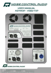
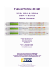
LMS-A6
LOUDSPEAKER
MANAGEMENT SYSTEM
USER’S MANUAL
Turbosound Ltd.
Star Road, Partridge Green
West Sussex RH13 8RY England
Tel: +44 (0)1403 711447 Fax: +44 (0)1403 710155
web: www.turbosound.com
user manual
LMS-A6
CONTENTS
Important Safety Information ................................................................................................................. 3
Thanks...................................................................................................................................................... 4
Unpacking the LMS-A6 ........................................................................................................................... 4
Introduction ............................................................................................................................................. 5
Features ................................................................................................................................................... 5
Front Panel Functions ............................................................................................................................. 6
Rear Panel Functions............................................................................................................................... 7
Setting up and operating the LMS-A6.................................................................................................... 8
Internal factory set parameters .......................................................................................................... 8
Crossover frequencies and slopes ..................................................................................................... 8
Band Gain ............................................................................................................................................ 8
Equalisation ......................................................................................................................................... 8
Mains Supply Voltage ......................................................................................................................... 8
Connecting inputs and outputs .......................................................................................................... 9
The Power Supply section ...................................................................................................................... 9
Power On Standby Mode.................................................................................................................. 10
Remote standby..................................................................................................................................... 10
Connecting Remote Standby............................................................................................................ 10
Remote Standby Cancel.................................................................................................................... 10
Mono Band 1 ..................................................................................................................................... 10
Level Trims ........................................................................................................................................ 11
Phase Adjustment ............................................................................................................................. 11
Limiter setting and operation ............................................................................................................... 11
Limiter Threshold setting ................................................................................................................. 11
Limiter Cancel.................................................................................................................................... 12
Output Level and Limiter Meter ....................................................................................................... 12
Band Mutes........................................................................................................................................ 12
Technical specifications ........................................................................................................................ 13
Warranty ................................................................................................................................................ 14
LMS-A6 user manual
Page 2
user manual
LMS-A6
An example of this equipment has been tested and found to comply with the
following European and international Standards for Electromagnetic
Compatibility and Electrical Safety:
Radiated Emissions (EU):
EN55013-1 (1996)
RF Immunity (EU):
EN55103-2 (1996) RF Immunity, ESD,
Burst Transient, Surge, Dips &Dwels
Electrical Safety (EU):
EN60065 (1993)
IMPORTANT SAFETY INFORMATION
Do not remove Covers. There are no user serviceable parts inside, please refer servicing to
qualified service personnel. This equipment must be earthed.
CAUTION
RISK OF ELECTRIC SHOCK
DO NOT OPEN
DO NOT EXPOSE TO RAIN OR MOISTURE
ATTENTION
RISQUE DE CHOC ELECTRIQUE
NE PAS ENLEVER
NE PAS EXPOSER A LA PLUIE NI A L’HUMITE
It should not be necessary to remove any protective earth or signal cable shield connections.
Do not defeat the purpose of the polarized or grounding-type plug. A polarized plug has two
blades with one wider than the other. A grounding type plug has two blades and a third grounding
prong. The wider blade and the third prong are provided for your safety. When the provided plug
does not fit into your outlet, consult an electrician for replacement of the obsolete outlet.
Only use this equipment with an appropriate mains cord.
In the USA the cord should comply with the requirements contained in the Standard for Cord Sets
and Power Supply Cords, UL 817, be marked VW-1, and have an ampacity rating not less than the
marked rating of the apparatus.
LMS-A6 user manual
Page 3
user manual
LMS-A6
THANKS
Thank you for choosing the TURBOSOUND LMS-A6 for your application. Please spare a little time
to digest the contents of this manual, so that you obtain the best possible performance from this
unit.
All TURBOSOUND products are carefully engineered for world class performance and reliability.
If you would like further information about this or any other TURBOSOUND product, please
contact us.
We look forward to helping you in the near future.
UNPACKING THE LMS-A6
After unpacking the unit please check carefully for damage. If damage is found, please notify the
carrier concerned at once. You, the consignee, must instigate any claim. Please retain all
packaging in case of future re-shipment.
LMS-A6 user manual
Page 4
user manual
LMS-A6
INTRODUCTION
The LMS-A6 is a versatile two input, six output, analogue loudspeaker management system in a
1U rack mount package that is designed for maximum sonic performance. It combines crossover
and limiter functions and is uniquely configurable to custom requirements.
The LMS-A6 can be configured for the following modes of operation: stereo 3-way, stereo 2-way,
mono 4-way, plus mono 2-way. The standard filter provided for the LMS-A6 is a Linkwitz Riley
response based on two second order Butterworth circuits in series. The response is 24dB/octave
slope with a corner frequency where the output of the filter is 6dB down from its pass band level.
The use of these filter realisations has been well documented and provides the best possible
phase and amplitude response for driving loudspeaker systems.
Active crossovers versus passive crossovers
Passive crossovers divide the frequency spectrum after the signal has been raised to high power
levels. They are generally bulky, heavy and inefficient. Active crossovers utilise IC’s and
transistors, and divide the frequency spectrum at line level immediately ahead of the amplifiers.
An active crossover does the same job as a passive crossover, but with more precision, flexibility,
efficiency and quality. Crossover frequencies can be readily altered to suit different driver
combinations, the level balance between two or three frequency bands can easily be trimmed, and
line driving, system muting, signal summing, driver equalisation and phase adjustment facilities
can all be incorporated into active crossovers.
FEATURES
•
Maximum sonic performance: advanced circuit design for exceptional dynamic range and
sonic quality.
•
Interchangeable frequency programming cards: set the required crossover frequency and
slope of your loudspeaker system. These are supplied when the unit is shipped from the
factory.
•
A flexible 2 input, 6 output multi-mode format featuring a choice of stereo 3-way, stereo 2way, mono 4-way plus mono 2-way crossover modes with limiters.
•
High performance limiters are provided, one for each output band. Limiter threshold is set by
means of 10-position switches located behind a security panel on the rear of the unit.
•
Electronically balanced inputs and outputs: ensures a high level of rejection for common
mode rejection signals and gives a professional connection to external equipment.
LMS-A6 user manual
Page 5
user manual
LMS-A6
FRONT PANEL FUNCTIONS
24
5
7
11 12
8
POL
13
1.
6
9
10
13
Mono Band 1 – sums the Left and Right Band signals together (up position) and feeds them in
mono to both Band 1 outputs.
2.
Limiter cancel – disables all limiter functions and causes the LIMITER CANCEL LED to light.
3.
Power Standby switch – determines the power-up mode: in the up (cancel) position the unit
automatically switches out of mute after six seconds; in the down position the unit remains in
standby mode with all outputs muted.
4.
Remote Standby cancel – enables (down position) or disables (up position) the REMOTE
STANDBY function. Inoperable if the remote stanby function has not been wired up.
5.
Phase adjustment – variable adjustment between 0° and 180°.
6.
Gain trim – allows the band 1 gains and band 3 gains to be adjusted to match band 2 where
speaker/amplifier sensititvities vary for each band.
7.
Polarity – reverses the polarity of the selected frequency band.
8.
Mute LED – indicates mute staus of the selected channel.
9.
Mute key – one latching mute switch per output channel. Press to mute; press again to unmute.
10. Output meters – LED ladder displays headroom before limiting occurs. The lower four green
LEDs indicate –24dB, -12dB, -6dB and –1dB respectively, with the orange ‘LIM’ LED set at the
limiter threshold for that channel. The top, red LED indicates 4dB of limiting.
11. Power – green LED indicates that power is applied to the unit.
12. Standy Mute – red LED indicates when the standby mute mode is set.
13. Limiter Cancel – indicates when the limiter cancel mode is set.
LMS-A6 user manual
Page 6
user manual
LMS-A6
REAR PANEL FUNCTIONS
AC
50/60Hz 40VA
S.No 10 - 1001 - A
230V
ALWAYS USE SAFETY GROUND
NO USER SERVICEABLE PARTS INSIDE
1
1.
2
3
4
5
6
7
Mains Power - Connected via a standard IEC socket. A compatible power cord is supplied with
the unit.
2.
Power Switch.
Switch
3.
Mains Fuse - Located in a finger-proof fuseholder adjacent to the mains inlet. Always replace
this fuse with the correct type as shown on the rear panel legend.
4.
Remote Standby connector – for remote switch connection.
5.
XLR Outputs - 3 pin male XLR connectors are provided for each audio output. All terminations
are fully balanced, pin 2 Hot, pin 3 Cold and pin 1 Screen (shield).
6.
Limiter threshold – sets limiter threshold for each output band.
7.
XLR Inputs – 3 pin female XLR connectors are provided for each audio input. All terminations
are fully balanced, pin 2 Hot, pin 3 Cold and pin 1 Screen (shield).
LMS-A6 user manual
Page 7
user manual
LMS-A6
SETTING UP AND OPERATING THE LMS-A6
This section describes the steps and checks to be taken when setting up the unit for the first time,
and the operation of all the controls and indicators. Some of the custom operating parameters will
have been set internally when unit left the factory. These are described in this section and you
must check that these are appropriate for your system.
Internal factory set parameters
Check the supplied documentation to ensure these parameters are correct for the particular
system you are setting up. Incorrect settings can damage the loudspeakers, especially the more
delicate H.F. unit. If any internal settings are wrong for your system contact your Turbosound
Dealer about obtaining the correct custom plug-in modules.
Crossover frequencies and slopes
There are two stereo frequency programming cards located internally. Card 1 handles band 1
information and card 2 band 2 & band 3 information. The crossover frequencies and slopes will
have been specified when the unit was purchased. The limiter time constants and the band edge
phase adjustment time constants will automatically have been optimised for the corner
frequencies. The relevant frequency, slope and response type is recorded on a label attached to
the respective cards and also on a label attached to the right hand side panel of your unit.
If in the future your unit is to be used to drive loudspeaker systems other than that for which it
was originally configured, then replacement frequency programming cards can easily be fitted.
Band Gain
The gain of each band is normally set to unity, but for systems where the sensitivity of the
Amplifier/Speaker combinations for each Band are different, the gain of each band may have been
set to compensate. This allows the Level Trim controls to be nominally set to centre.
Equalisation
Either static or dynamic equalisation may have been installed on an optional internal module.
Mains Supply Voltage
The unit will have been set for either 115V AC or 230V AC operation as indicated by the label on
the rear of the unit.
LMS-A6 user manual
Page 8
user manual
LMS-A6
Connecting inputs and outputs
This section describes how to connect signals to the LMS-A6 loudspeaker management system.
The signal inputs are industry standard female XLR connectors and are wired as follows:Pin 1 = GROUND or COMMON
Pin 2 = HOT or (+) or In-phase
Pin 3 = COLD or (-) or Out of phase
The electronically balanced inputs will take a maximum level of +20dBu at 10k ohm impedance.
They will accept either balanced or unbalanced signals.
The signal outputs are industry standard male XLR connectors and are wired as follows:Pin 1 = GROUND or COMMON
Pin 2 = HOT or (+) or In-phase
Pin 3 = COLD or (-) or Out of phase
The output impedance is less than 100 ohms and the maximum signal level is +20dB. The
electronically balanced output stage will drive either balanced or unbalanced loads.
THE POWER SUPPLY SECTION
The power supply section includes an IEC connector, ON/OFF switch and an AC fuse.
Check that the voltage label corresponds with your local mains supply and that the correct AC fuse
is fitted. If it does not, contact your Turbosound Dealer for instructions on setting the LMS-A6 to
the correct voltage.
Connecting to the wrong voltage may damage the unit.
The unit must be switched OFF before inserting or removing the mains cord.
When the system is powered and turned on, the green POWER LED on the front panel lights. If the
LED fails to light when power is applied and switched on check and, if necessary, replace the AC
fuse. If this does not solve the problem then an internal fuse may have blown. This indicates that
the unit has a fault and you should contact your Turbosound Dealer for further advice.
LMS-A6 user manual
Page 9
user manual
LMS-A6
Power On Standby Mode
When power is first switched on the LMS-A6 enters STANDBY mode. In this mode all outputs are
muted to suppress any noise or transients while the circuitry settles down.
The POWER STDBY switch determines how the unit will behave after power is applied.:
Switch down: The unit will stay in standby mode. All outputs will stay muted and the red
STANDBY MUTE LED will light.
The standby mode is cancelled by pressing any MUTE switch, or momentarily operating the
REMOTE STANDBY switch.
Switch up (CANCEL). The unit will remain muted for about six seconds and then automatically
come out of standby mode.
In either case the normal band MUTEs will remain as they were when the unit was last used.
REMOTE STANDBY
Connecting Remote Standby
A two wire connection may be made between this connector and a single pole switch located at
your mixing console, or any other operating position. When this switch is open, the unit functions
normally and the outputs follow the MUTE switches on the front panel. When the REMOTE switch
is closed all outputs are muted and the red REMOTE STANDBY LED lights.
The switch should be floating and isolated from external grounds. No damage will occur if the
wires short to ground, but proper operation is not guaranteed.
Remote Standby Cancel
This switch enables or disables the REMOTE STANDBY function. Putting this switch up (CANCEL)
will disable the remote function. You may wish to cancel the remote switch if it has been left in
standby mode but you wish to regain local control. If the Remote Standby function has not been
wired up this switch does nothing and may be set to either position.
Mono Band 1
How loud a system of a given power will go is usually limited by the lower frequencies. This is
because low frequency signals require higher voltage swings, hence more power, than high
frequencies. In order to make best use of the headroom available from the amplifiers and low
frequency loudspeakers it is common practice to send all low frequencies to both channels in a
stereo system. This has little impact on the stereo image in most situations.
LMS-A6 user manual
Page 10
user manual
LMS-A6
When this switch is up (on) the Left and Right Band 1 signals are summed together and fed in
mono to both Band 1 outputs.
When the switch is down the Left and Right Band 1 signals remain independent from each other.
Level Trims
Band 1 and Band 3 have independent gain trims for fine adjustment of the system frequency
response. If the internal preset band gains have been specified correctly these controls will
nominally all be set central at 0dB. The +/-6dB range should be more than sufficient to balance
your system in any realistic situation. Band 2 gain is taken as the reference level, and the Band 1
and Band 3 controls will be adjusted for correct spectral balance.
Phase Adjustment
In a theoretically ideal speaker design the drive units for adjacent bands would be in perfect
alignment and their signals would combine to give perfect summation at the crossover point.
However, realistically this seldom occurs and shifting the phase of one of the signals in the
crossover region will improve the summing, and therefore the frequency response of the system.
Each phase control gives nearly 180 degrees of adjustment. Used in combination with the POL
Switch we can achieve continuous adjustment over a full 360 degrees.
There may be some interaction between the phase controls in each channel, especially if the MID
Band, Band 2 is fairly narrow, so it is advisable to further fine tune the phase by repeating the
above process a second time.
LIMITER SETTING AND OPERATION
The limiters should be set to a level that affords protection to the speaker drive units. The time
constants for the limiters are set internally and are preset to be optimum for each frequency band
being protected.
Limiter Threshold setting
The limiter threshold switches are located behind a security cover on the rear of the unit. Each
Band has an independent 10 position switch to accurately set the threshold. The switches are
calibrated in 1dB steps from +1dB (Pos0) to +10dB (Pos9)
In a high powered system where the amplifier output power is below or equal to the rating of the
speakers the limiter thresholds will nominally be set to 1dB below the clipping level of the
amplifier. This prevents severe clipping from driving the cones with square waves but does not
LMS-A6 user manual
Page 11
user manual
LMS-A6
restrict the full undistorted output of the amplifiers. Note that the actual output power available
often depends on the mains supply voltage, which may ‘sag’ during heavy performances.
In a system where the amplifiers are capable of exceeding the ratings of the speakers, set the
threshold to a level appropriate to the speakers and NOT the clipping point of the amplifier. This is
normally achieved by feeding the system with pink noise at the maximum level required and then
turning down each limiter threshold switch until the yellow LIM LED is just flashing.
Limiter Cancel
When up (CANCEL), this switch will disable all limiters and the yellow LIMITER CANCEL LED will
light. It is normally only used when setting up and calibrating - or trouble shooting - the system.
When the limiters are cancelled the output meters will continue to operate normally up to the
limiter threshold.
Output Level and Limiter Meter
The lower four green LEDs show the signal level in dB relative to the limiter threshold. i.e. they
always show the signal headroom that is available before the limiters will start operating. The
yellow LIM LED lights when the threshold has been reached and the limiter is operating. The top
red LED lights when the input signal is causing 4dB or more limiting to occur. If during use the +4
LEDS are on for more than occasional brief flashes the input signal is too hot and should be
turned down at the mixing console to reduce distortion.
Band Mutes
Each output has an independent MUTE Switch and red MUTE LED. These are latching switches
which will retain their settings even when power is turned off and on again.
Note that the MUTE LED will always follow the position of the MUTE switch regardless of the
status of the standby mute. If the expected output signal appears to be muted but the MUTE LED
is not lit then check the STANDBY MUTE LED
LMS-A6 user manual
Page 12
user manual
LMS-A6
TECHNICAL SPECIFICATIONS
Inputs
Two electronically balanced
Impedance
> 10k ohms
CMRR
>65dB 50Hz - 10kHz
Outputs
Six electronically balanced
Source Imp
< 60ohms
Min. Load
600ohms
Max. Level
+20dBm into 600 ohm load
Frequency Response
±0.5dB 20Hz - 20kHz
Dynamic Range
>110dB 20Hz -20kHz. Unwtd
Distortion
< 0.02% @ 1kHz, +18dBm
Maximum Delay
650 mS. (Increment 2..6 µS)
Output gain
adjustable +6dB to -6dB
High and Lowpass Filters
Filters
1 of each per output
Subsonic filter
user specified up to 24dB/octave
Low mid filter
user specified up to 24dB/octave
High mid filter
user specified up to 24dB/octave
Ultra sonic filter
user specified up to 12dB/octave
Response
Bessel / Butterworth 12/18/24dB /oct and Linkwitz-Riley 24dB /oct
Limiters
Threshold
+1dB to -10dB in 1dB steps
Output meters
6 x 6 point, -24dB to +4dB into limit
Connectors
Inputs
3 pin female XLR
Outputs
3 pin male XLR.
Power
3 pin IEC
Power
85 to 130V or 190 to 260V (set internally) @ 50/60Hz
Fuses
230V T200mA, 115V T1250mA
Consumption
25 VA
Net weight
3.9kg (8.6lbs)
Size
1.75"(1U) x 19" x 9.9" (44mm x 482mm x 252mm) excl. connectors.
Due to continuing product improvement the above specifications are subject to change.
LMS-A6 user manual
Page 13
user manual
LMS-A6
WARRANTY
This product is warranted against defects in components and workmanship only, for a period of
one year from the date of shipment to the end user. During the warranty period, TURBOSOUND
will, at its discretion, either repair or replace products which prove to be defective, provided that
the product is returned, shipping prepaid, to an authorised TURBOSOUND service facility.
Defects caused by unauthorised modifications, misuse, negligence, act of God or accident, or any
use of this product that is not in accordance with the instructions provided by TURBOSOUND, are
not covered by this warranty.
This warranty is exclusive and no other warranty is expressed or implied. TURBOSOUND is not
liable for consequential damages.
LMS-A6 user manual
Page 14
Turbosound Ltd
Star Road, Partridge Green
West Sussex RH13 8RY England
Tel:+44 (0)1403 711447 Fax: +44 (0)1403 710155
web: www.turbosound.com