1
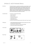
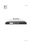
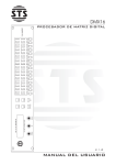
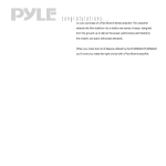
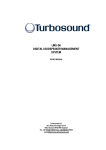
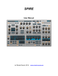
DP-II Series
LOUDSPEAKER MANAGEMENT
User Manual
Introduction
1. Read these instructions.
2. Keep these instructions.
3. Heed all warnings.
4. Follow all instructions.
5. Do not use this apparatus near water.
6. Clean only with dry cloth.
7. Do not block any ventilation openings. Install in accordance with the manufacture’s instructions.
8. Do not install near any heat sources such as radiators, heat registers, stoves, or other apparatus (including amplifiers)
that produce heat.
9. Do not defeat the safety purpose of the polarized or grounding-type plug. A polarized plug has two blades with one
wider than the other. A grounding-type plug has two blades and a third grounding prong. The wide blade or the third
prong are provided for your safety. If the provided plug does not fit into your outlet, consult an electrician for
replacement of the obsolete outlet.
10. Protect the power cord from being walked on or pinched particularly at plugs, convenience receptacles, and the
point where they exit from the apparatus.
11. Use only attachments/accessories specified by the manufacturer.
12. Use only with the cart, stand, tripod, bracket, or table specified by the manufacturer, or sold with the apparatus.
When a cart is used, use caution when moving the cart/apparatus combination to avoid injury from tip-over.
13. Unplug this apparatus during lighting storms or when unused for long periods of time.
14. Refer all servicing to qualified service personal. Sevicing is required when the apparatus has been damaged in any
way, such as power supply cord or plug is damaged, liquid has been spilled or objects have fallen into the apparatus,
the apparatus has been exposed to rain or moisture, does not operate normally, or has been dropped.
15. The apparatus shall be connected to a MAINS socket outlet with a protective earthing connection.
16. Where the MAINS plug or an appliance coupler is used as the disconnect device, the disconnect device shall remain
readily operable.
The symbol, wherever is appears, alerts you to the presense of uninsulated dangerous voltage inside the
enclosure-voltage that may be sufficient to constitute a risk of shock.
The symbol, wherever is appears, alerts you to important operating and maintenance instructions
in the accompanying literature. Please read the manual.
To reduce the risk of electric shock, do not remove the top cover (or the rear section). No user serviceable
parts inside. Refer servicing to qualified personnel.
To reduce the risk of fire to electric shock, do not expose this appliance to rain and moisture. The apparatus
shall not be exposed to dripping or splashing liquids and no objects filled with liquids, such as vases, shall be
placed on the apparatus.
These service instructions are for use by qualified service personal only.
To reduce the risk of electric shock do not perform any servicing other than that contained in the operation
instructions. Repairs have to be performed by qualified service personal.
CAUTION
RISK OF ELECTRIC SHOCK
DO NOT OPEN
DO NOT EXPOSE TO RAIN, MOISTURE,
DRIPPING OR SPLASHING
Introduction
The DP-II Series are powerful DSP based loudspeaker processors, ideally suited for install application, where they
combine the functions of a multitude of conventional products in a compact 1U unit with extensive remote control
capabilities. To achieve this, the DP Series devices have two inputs, three inputs, and four inputs and up to eight
outputs.
Base crossover modes:
6 Outputs have 2x2 way, 2x3 way, 4+2 way, 5+1 way and 6 way.
4 Outputs have 2x2 way, 3+1 way, 4 way and 2 MonoSub.
Units also offer “Source” for free assign signal, which allows completely flexible routing of any output from any
combination of inputs.
Each input has a gain control, multi-type filters. Filter types included parametric equalisation, high & low shelving.
Each output has a gain control, variable delay line, highpass and lowpass crossover filters, seven band multi-type filters,
polarity, input signal source, a limiter. The crossover filters offer slopes of up to 48dB/Octave.
Security lock-out is avaiable for each parts.
Supply external device remote controls.
Remote port is RS232 .
Front Panel
5
3
4
1
2
1. LCD Sreeen: Show, the name of last recalled memory on the bottom line of the screen, and current device model
name on the top line. Also used to show all parameters as they are edited, and all menu selections.
2. BACK/ NEXT: Moves backwards or forward through list of parameters.
MENU: Activates the main menu.
BYPASS: Bypass filter.
QUIT: Quit key.
ENTER: Enter key.
3. Rotary Encoders: Three velocity encoders adjust parameters.
4. MUTE: These buttons illuminate when pressed and mute audio for that channel.
(Press and Hold 3 seconds) Access current channel parameters.
5. Meters: Input and Output meters show dB from clipping point. Red CLIP LED show signal overflow, Yellow LED
show signal near -3dB.
Rear Panel
~
1
2
4
3
1. Power Switch: turns the device’s mains supply off and on.
2. RS232: RS232 standard via a 9 pin D-type connector, for connection to PC.
3. Audio Inputs: 3 pin XLR sockets are provided for each channel. All are fully balanced, pin 2 hot, 3 cold, 1 screen.
4. Audio Outputs: 3 pin XLR sockets are provided for each channel. All are fully balanced, pin 2 hot, 3 cold, 1 screen.
Diagram of input channels
MUTE
PEQ
GAIN
INPUT
A
Diagram of output channels
HPF
LPF
PEQ
DELAY
GAIN
LIMITER
MUTE
OUTPUT
1
Input Gain
The range of the control over the input gain is -40dB to +6dB in 0.1dB steps.
InputA
Gain
Gain = + 0 . 0dB
Gain
Input Parametric EQ
Pressing BYPASS will bypass the All bands EQ.
InputA
All-EQ
Bypass = Off
Bypass
The range of frequency is 20Hz to 20kHz in 1/36 Octave. The range of Q is 0.4 to 128. The range of gain is -30dB to
+15dB in 0.1dB steps.
InputA
PEQ : 01
1k00Hz Q=3 . 0 +0 . 0dB
Frequency
‘Q’
Gain
Frequency
‘Q’
Gain
Frequency
‘Q’
Gain
Pressing BYPASS will bypass the current band EQ.
InputA
PEQ : 01
1k00Hz Q=3 . 0 +0 . 0dB
Bypass
While filter was in BYPASS ON, Changing the filter type is achieved by pressing ENTER.
( LoShelf )
( HiShelf )
InputA
LSF : 01
1k00Hz Q= . 71 +0 . 0dB
InputA
HSF : 01
1k00Hz Q= . 71 +0 . 0dB
Input Link
Set link value for channel, while modify parameters, the channel of have same link value will modify together.
InputA
Link
Link = None
Link
Output Gain
The range of the control over the input gain is -40dB to +15dB in 0.1dB steps.
Out1 Output1
Gain
Output Gain = + 0 . 0dB
Gain
Output Polarity
The polarity (or phase) of each output may be switched individually.
Out1 Output1 Polarity
Polarity = [+]
- or +
Output Delay
The maximum avaiable delay depend on different devices.
Out1 Output1 Delay
Delay = 0 . 000mS
x10mS
3.43 m
x1mS
343mm
x10uS
4mm
Output Highpass/Lowpass Filter
The highpass/lowpass filter on each output has a frequency range of 20Hz to 20kHz in 1/36 Octave steps.
Crossover slope can be 6dB, 12dB, 18dB, 24dB, 36dB and 48dB/Octave.
Filter type can be Butterworth, Linkwitz-Riley, Bessel.
Out1 Output1 HPF
20 . 5Hz Butwrth 24dB
Frequency Slope
Out1 Output1 LPF
20k2Hz Lnk/Ril 48dB
Frequency Slope
Output Parametric EQ
Pressing BYPASS will bypass the All bands EQ.
Out1 Output1 All-EQ
Bypass = Off
Bypass
The range of frequency is 20Hz to 20kHz in 1/36 Octave. The range of Q is 0.4 to 128. The range of gain is
-30dB to +15dB in 0.1dB steps.
Out1 Output1 PEQ : 01
1k00Hz Q=3 . 0 +0 . 0dB
Frequency
‘Q’
Gain
Frequency
‘Q’
Gain
Frequency
‘Q’
Gain
Pressing BYPASS will bypass the current band EQ.
Out1 Output1 PEQ : 01
1k00Hz Q=3 . 0 +0 . 0dB
Bypass
While filter was in BYPASS ON, Changing the filter type is achieved by pressing ENTER.
( LoShelf )
( HiShelf )
Out1 Output1 LSF : 01
1k00Hz Q= . 71 +0 . 0dB
Out1 Output1 HSF : 01
1k00Hz Q= . 71 +0 . 0dB
Output Limiter
The limiter on each output has adjustable attack time, release time and threshold.
The range of attack time 0.3 to 90mS, the range of release time 0.1 to 2.0 second, the range of threshold -10dB to
+15dB in 0.1dB steps.
Out1 Output1 Limiter
A:1 . 4mS R:2 . 0S +15dB
Attack
Release Threshold
Output Channel Name
For edit channel name by pressing ENTER. Cursor will blink on first character position.
Turn rotary encoder and modify character, move cursor position by pressing BACK or NEXT.
Pressing ENTER again for confirm and store channel name.
Out1 Output1 Name
Name = Output1
Char
Source
The source on each output, can assign signal rounting from input channel, create free Xover combination.
Out1 Output1
Source =
Source
A
Source
Pressing ENTER will switch each input channel mix gain.
Out1 Output1 InputA
Mix Gain = +0 . 0dB
MixGain
Output Link
Set link value for channel, while modify parameters, the channel of have same link value will modify together.
Out1 Output1 Link
Link = None
Link
Menu System
Pressing MENU will enter menu system. Pressing ENTER will enter sub-menu.
MAIN MENU :......
Program Sub - Menu
MAIN MENU : . . . . . .
CopyTools Sub - Menu
MAIN MENU :..... .
Interface Sub - Menu
MAIN MENU : . . . . . .
System Sub - Menu
MAIN MENU : . . . . . .
Security Sub - Menu
Program Sub-menu
Load Factory Program.
Load User Program.
Design a Xover.
Save User Program.
Delete User Program.
PROGRAM MENU :...
Load User Program
Pressing ENTER will enter Load User Program sub-menu.
Load User Program
01 : 2x3 Way Xover
Turn rotary encoder to change program index,
Pressing ENTER
[ ENTER ] for Recall .
01 : 2x3 Way Xover
Pressing ENTER for confirm and load program.
Loading New Program
01 : 2x3 Way Xover
PROGRAM MENU :...
Design a Xover
Design a Xover
Type : 2x2 WAY XOVER
New Xover
[ ENTER ] to Confirm
About Xover mode details, see Appendix I.
Pressing ENTER will enter Design a Xover sub-menu.
Turn rotary encoder to change Xover mode,
Pressing ENTER
Pressing ENTER for confirm and change Xover mode.
PROGRAM MENU :...
Save User Program
Save User Program
01 : 2x3 Way Xover ?
[ ENTER ] to Overwrite
01 : 2x3 Way Xover ?
Set Program Name
01 : 2x3 Way Xover ?
[ ENTER ] to Save
01 : 2x3 Way Xover ?
Pressing ENTER will enter Save User Program sub-menu.
Turn rotary encoder to change program index,
Pressing ENTER.
Pressing ENTER for confirm and overwrite program.
Pressing QUIT for exit.
Program name length is 16 character.
Turn rotary encoder and modify character, move cursor position
by pressing BACK or NEXT.
Pressing ENTER again for confirm and store program name.
Pressing QUIT for exit.
Pressing ENTER for confirm and Save program.
Saving to Memory
01 : 2x3 Way Xover ?
PROGRAM MENU :...
Delete User Program
Pressing ENTER will enter Delete User Program sub-menu.
Delete User Program
01 : 2x3 Way Xover
Turn rotary encoder to change program index,
Pressing ENTER.
[ ENTER ] to Delete .
01 : 2x3 Way Xover
Pressing ENTER for confirm and delete program.
Deleting Memory ...
01 : 2x3 Way Xover
CopyTools Sub-menu
Copy Input Section
Copy Output Section
COPYTOOLS MENU :...
Copy Input Section
Copy Input Section
Source : A Target : B
On Copy Input Section screen, Turn rotary “FREQ”encoder change source channel,
Turn rotary “Q” encoder change target channel.
Pressing ENTER to confirm and copy intput channel parameters.
COPYTOOLS MENU :.. .
Copy Output Section
Copy Output Section
Source : 1 Target : 2
On Copy Output Section screen, Turn rotary “FREQ”encoder change source channel,
Turn rotary “Q” encoder changetarget channel.
Pressing ENTER to confirm and copy output channel parameters.
System Sub-menu
SYSTEM MENU :......
LCD Contrast
SYSTEM MENU :......
LED Brightness
SYSTEM MENU :......
Wake - up Time
SYSTEM MENU :......
Filter Q or BW
Turn rotary encoder to change LCD contrast,
Pressing ENTER to confirm and save.
Turn rotary encoder to change LED brightness,
Pressing ENTER to confirm and save.
Device startup wake up time.
Mute Hold, set to keep mutes on when powered up.
0 secs......60 secs, set wait time before the audio fades in.
Turn rotary encoder to change parameter,
Pressing ENTER to confirm and save.
Select filter Q or Bandwidth display unit.
Turn rotary encoder to change parameter,
Pressing ENTER to confirm and save.
SYSTEM MENU :......
DelayTime / Distance
Select delay time or distance.
Turn rotary encoder to change parameter,
Pressing ENTER to confirm and save.
SYSTEM MENU :......
Output LED Meter
Select output meter indicate style.
output Level or attenute on limiter.
Turn rotary encoder to change parameter,
Pressing ENTER to confirm and save.
SYSTEM MENU :......
Load Program Option
SYSTEM MENU :......
Device Name Title
[ ENTER ] to Editing
Tit : Speaker Processor
Set Device NameTitle
Tit : Speaker Processor
[ ENTER ] to Store
Tit : Speaker Processor
Select load program option.
AutoMute: Force all output mute on after loading program.
LoadMute: Load output MUTE status in program stored.
Turn rotary encoder to change parameter,
Pressing ENTER to confirm and save.
Change device title name on LCD screen top line.
Pressing ENTER to edit.
Device name length is 16 character.
Turn encoder and modify character.
move cursor position by pressing BACK or NEXT.
Pressing ENTER for confirm.
Pressing QUIT for exit.
Pressing ENTER again for confirm and store.
Interface Sub-menu
INTERFACE MENU :....
Interface Setup
Interface Setup
Master Source: RS232
Select communication port: RS232.
INTERFACE MENU :....
Protocol Setup
Protocol Setup
Select: PCsw Ctrl
Protocol Setup
Select: ESRP Ctrl
Select control protocol.
PCsw: select PC control.
ESRP: select external simple control device.
Security Sub-menu
Pressing ENTER will enter Security sub-menu.
Lock status setting:
No Lock: without lock out.
Control: cannot change.
Display: cannot view.
Xover Only
Xover + Trim
Xover + Trim
+ Mute
Changes Only
Input Gain
No Lock
No Lock
No Lock
Control
Display
Control
Display
Input PEQs
No Lock
No Lock
No Lock
Control
Display
Control
Display
Input Links
No Lock
No Lock
No Lock
Control
Display
Control
Display
Output Gain
No Lock
Display
Display
Control
Display
Control
Display
Output Delay
Display
Display
Display
Control
Display
Control
Display
Output PEQs
Display
Display
Display
Control
Display
Control
Display
HPFs & LPFs
Display
Display
Display
Control
Display
Control
Display
Output Links
Display
Display
Display
Control
Display
Control
Display
Output Phase
Display
Display
Display
Control
Display
Control
Display
Limiters
Display
Display
Display
Control
Display
Control
Display
Matrix Gains
Display
Display
Display
Control
Display
Control
Display
Input Mutes
No Lock
No Lock
No Lock
No Lock
No Lock
Control
Control
Output Mutes
No Lock
No Lock
Control
No Lock
No Lock
Control
Control
Output Name
Control
Control
Control
Control
Control
Control
Control
Menu System
No Lock
No Lock
No Lock
No Lock
No Lock
No Lock
Control
Memory Store
No Lock
No Lock
No Lock
No Lock
No Lock
No Lock
Control
Memory Load
No Lock
No Lock
No Lock
No Lock
No Lock
No Lock
Control
File Operation
No Lock
No Lock
No Lock
No Lock
No Lock
No Lock
Control
Changes + View Changes + Mutes
In “User Specific” setting, you can free set up lock status depend on each function part.
Enter Password
[******]
Enter Password
[******]
Confirm Password
[******]
UnLocking Unit
[******]
Locking Unit
[******]
Speaker Processor
2 X 3 Way Xover
Pressing ENTER will enter password.
Turn rotary encoder and modify character, move cursor position by pressing BACK or NEXT.
Pressing ENTER for enter password again.
while twice time password match, system will lock unit.
EVERYTHING
Specifications
Inputs: 2 electronically balanced.
Impedance: > 10k ohms.
CMRR: > 75dB 50Hz ~ 10kHz.
Outputs: 4/6 electronically balanced.
Source Imp: < 60ohms
Min. Load: 600ohm
Max. Level: +15dBm
Digital Audio Sample Rate: 96kHz
Frequency Response: +/- 0.5dB, 20Hz ~ 20kHz
Distortion: < 0.02% @1kHz, +15dBm
ADC Dynamic Range: > 110dB, 20Hz ~ 20kHz (A-Weight)
DAC Dynamic Range: > 110dB, 20Hz ~ 20kHz (A-Weight)
Propagation Delay: 0.21mS (DP240-II / DP260-II)
Delay: 10mS(Output)
Min Step Size: 0.010mS(4mm)
Input Gain: -40dB to +6dB in 0.1dB steps
Output Gain: -40dB to +15dB in 0.1dB steps
Multi-Type Filters
10 per Input, 7 per Output.
Freq. Range: 20Hz ~ 20kHz, 1/36 Octave steps.
Filter Q/BW: 0.4 to 128.
Filter Type: parametric equaliser
HiShelf, LoShelf
High and Lowpass Filters
Freq. Range: 20Hz ~ 20kHz, 1/36 Octave steps.
Slope: 6/12/18/24/36/48 dB/Octave.
Type: Butterworth, Linkwitz-Riley, Bessel.
Limiters
Threshold: -10 ~ +15dB, 1dB steps.
Attack time: 0.3 ~ 90mS.
Release time: 0.1 ~ 2.0 second.
Display: 2x20 Character LCD
Connectors
Inputs: 3 pin female XLR
Output: 3 pin male XLR
RS232: 9 pin DEE connector
Power: 3 pin IEC
Power Voltage: ~220V @50/60Hz
Power Consumption: < 15 watts
Weight: 2.7kg. Net (4.0kg. Shipping)
Size: 1.75”(1U) x 19” x 7.7” (44 x 482 x 197 mm)
Appendix I - Crossover Configurations
2x2 Way ( DP260-II )
2x3 Way ( DP260-II )
INPUT
OUTPUT
INPUT
OUTPUT
A
1
A
1
OUTPUT
OUTPUT
2
2
INPUT
OUTPUT
OUTPUT
B
3
3
OUTPUT
INPUT
OUTPUT
4
B
4
OUTPUT
OUTPUT
5
5
OUTPUT
OUTPUT
6
6
4+2 Way ( DP260-II )
INPUT
A
5+1 Way ( DP260-II )
OUTPUT
1
INPUT
OUTPUT
A
1
OUTPUT
OUTPUT
2
2
OUTPUT
OUTPUT
3
3
OUTPUT
OUTPUT
4
4
INPUT
OUTPUT
B
5
OUTPUT
6
6 Way ( DP260-II )
INPUT
OUTPUT
A
1
OUTPUT
2
OUTPUT
3
OUTPUT
4
OUTPUT
5
OUTPUT
6
OUTPUT
5
INPUT
OUTPUT
B
6
2x2 Way ( DP240-II )
3+1 Way ( DP240-II )
INPUT
OUTPUT
INPUT
OUTPUT
A
1
A
1
OUTPUT
OUTPUT
2
2
INPUT
OUTPUT
OUTPUT
B
3
3
OUTPUT
INPUT
OUTPUT
4
B
4
4 Way ( DP240-II )
2 Mono Sub ( DP240-II )
INPUT
OUTPUT
INPUT
OUTPUT
A
1
A
1
OUTPUT
OUTPUT
2
2
OUTPUT
OUTPUT
3
3
OUTPUT
INPUT
OUTPUT
4
B
4
Appendix II - Different Device Comparision
Model
DP260-II
Channel
DP240-II
2
Delay
Filter
Channel
10
6
4
Filter
7
Delay
10mS