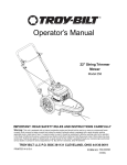
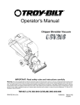
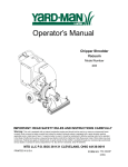
1
Operator’s Manual
Self Propelled
Yard Vacuum
Chipper/Shredder/
Vacuum/Hose
Model Number
24A-070F766
IMPORTANT: READ SAFETY RULES AND INSTRUCTIONS CAREFULLY
Warning: This unit is equipped with an internal combustion engine and should not be used on or near any unimproved forestcovered, brush-covered or grass-covered land unless the engine’s exhaust system is equipped with a spark arrester meeting
applicable local or state laws (if any). If a spark arrester is used, it should be maintained in effective working order by the operator.
In the State of California the above is required by law (Section 4442 of the California Public Resources Code). Other states may have
similar laws. Federal laws apply on federal lands. A spark arrester for the muffler is available through your nearest engine authorized
service dealer or contact the service department, P.O. Box 361131 Cleveland, Ohio 44136-0019.
TROY-BILT LLC P.O. BOX 361131 CLEVELAND, OHIO 44136-0019
PRINTED IN U.S.A.
FORM NO. 769-01295.fm
(8/04)
TABLE OF CONTENTS
Content
Important Safe Operation Practices
Assembling Your Yard Vacuum
Know Your Yard Vacuum
Operating Your Yard Vacuum
Maintaining Your Yard Vacuum
Page
3
5
8
9
11
Content
Servicing Your Yard Vacuum
Trouble Shooting
Illustrated Parts List
Warranty
Page
12
15
16
20
FINDING MODEL NUMBER
This Operator’s Manual is an important part of your new Yard Vacuum. It will help you assemble, prepare
and maintain the unit for best performance. Please read and understand what it says.
Before you start assembling your new equipment, please locate the model plate on the
equipment and copy the information from it in the space provided below. A sample model plate is
also given below. You can locate the model plate by looking down at the rear of the Yard
Vacuum. This information will be necessary to use the manufacturer’s
web site and/or help from the Customer Support Department or an authorized service dealer.
Copy the model number here:
www.troybilt.com
Copy the serial number here:
TROY-BILT LLC
P. O. BOX 3 6 1 1 3 1
CLEVELAND, OH 44136
330-558-7220
1-800-520-5520
CUSTOMER SUPPORT
Please do NOT return the unit to the retailer from where it was purchased, without first contacting Customer Support.
If you have difficulty assembling this product or have any questions regarding the controls, operation or
maintenance of this unit, you can seek help from the experts. Choose from the options below:
Visit troybilt.com for many useful suggestions. Click on Customer Support button and you will
get the four options reproduced here. Click on the appropriate button and help is immediately
available.
The answer you are
looking for could be just
a mouse click away!
The answer you are
looking for could be just
a mouse click away!
If you prefer to reach a Customer Support Representative, please call 1-800-520-5520.
Engine
Manual
The engine manufacturer is responsible for all engine-related issues with regards to
performance, power-rating, specifications, warranty and service. Please refer to the engine
manufacturer’s Owner’s/Operator’s Manual, packed separately with your unit, for more
information.
2
SECTION 1: IMPORTANT SAFE OPERATION PRACTICES
WARNING: This symbol points out important safety instructions which, if not followed, could
endanger the personal safety and/or property of yourself and others. Read and follow all instructions in
this manual before attempting to operate this machine. Failure to comply with these instructions may
result in personal injury. When you see this symbol - heed its warning.
WARNING: Engine Exhaust, some of its constituents, and certain vehicle components contain or
emit chemicals known to State of California to cause cancer and birth defects or other reproductive
harm.
DANGER: This machine was built to be operated according to the rules for safe operation in this
manual. As with any type of power equipment, carelessness or error on the part of the operator can
result in serious injury. This machine is capable of amputating hands and feet and throwing objects.
Failure to observe the following safety instructions could result in serious injury or death.
TRAINING
1. Read, understand, and follow all instructions on the
machine and in the manual(s) before attempting to
assemble and operate. Keep this manual in a safe
place for future and regular reference and for
ordering replacement parts.
2. Be familiar with all controls and their proper
operation. Know how to stop the machine and
disengage them quickly.
3. Never allow children under 16 years old to operate
this machine. Children 16 years old and over
should read and understand the operation
instructions and safety rules in this manual and
should be trained and supervised by a parent.
4. Never allow adults to operate this machine without
proper instruction.
5. Keep bystanders, helpers, pets, and children at
least 75 feet from the machine while it is in
operation. Stop machine if anyone enters the area.
6. Never run an engine indoors or in a poorly
ventilated area. Engine exhaust contains carbon
monoxide, an odorless and deadly gas.
7. Do not put hands and feet near rotating parts or in
the feeding chambers and discharge opening.
Contact with the rotating impeller can amputate
fingers, hands, and feet.
8. Never attempt to unclog either the feed intake or
discharge opening, remove or empty vacuum bag,
or inspect and repair the machine while the engine
is running. Shut the engine off and wait until all
moving parts have come to a complete stop.
Disconnect the spark plug wire and ground it
against the engine.
PREPARATION
1. Thoroughly inspect the area where the equipment
is to be used. Remove all rocks, bottles, cans, or
other foreign objects which could be picked up or
thrown and cause personal injury or damage to the
machine.
3
2. Always wear safety glasses or safety goggles
during operation or while performing an adjustment
or repair, to protect eyes. Thrown objects which
ricochet can cause serious injury to the eyes.
3. Wear sturdy, rough-soled work shoes and closefitting slacks and shirts. Loose fitting clothes or
jewelry can be caught in movable parts. Never
operate this machine in bare feet or sandals. Wear
leather work gloves when feeding material in the
chipper chute.
4. Before starting, check all bolts and screws for
proper tightness to be sure the machine is in safe
working condition. Also, visually inspect machine
for any damage at frequent intervals.
5. Maintain or replace safety and instructions labels,
as necessary.
6. To avoid personal injury or property damage use
extreme care in handling gasoline. Gasoline is
extremely flammable and the vapors are explosive.
Serious personal injury can occur when gasoline is
spilled on yourself or your clothes which can ignite.
Wash your skin and change clothes immediately.
a. Use only an approved gasoline container.
b. Extinguish all cigarettes, cigars, pipes, and
other sources of ignition.
c. Never fuel machine indoors.
d. Never remove gas cap or add fuel while the
engine is hot or running.
e. Allow engine to cool at least two minutes
before refueling.
f. Never over fill fuel tank. Fill tank to no more
than 1/2 inch below bottom of filler neck to
provide space for fuel expansion.
g. Replace gasoline cap and tighten securely.
h. If gasoline is spilled, wipe it off the engine
and equipment. Move machine to another
area. Wait 5 minutes before starting the
engine.
i. Never store the machine or fuel container
inside where there is an open flame, spark,
or pilot light (e.g. furnace, water heater,
space heater, clothes dryer, etc.)
10. Keep all guards, deflectors and safety devices in
place and operating properly.
11. Keep your face and body back and to the side of
the chipper chute while feeding material into the
machine to avoid accidental kickback injuries.
12. Never operate this machine without good visibility
or light. Always be sure of your footing and keep a
firm hold on the handles.
13. Do not operate this machine on a gravel surface.
14. Do not operate this machine while under the
influence of alcohol or drugs.
15. Muffler and engine become hot and can cause a
burn. Do not touch.
16. Never pick up or carry machine while the engine is
running.
j.
To reduce a fire hazard, keep machine free
of grass, leaves, or other debris build-up.
Clean up oil or fuel spillage and remove any
fuel soaked debris.
k. Allow machine to cool at least 5 minutes
before storing.
OPERATION
1. Do not put hands and feet near rotating parts or in
the feeding chambers and discharge opening.
Contact with the rotating impeller can amputate
fingers, hands, and feet.
2. Before starting the machine, make sure the chipper
chute, feed intake, and cutting chamber are empty
and free of all debris.
3. Thoroughly inspect all material to be shredded and
remove any metal, rocks, bottles, cans, or other
foreign objects which could cause personal injury
or damage to the machine.
4. If the impeller strikes a foreign object or if your
machine should start making an unusual noise or
vibration, immediately shut the engine off. Allow the
impeller to come to a complete stop. Disconnect
the spark plug wire, ground it against the engine
and perform the following steps:
a. Inspect for damage.
b. Repair or replace any damaged parts.
c. Check for any loose parts and tighten to
assure continued safe operation.
5. Do not allow an accumulation of processed
material to build up in the discharge area. This can
prevent proper discharge and result in kickback of
material through the feed opening.
6. Do not attempt to shred or chip material larger than
specified on the machine or in this manual.
Personal injury or machine damage could result.
7. Never attempt to unclog either the feed intake or
discharge opening while the engine is running.
Shut the engine off, wait until all moving parts have
stopped, disconnect the spark plug wire and
ground it against the engine before clearing debris.
8. Never operate without vacuum bag and discharge
chute properly attached to the machine. Never
empty or change vacuum bag while the engine is
running. Zippered end of vacuum bag must be kept
closed at all times during operation.
9. Never operate without either the inlet nozzle or
optional hose attachment properly attached to the
machine. Never attempt to attach or change either
attachment while the engine is running.
MAINTENANCE AND STORAGE
1. Never tamper with safety devices. Check their
proper operation regularly.
2. Check bolts and screws for proper tightness at
frequent intervals to keep the machine in safe
working condition. Also, visually inspect machine
for any damage and repair, if needed.
3. Before cleaning, repairing, or inspecting, stop the
engine and make certain the impeller and all
moving parts have stopped. Disconnect the spark
plug wire and ground it against the engine to
prevent unintended starting.
4. Do not change the engine governor settings or
overspeed the engine. The governor controls the
maximum safe operating speed of the engine.
5. Maintain or replace safety and instruction labels, as
necessary.
6. Follow this manual for safe loading, unloading,
transporting, and storage of this machine.
7. Never store the machine or fuel container inside
where there is an open flame, spark or pilot light
such as a water heater, furnace, clothes dryer, etc.
8. Always refer to the operator’s manual for proper
instructions on off-season storage.
9. If the fuel tank has to be drained, do this outdoors.
10. Observe proper disposal laws and regulations for
gas, oil, etc. to protect the environment.
WARNING: YOUR RESPONSIBILITY - the
use of this power machine to persons who
read, understand and follow the warnings
and instructions in this manual and on the
machine.
NOTE: Not all safety labels may apply to your Yard
Vacuum.
4
SECTION 2: ASSEMBLING YOUR YARD VACUUM
IMPORTANT: This unit is shipped without gasoline or oil
in the engine. Be certain to service engine with gasoline
and oil as instructed in the separate engine manual
before operating your machine.
NOTE: Reference to right or left hand side of the Yard
Vacuum is observed from the operating position.
This Yard Vacuum has been completely assembled at
the factory, except for the handle, bag, and blower
chute. These parts are shipped loose in the carton. A
pair of safety glasses, a bottle of engine oil, and the
operator’s manual are also included in the carton. See
Figure 1.
Opening Carton
•
•
•
Cut each corner of the carton vertically from top to
bottom.
Remove all loose parts.
Remove loose packing material.
Removing Unit From Carton
•
•
Lift unit from the rear to detach it from underlying
carton material and roll unit out of carton.
Check carton thoroughly for any other loose parts.
NOTE: Make sure not to crimp cables while removing
loose parts or the entire unit from the carton.
Loose Parts In Carton (See Figure 1)
•
•
•
•
•
•
•
Handle Assembly
Bag
Blower Chute
Hose Assembly
Safety Glasses
A Bottle of Engine Oil (may be located in bag)
Operator’s Manual
Figure 1
Disconnecting Spark Plug Wire
Before proceeding with assembly of your new Yard
Vacuum, disconnect the spark plug wire from the
spark plug and ground onto the retaining post on the
engine. This will prevent accidental starting of the
engine. See Figure 2.
Figure 2
5
Attaching The Handle
Attaching The Hose Assembly
•
•
Remove the hairpin clips from the handle brackets
and remove the carriage screws and wing nuts from
the lower handle. See Figure 3A.
Slide hose adapter of hose assembly into the base
adapter located on the left front of the Yard
Vacuum. See Figure 4.
Figure 4
•
Rope
Guide
Cable
Tie
Wing
Nut
•
•
Handle
Knobs
Pull spring loaded pin out on the base and align pin
with the first hole (closest to the end of the tube) in
the hose adapter.
Release the pin to lock the hose in place.
Snap the hose handle first into the upper hose
handle bracket and then into the lower hose handle
bracket. Refer to Figure 5A.
Figure 3
•
•
•
Place the bottom holes in lower handle over the
pins on the handle brackets and secure with hairpin
clips.
Insert carriage screws through upper hole in lower
handle from the inside and secure with wing nuts.
Unfold the upper handle until it aligns with lower
handle. Make sure the rope guide is on the right
side of upper handle. See Figure 3B.
IMPORTANT: Make sure the cables are routed outside
the lower handle. Also, do not crimp the cables while
lifting the handle up.
•
•
•
•
Secure the two handles by tightening the handle
knobs (carriage bolts must be seated properly into
the handle). See Figure 3B.
Pull the two cable ties attached to the cables tight
approximately 8 inches from each cable end and
place the cables into the cable guide. See Figure
3A and B.
Loosen the wing nut that secures the rope guide to
the right side of upper handle.
Pull the starter rope out of the engine slowly and
slip the starter rope into the rope guide. Tighten the
wing nut. See Figure 5A.
Figure 5
•
6
Lay hose tubing on hanger bracket next to chipper
chute. Refer to Figure 5B.
Attaching The Bag
•
Attaching The Blower Chute
Grasp bag handle with one hand and slide locking
rod on mounting bracket with other hand toward
engine. Use the end of mounting bracket as
leverage when sliding the locking rod. See Figure 6.
NOTE: The bag must be removed before installing the
blower chute.
•
Grasp blower chute with one hand and slide locking rod on mounting bracket with other hand
toward engine. Use the end of mounting bracket
as leverage when sliding the locking rod.
See Figure 7.
•
Slip blower chute over rim of discharge opening
and release locking rod to secure chute in place.
•
Raise the nozzle height to the highest setting
when using the blower chute. Refer to nozzle
height adjustment in the OPERATION section on
page 10.
NOTE: The bag/chute switch button attached to the
mounting bracket must be fully depressed by the tip of
front tab on the blower chute or engine will not start.
Figure 6
•
•
•
Slip bag over the rim of the discharge opening and
release locking rod to secure bag in place.
Snap bag clip to the top of the lower handle.
Place the lower straps on the bag over the top of
lower handle, hooking them on the studs.
NOTE: The bag/chute switch button attached to the
mounting bracket must be fully depressed by the tip of
front tab on bag handle when securing the bag or
engine will not start.
Figure 7
7
SECTION 3: KNOW YOUR YARD VACUUM
Nozzle/Hose
Vac Lever
Figure 8
Hose Assembly
Read this operator’s manual and safety rules before
operating your Yard Vacuum. Compare the illustrations
in Figure 8 with your unit to familiarize yourself with the
location of various controls and adjustments.
Used as an alternative to the nozzle to vacuum yard
waste such as leaves or pine needles in hard to reach
places.
Hose Handle
WARNING: The operation of any Yard
Vacuum can result in foreign objects
being thrown into the eyes, which can
result in severe eye damage. Always wear
safety glasses, provided with the Yard
Vacuum, for operating this equipment or
while performing any adjustments or
repairs on it.
Used to guide hose assembly when vacuuming.
Blower Chute
When attached to unit, the blower chute is used to blow
or scatter yard waste such as leaves, pine needle, or
small twigs across yard.
Nozzle
Yard waste such as leaves and pine needles can be
vacuumed up through the nozzle for shredding.
Chipper Chute
Allows twigs and small branches up to 1-1/2" in
diameter to be fed into the impeller for chipping.
Bag Handle
Used to grasp bag in order to assist in attaching,
removing, and emptying bag.
Drive Control
Located on the underside of the upper handle, the drive
control is used to engage/disengage wheels. Fully squeeze
the drive control against the upper handle to engage the
wheels; release to disengage. (DO NOT slip clutch).
Bag
Collects shredded material fed in through the chipper
chute or vacuumed in through the nozzle.
Nozzle/Hose Vac Lever
Speed Control
The nozzle/hose vac lever is located on top of the
nozzle. Use it to switch vacuum suction between the
nozzle and the hose assembly.
Located on the left side of the upper handle, the speed
control is used to select the forward speed of the yard
vacuum.
Throttle Control Lever (Not Shown)
IMPORTANT: Move the speed control only when the
The throttle control lever is located on the engine. It
controls the engine’s speed and stops the engine. See
separate engine manual packed with unit for details.
engine is running. Changing the speed control setting
with the engine off can damage the yard vacuum.
Nozzle Height Adjustment Lever
Engine Controls
Used to adjust the nozzle ground clearance ranging
from 5/8" to 4-1/8".
See the separate engine manual for the location and
function of the controls on the engine.
8
SECTION 4: OPERATING YOUR YARD VACUUM
WARNING: The operation of the Yard
Vacuum can result in foreign objects
being thrown into the eyes, which can
damage your eyes severely. Always wear
the safety glasses provided with this unit
or eye shields before chipping or blowing
and while performing any adjustments or
repairs.
•
To Empty Bag
•
•
Gas And Oil Fill-Up
•
•
Service the engine with gasoline and oil as instructed in
the separate engine manual packed with your Yard
Vacuum. Read instructions carefully.
•
WARNING: Never fill fuel tank indoors with
engine running or until the engine has
been allowed to cool for at least two
minutes after running.
•
•
Starting Engine
•
•
•
•
•
•
•
•
•
Attach spark plug wire to spark plug. Make certain
the metal cap on the end of the spark plug is
fastened securely over the metal tip on the spark
plug.
Make sure safety switch wire is connected to
engine and properly grounded.
Engines with choke lever:
Move choke lever on engine to CHOKE position. (A
warm engine may not require choking).
Engines with primer:
Prime engine as instructed in separate engine
manual.
The throttle control is located on the engine. Move
engine throttle control lever to FAST or ON position.
Stand behind unit, grasp starter handle and pull
rope out slowly until engine reaches start of
compression cycle (rope will pull slightly harder at
this point).
Pull rope with a rapid, continuous, full arm stroke.
Keep a firm grip on starter handle. Let rope rewind
slowly.
Repeat previous steps until engine fires. When
engine starts, move choke control (if equipped)
gradually to RUN position.
Unhook bag straps from the lower handle and
unsnap bag clip from the top of lower handle.
See Figure 9.
Grasp bag handle with one hand and pull lock rod
on mounting bracket with other hand toward engine
to release.
Lift bag off back of unit. Refer to Figure 6.
Twist the two buttons on the back of the bag to
unlock and empty contents. See Figure 9.
Hold bag handle and bag clip while emptying the
contents.
Compress bag opening and fold inner flap over
opening.
Fold outer flap over inner flap and insert buttons on
the bag through metal outlets.
Twist the buttons to lock bag.
Figure 9
To Remove Blower Chute
•
WARNING: Never run the engine indoors
or in a poorly ventilated area. Engine
exhaust contains carbon monoxide, an
odorless and deadly gas.
•
Stopping Engine
•
Disconnect spark plug wire from spark plug and
ground against the engine.
Move throttle control lever to STOP or OFF
position.
9
Grasp blower chute with one hand and pull lock rod
on mounting bracket with other hand toward engine
to release. Refer to Figure 7.
Remove blower chute from rim of the discharge
opening.
Using the Nozzle Vacuum
WARNING: Do not at any time make any
adjustments without first stopping engine
and disconnecting spark plug wire.
Place nozzle/hose vac lever in the top position on the
nozzle to vacuum through nozzle. See Figure 10.
Using the Hose Assembly
•
•
•
Place nozzle/hose vac handle in the bottom
position on the nozzle to redirect vacuum to the
hose assembly. See Figure 11.
The spring loaded pin must be in the second hole of
the hose adapter to operate the hose assembly.
Unhook the hose from upper and lower hose
handle brackets and grasp the hose handle to
guide the hose while vacuuming yard waste such
as leaves or pine needles in hard to reach places.
Figure 10
•
•
•
The spring loaded pin must be in the first hole
(closest to the end of the tube) of the hose adapter
to operate the nozzle vac.
Place both hands on top of the upper handle and
fully lift the drive control against the upper handle to
propel the unit over yard waste.
Use the speed control to choose either the high or
low speed. The speed control may be moved either
while the unit is propelling or before engaging the
wheels.
Figure 11
Nozzle Height Adjustment
IMPORTANT: Move the speed control only when the
The nozzle can be adjusted to any of five positions,
ranging from 5/8” to 4-1/8” ground clearance. The
nozzle height has to be adjusted according to yard
conditions. Move the height adjustment levers forward
or backward to adjust the nozzle upwards or
downwards. Make sure both levers are in the same
position. See Figure 12.
engine is running. Changing the speed control setting
with the engine off can damage the yard vacuum.
Yard waste such as leaves and pine needles can be
vacuumed up through the nozzle for shredding. After
material has been shredded by the flail blades on the
impeller assembly, it will be discharged into catcher bag
or through blower chute. Do not attempt to shred or chip
any material other than vegetation found in a normal
yard (i.e. branches, leaves, twigs, etc.) Avoid fibrous
plants such as tomato vines until they are thoroughly
dried out. Materials such as stalks or heavy branches
up to 1-1/2” in diameter may be fed into the chipper
chute.
NOTE: In general, raise the nozzle height to vacuum a
thick layer of leaves or to operate with the blower chute.
Lower the nozzle height for smoother surfaces.
WARNING: Do not attempt to shred, chip,
or vacuum any material larger than
specified on the machine or in this
manual. Personal injury or damage to the
machine could result.
IMPORTANT: The flail screen is located inside the
housing in the discharge area. If the flail screen
becomes clogged, remove and clean as instructed in
the Maintenance section on page 12. For best
performance, it is also important to keep the chipper
blade sharp.
Figure 12
10
SECTION 5: MAINTAINING YOUR YARD VACUUM
PRODUCT
0h
ou
Ev
rs
er
y1
00
ho
ur
On
s
ce
as
ea
so
Be
n
for
es
tor
ag
e
ou
rs
Ev
er
y5
Ev
er
y2
Be
fo
SCHEDULE
re
e
MAINTENANCE
5h
ac
h
us
e
Customer Responsibilities
SERVICE
DATES
Lubricate Wheels
Lubricate Nozzle Levers
Lubricate Locking Rod
Lubricate Nozzle/Hose Handle
Check Chipper Blade
ENGINE
Change Oil
Check Air Filter
Clean Engine
Check Spark Plug
Maintenance
WARNING: Always stop engine and
disconnect spark plug wire before
cleaning, lubricating or doing any kind of
maintenance on your machine.
Engine
Refer to the separate engine manual for all engine
maintenance instructions.
Lubrication
•
Wheels: Lubricate each wheel shoulder screw once a
season with light oil. Refer to Figure 17.
Nozzle height adjustment levers: Lubricate the pivot
points of the nozzle height adjustment levers once a
season with light oil. Refer to Figure 8.
•
Locking Rod: Lubricate the locking rod with light oil to
ease the application of attaching on or removing bag or
blower chute. Refer to Figure 7.
•
Nozzle/Hose Vac Lever: Lubricate the nozzle/hose
vac lever on top of nozzle once a season with light oil.
Refer to Figure 8.
Engine: Follow the separate engine manual packed
with your unit for lubrication instructions.
11
Check engine oil level before each use as
instructed in the separate engine manual packed
with your unit. Read and follow instructions
carefully.
Clean air cleaner every 25 hours under normal
conditions or once a season. Clean every few hours
under extremely dusty conditions. To service the air
cleaner, refer to the separate engine manual
packed with your unit.
The spark plug should be cleaned and the gap
reset once a season. Check engine manual for
correct plug type and gap specifications.
SECTION 6: SERVICING YOUR YARD VACUUM
Drive Control Cable Adjustment
Adjust the drive control cable if the yard vacuum does
not self propel with the drive control engaged, or if the
unit hesitates while the engine maintains the same
speed after approximately 20 hours of use.
To move the z-fitting of the drive control cable from its
factory set position in the front hole of the drive control
to the rear hole, proceed as follows:
•
Remove the drive control by pushing the right side
of the control out of the right hole in the upper
handle. Pivot control down towards the lower
handle and then straight up to remove it from the
left hole in the upper handle. See Figure 13A.
Figure 13
•
There is now sufficient slack in the drive control
cable to grasp the z-fitting with your hand and move
it from the front hole to the rear hole of the drive
control. See Figure 13B.
IMPORTANT: Make sure to insert the z-fitting into the
12
•
•
Remove self-tapping screw on right side of unit that
attaches to the fail screen. See Figure 16.
•
Remove the shoulder screws, thrust washers, and
bell washers that go through the pivot arms to the
front support brace. The front support brace and
lock nut can be removed at this time as well.
Remove the four screws on the upper housing that
secure the nozzle cover. See Figure 18.
Figure 16
•
•
Remove hex screw on top of rear housing near
mounting bracket and the flange lock nut that
secures flail screen. See Figure 14.
Remove and clean the screen by scraping or
washing with water. Reinstall the flail screen.
Figure 18
•
Sharpening Or Replacing Chipper Blade
NOTE: When tipping the unit, empty the oil and fuel
tank and keep engine spark plug side up.
•
•
•
•
Carefully tilt and support the unit up to provide
access underneath to the nozzle mounting
hardware and impeller. Remove the three shoulder
bolts securing the black plastic nozzle to the lower
housing. Refer to Figure 19.
Disconnect and ground the spark plug wire to
retaining post.
Remove hose assembly and bag assembly.
Remove the three bolts holding the hose hanger
bracket and chipper chute to the upper housing.
See Figure 16.
Remove the flange lock nuts, front wheels, and
wave washers that attach to the pivot arm
assemblies. See Figure 17.
Figure 19
•
Figure 17
13
Tilt top of black plastic nozzle toward the engine to
remove.
•
•
Using a 3/16” allen wrench, remove the flat head
cap screws that hold the chipper blade to the
impeller. These screws are accessible through the
opening created when the chipper chute was
removed earlier. See Figure 20.
Flat Head
Cap Screw
•
Reassemble by performing the previous steps in
the opposite order and manner of removal.
Tighten blade screws to 210 - 250 in-lbs.
NOTE: Make certain chipper blade is reassembled with
the sharp edge facing upward. See Figure 22.
Chipper Blade
Figure 22
Storing Your Yard Vacuum
•
•
•
Figure 20
•
The nuts on the flat head cap screws can be
reached from underneath using a 1/2-inch socket,
universal, and extension. See Figure 21.
•
Figure 21
•
•
Replace or sharpen chipper blade. The blade can
be sharpened with a file or on a grinding wheel.
When sharpening blade, protect hands by using
gloves and follow the original angle of grind.
14
Clean the equipment thoroughly.
Wipe equipment with a oiled rag to prevent rust.
Refer to engine manual for correct engine storage
instructions.
Store unit in a clean, dry area. Do not store next to
corrosive materials such as fertilizer.
SECTION 7: TROUBLESHOOTING
Problem
Engine fails to start
Engine runs erratic
Cause
Remedy
1. Spark plug wire disconnected.
2. Fuel tank empty or stale fuel.
3. Throttle control lever not in correct
starting position.
4. Choke not in CHOKE position. (If
Equipped)
5. Engine (if equipped with a primer)
not primed properly.
6. Blocked fuel line.
7. Faulty spark plug.
1. Connect wire to spark plug.
2. Fill tank with clean, fresh gasoline.
3. Move throttle lever to FAST position.
1. Spark plug wire loose.
2. Unit running on CHOKE. (If
Equipped)
3. Blocked fuel line or stale fuel.
1. Connect and tighten spark plug wire.
2. Move choke lever to OFF position.
4. Move choke to CHOKE position.
5. Prime engine.
6. Clean fuel line.
7. Clean, adjust gap, or replace.
4. Water or dirt in fuel system.
5. Dirty air cleaner.
6. Carburetor out of adjustment.
3. Clean fuel line; fill tank with clean, fresh
gasoline.
4. Drain fuel tank. Refill with fresh fuel.
5. Clean or replace air cleaner.
6. See authorized service dealer.
Too much vibration
1. Loose parts or damaged impeller.
1. See authorized service dealer.
Engine overheats
1. Engine oil level low.
2. Dirty air cleaner.
3. Carburetor not adjusted properly.
1. Fill crankcase with proper oil.
2. Clean or replace air cleaner.
3. See authorized service dealer.
Occasional skip (hesitates) 1. Spark plug gap too close.
at high speed
1. Adjust gap to.030”.
Unit does not discharge
1. Stop engine immediately and
disconnect spark plug wire. Clean flail
screen and inside of discharge opening.
2. Stop engine and disconnect spark plug
wire. Remove lodged object.
3. Always run engine at full throttle.
4. Empty bag.
1. Discharge area clogged.
2. Foreign object lodged in impeller.
3. Low engine RPM
4. Vacuum bag is full.
1. Low engine RPM.
Rate of discharge slows
2. Chipper blade dull.
considerably or
composition of discharged
material changes.
1. Always run engine at full throttle.
2. Replace chipper blade or see your
authorized service dealer.
Unit fails to propel itself or
slips when drive control is
engaged
1. Follow adjustment procedure in Service
and Adjustments section of manual.
2. See authorized service dealer.
1. Drive control cable out of
adjustment.
2. Drive belt worn or damaged.
NOTE: For repairs beyond the minor adjustments listed above, contact your nearest authorized service dealer.
15