1
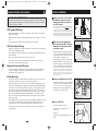
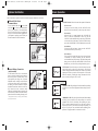
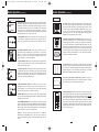
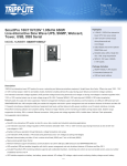
200308025 Smart1050-1500SLT Owner’s Manual.qxd
11/14/2003
11:40 AM
Page 1
Owner’s Manual
SmartPro SLT & SmartPro XL
®
®
Intelligent Tower (Accessory Slot-Equipped) UPS Systems
• Line-Interactive Operation • Sine-Wave Output • Extended Run (XL) Options
SmartPro SLT Models: SMART1050SLT & SMART1500SLT
SmartPro XL Model: SMART750XL
Important Safety Instructions
2
Quick Installation
3
Optional Installation
4
Basic Operation
5
Battery Replacement
9
Storage and Service
10
Specifications
11
Español
13
Français
25
1111 W. 35th Street Chicago, IL 60609 USA • Customer Support: (773) 869-1234 • www.tripplite.com
Copyright ©2003 Tripp Lite. All rights reserved. SmartPro® is a registered trademark of Tripp Lite.
200308025 Smart1050-1500SLT Owner’s Manual.qxd
11/14/2003
11:40 AM
Page 2
Important Safety Instructions
SAVE THESE INSTRUCTIONS
Quick Installation
1
This manual contains instructions and warnings that should be followed during the
installation, operation and storage of all Tripp Lite UPS Systems. Failure to heed these
warnings will void your warranty.
Note: if the Voltage Dip Switch setting does not match your
input voltage (if it is set above or below the input voltage),
the UPS system will naturally consider the input voltage as
a constant overvoltage or undervoltage condition. The UPS
system will respond accordingly by automatically adjusting
the input voltage to match the Voltage Dip Switch setting.
This will cause constant, unnecessary wear on the UPS system.
UPS Location Warnings
• Install your UPS indoors, away from excess moisture or heat, conductive contaminants,
dust or direct sunlight.
• For best performance, keep the indoor temperature between 32º F and 104º F (0º C and
40º C).
• Leave adequate space around all sides of the UPS for proper ventilation.
2
UPS Connection Warnings
• Connect your UPS directly to a properly grounded AC power outlet. Do not plug the UPS
into itself; this will damage the UPS.
• Do not use extension cords to connect the UPS to an AC outlet.
• If the UPS receives power from a motor-powered AC generator, the generator must
provide clean, filtered, computer-grade output.
Equipment Connection Warnings
Battery Warnings
3
• Unless your UPS system includes an external battery connector, do not attempt to add
external batteries.
SMART1050SLT shown
INPUT
2
SMART1050SLT shown
Plug your equipment into your UPS.
ACCESSORY
Your UPS is designed to support computer
equipment only. You will overload your UPS
if you connect devices with high power
demands such as household appliances or
laser printers to your UPS’s outlets.
• Because the batteries present a risk of electrical shock and burn from high short-circuit
current, observe proper precautions. Unplug and turn off the UPS before performing battery
replacement. Use tools with insulated handles, and replace the existing batteries with the
same number and type of new batteries (Sealed Lead-Acid). Do not open the batteries.
Do not short or bridge the battery terminals with any object. Tripp Lite offers a complete
line of UPS System Replacement Battery Cartridges (R.B.C.). Visit Tripp Lite on the
Web at www.tripplite.com/support/battery/index.cfm to locate the specific replacement
battery for your UPS.
• The UPS batteries are recyclable. Refer to local codes for disposal requirements, or in the
USA only call 1-800-SAV-LEAD or 1-800-8-BATTERY (1-800-8-228-8379) or visit
www.rbrc.com for recycling information. Do not dispose of the batteries in a fire.
1
Note: Once your UPS is plugged in, it will begin charging
its batteries. If this is the first time you have plugged in your
UPS, or if your UPS has been in storage for a prolonged
period, it will need to charge its batteries for at least 6
hours before it can support connected equipment in the
event of a power failure.
• Do not use Tripp Lite UPS Systems for life support appliances in which a malfunction
or failure of a Tripp Lite UPS System could cause failure or significantly alter the
performance of a life-support device.
• Your UPS does not require routine maintenance. Do not open your UPS for any reason
except battery replacement. There are no user-serviceable parts inside.
120V
110V
100V
127V
Plug one end of the detachable
line cord into your UPS’s AC Input
Receptacle and the other end into
an electrical outlet.
Plug the UPS directly into a properly grounded,
3-wire, 15-amp AC outlet that does not share
a circuit with a heavy electrical load (such as
an air conditioner, refrigerator, etc.).
After plugging your UPS in, check the Site
Wiring Fault LED on its rear panel. If it is lit,
the outlet is improperly wired; unplug the UPS
and have a qualified electrician check the outlet.
• Do not modify the UPS’s plug, and do not use an adapter that would eliminate the UPS’s
ground connection.
SI
W
FA
Using a small tool, set the Voltage
Dip Switch to match your input
voltage. (All models are preset to
the 120V setting.)
INPUT
3
4
Turn your UPS ON:
SMART1050SLT shown
SMART1050SLT shown
• Press the “ON/TEST” Switch
• Hold it for several seconds until you
hear a beep
ON/TEST
• Release it
OFF
Your UPS will begin providing power to its
outlets.
2
3
4
TRIMMING
200308025 Smart1050-1500SLT Owner’s Manual.qxd
11/14/2003
11:40 AM
Page 4
Optional Installation
Basic Operation
These connections are optional. Your UPS will function properly without these connections.
1
Front Panel Switches
USB and RS-232 Serial
Communications
“ON/TEST” Switch: This switch controls four separate UPS functions:
Use the included USB cable 1a and/or DB9
serial cable 1b to connect the communication
port on your computer to the communication
port of your UPS. Install on your computer the
Tripp Lite PowerAlert Software appropriate to
your computer’s operating system. Consult your
PowerAlert manual for more information.
UPS Power On
To turn power on at the outlets, press the “ON/TEST” switch,
hold it for several seconds until you hear a beep, then release it.
ON/TEST
SIGNAL
TVSS
1a
SMART1050SLT
shown
UPS Self-Test
When the UPS is in normal operation (the “VOLTAGE OK”
LED is on and the “ON BATTERY” LED is off), press the
“ON/TEST” switch and hold it until you hear a beep. This initiates
a 10-second self-test of the battery. The UPS will shift to battery
power (the “ON BATTERY” LED will illuminate) for ten seconds.
ACCESSORY
Alarm Silence
To silence the UPS “on-battery” alarm, press the “ON/TEST”
switch and hold it until you hear a beep.
SIGNAL
UPS Cold Start
To use your UPS as a stand-alone power source when AC power
is unavailable (i.e. during a blackout), press the “ON/TEST”
switch and hold it until you hear a beep. The UPS will then provide
battery power to its outlets. The “ON BATTERY” LED will be illuminated since your UPS will be operating from battery power.
TVSS
1b
SMART1050SLT
shown
ACCESSORY
ON/TEST
2
External Battery Connection
(select models)
110V
100V
127V
OFF
All UPS models come with a robust internal
battery system; select models feature connectors
that accept optional external battery packs
(sold separately from Tripp Lite*) to provide
additional runtime. Adding external batteries
will increase recharge time as well as runtime.
See battery pack owner’s manual for complete
installation instructions. Make sure cables are
fully inserted into their connectors. Small
sparks may result during battery connection; this
is normal. Do not connect or disconnect battery
packs when the UPS is running on battery power.
ACCESSORY
Front Panel Indicator Lights
2
SMART1050XL
shown
TRIMMING
NORMAL
“NORMAL” LED: This green light will be lit when the UPS is providing
AC utility power to connected equipment without needing to alter its
voltage.
BOOSTING
* See Specifications section for battery packs available for
your specific UPS model.
TRIMMING
NORMAL
4
“OFF” Switch: This switch turns power off at the outlets. Press this
switch, hold it until you hear a beep, then release it. The UPS will
continue charging its batteries and the fan will continue to cool internal
components even after you turn the UPS receptacles off. To turn the
UPS OFF completely, including the charger, disconnect the UPS’s
power cord after pressing the “OFF” switch.
“TRIMMING” LED: This yellow light be lit when the UPS is trimming
AC utility power to nominal levels and providing it to connected
equipment. The UPS will click faintly when trimming AC power.
This is a normal, automatic function of your UPS and no action is
required on your part. If your UPS has to trim power frequently, you
may be in a poor power area, and should consider obtaining power
protection for equipment that is not connected to a UPS.
5
200308025 Smart1050-1500SLT Owner’s Manual.qxd
Basic Operation
Front Panel Indicator Lights
NORMAL
11:40 AM
Page 6
Basic Operation
(continued)
OVERLOAD
AC Outlets: These 15-amp receptacles provide your connected equipment with voltage regulated AC output from the AC line during normal operation and from battery power during power failures. These
outlets also protect connected equipment against power surges on the
AC line. Your UPS is designed to support only computer equipment
with battery power. Do not connect equipment with high power
demands (like laser printers) to these outlets.
“ON BATTERY” LED: This yellow light will be lit when your UPS
is providing your equipment with battery power. The UPS will also
beep every two seconds, unless silenced by the “ON/TEST” Switch.
ON
BATTERY
Communications Ports (USB or RS-232): These ports connect your
UPS to any workstation or server. Use with Tripp Lite's PowerAlert
Software and included cables to enable your computer to automatically
save open files and shut down equipment during a blackout. Also use
PowerAlert Software to monitor a wide variety of AC line power and
UPS operating conditions. Consult your PowerAlert Software manual
or contact Tripp Lite Customer Support for more information. See “USB
and RS-232 Serial Communications” in the “Optional Installation”
section for installation instructions.
C
100%
“BATTERY METER” LEDs: These four green lights show the
approximate charge remaining in the UPS battery. If the battery
charge is very low, the 25% LED will flash and the UPS alarm will
beep every second to warn you that the remaining charge will be
depleted quickly by connected equipment.
80%
75%
60%
50%
40%
25%
20%
BATTERY
METER
LOAD
METER
“LOAD METER” LED: These four green lights show approximately how much of the UPS’s power capacity is used to support the equipment connected to the outlets.
Accessory Slot: Remove the small cover panel from this slot to install
optional accessories to remotely monitor and control your UPS. Refer
to your accessory’s manual for installation instructions. Contact Tripp Lite
Customer Support for more information, including a list of available
SNMP, network management and connectivity products.
“OVERLOAD” LED: This red light will be lit when the power draw
of equipment connected to the Battery, Surge and Noise Protected
outlets exceeds your UPS’s power capacity. The UPS alarm will beep
continuously. Immediately disconnect excess equipment from the
outlets until the light and alarm turn off.
OVERLOAD
80%
TVSS
ON
BATTERY
CHECK
BATTERY
100%
B
O
(continued)
Rear Panel
continued
“BOOSTING” LED: This yellow light will be lit when the UPS is
boosting AC utility power to nominal levels and providing it to connected
equipment. The UPS will click faintly when boosting AC power. This
is a normal, automatic function of your UPS and no action is required
on your part. If your UPS has to boost power frequently, you may be
in a poor power area, and should consider obtaining power protection
for equipment that is not connected to a UPS.
BOOSTING
C
11/14/2003
“CHECK BATTERY” LED: This red light will be lit if your UPS’s
microprocessor detects a battery fault or if the UPS battery is very
weakly charged. Let your UPS charge for 8 hours, then run another
self-test. If the light stays on, replace the batteries.
SHORT CIRCUIT: If a short circuit occurs, the UPS will stop providing
power to connected equipment and the alarm will sound. If this happens,
eliminate the short circuit.
OVERTEMPERATURE: If the temperature inside the UPS gets too
high, the NORMAL, BOOSTING, TRIMMING and ON BATTERY
LEDs will all light at once and the alarm will sound. If this happens,
check to make sure the UPS’s ventilation grills are unobstructed and
that it is located in a cool, well-ventilated area.
120V
110V
100V
127V
TVSS Cover Plate (Select Models Only): Remove this plate to
install optional modem/network surge protection modules, available
for purchase by special arrangement with Tripp Lite.
Voltage Dip Switch: Matches the UPS System’s output voltage to the
input voltage available at the wall outlet. See Quick Installation section
for setting instructions. Note: if the Voltage Dip Switch setting does not
match your input voltage (if it is set above or below the input voltage),
the UPS system will naturally consider the input voltage as a constant
overvoltage or undervoltage condition. The UPS system will respond
accordingly by automatically adjusting the input voltage to match the
Voltage Dip Switch setting. This will cause constant, unnecessary
wear on the UPS system.
FAULT: If the UPS detects an internal failure, its NORMAL,
BOOSTING and TRIMMING LEDs will light and its alarm will
sound. If this happens, disconnect the UPS and contact Tripp Lite for
service.
6
7
200308025 Smart1050-1500SLT Owner’s Manual.qxd
Basic Operation
Rear Panel
11/14/2003
11:40 AM
Page 8
Battery Replacement
(continued)
Under normal conditions, the original battery in your UPS will last several
years. Contact Tripp Lite for information about replacement batteries.
continued
Input Breaker: Protect your electrical circuit from overcurrent draw
from the UPS load. If this breaker trips, remove some of the load,
then reset it by pressing the breaker in.
1
1
Carefully pull the front panel down, out
and away from the UPS.
Be careful not to accidentally disconnect the ribbon cable connecting
the front panel to the rest of the UPS. Place the front panel on top
of the UPS, out of the way.
External Battery Connector (Select Models Only): Use to connect
Tripp Lite external battery packs for additional runtime. The specifications section of this manual lists the Tripp Lite external battery
packs that are compatible with your model. Refer to instructions
available with the battery pack for complete connection information
and safety warnings.
2
2
Unlock and lower the battery door.
3
Carefully pull the batteries from the UPS.
Replace batteries.
Carefully disconnect the old batteries from the UPS, then connect
the new batteries exactly as the old ones were connected, positive
(red) connectors together and negative (black) terminals together.
AC Input Receptacle: Connect one end of the detachable line cord
into this receptacle and the other end into your wall outlet.
Reassemble UPS.
3
Reverse Steps 1-3, above.
“SITE WIRING FAULT” LED: This red LED will be lit if the UPS
detects a problem with the wiring of the AC outlet you connect it to.
If this occurs, have the outlet inspected by a qualified electrician.
Note that while the UPS will detect many common wiring faults,
including a missing ground, reversed polarity and overloaded neutral
circuits, it cannot detect every conceivable wiring problem.
8
9
200308025 Smart1050-1500SLT Owner’s Manual.qxd
11/14/2003
11:40 AM
Page 10
Storage and Service
Specifications
Storage
Tripp Lite has a policy of continuous improvement. Specifications are subject to change without notice.
First turn your UPS OFF: press the “OFF” switch to turn power off at the outlets, then disconnect the power cord from the wall outlet. Next, disconnect all equipment to avoid battery drain.
If you plan on storing your UPS for an extended period of time, fully recharge the UPS batteries once every three months by plugging the UPS into a live AC outlet and letting the UPS
charge for 4-6 hours. If you leave your UPS batteries discharged for an extended period of
time, they may suffer permanent loss of capacity.
SmartPro SLT UPS Systems
Service
Before returning your UPS for service, follow these steps:
1. Review the installation and operation instructions in this manual to ensure that the service
problem does not originate from a misreading of the instructions. Also, check that the UPS
System’s circuit breaker(s) are not tripped. This is the most common cause of service
inquiries which can be easily remedied by following the resetting instructions in this manual.
2. If the problem continues, do not contact or return the UPS to the dealer. Instead, call Tripp Lite
at (773) 869-1233. A service technician will ask for the UPS’s model number, serial number
and purchase date and will attempt to correct the problem over the phone.
3. If the problem requires service, the technician will issue you a Returned Material
Authorization (RMA) number, which is required for service. If you require packaging, the
technician can arrange to send you proper packaging. Securely pack the UPS to avoid damage
during shipping. do not use Styrofoam beads for packaging. Any damages (direct, indirect,
special, incidental or consequential) to the UPS incurred during shipment to Tripp Lite or an
authorized Tripp Lite service center is not covered under warranty. UPS Systems shipped to
Tripp Lite or an authorized Tripp Lite service center must have transportation charges prepaid.
Mark the RMA number on the outside of the package. If the UPS System is within the 2-year
warranty period, enclose a copy of your sales receipt. Return the UPS for service using an
insured carrier to the address given to you by the Tripp Lite service technician.
Model:
Series #:
SMART1050SLT
AGSM1000DT
SMART1500SLT
AGSM1500DT
100, 110, 120 or 127 VAC
100, 110, 120 or 127 VAC
Input
Nominal Voltage:*
Frequency (± 3 Hz.):
60 Hz.
60 Hz.
Recommended Dedicated Electrical Circuit:
15 amp
15 amp
100, 110, 120 or 127 VAC
100, 110, 120 or 127 VAC
60 Hz.
60 Hz.
@ 127 VAC:
1050/670
1500/950
@ 120 VAC:
1050/670
1500/950
@ 110 VAC:
945/603
1350/855
@ 100 VAC:
840/536
1200/760
Output
Nominal Voltage:*
Frequency (± 3 Hz.):
Capacity (VA/Watts)
Waveform (Line and Battery Modes):
Maximum Harmonic Distortion (Linear Load/Non-Linear Load):
sine wave
sine wave
< 3% / < 6%
< 3% / < 6%
Battery
Battery Runtime (Half Load/Full Load) Minutes:
Battery Recharge Time (to 80% Capacity):
Transfer Time:
20/7
20/8
2-4 hours
2-4 hours
4-8 milliseconds
4-8 milliseconds
Battery System Voltage:
36 VDC
36 VDC
FCC:
Class B
Class B
UL, cUL, NOM
UL, cUL, NOM
Approvals:
SmartPro XL UPS System
Model:
Series #:
SMART750XL
AGSM751ST
Input
Nominal Voltage:*
100, 110, 120 or 127 VAC
Frequency (± 3 Hz.):
60 Hz.
Recommended Dedicated Electrical Circuit:
15 amp
Output
Nominal Voltage:*
Frequency (± 3 Hz.):
100, 110, 120 or 127 VAC
60 Hz.
Capacity (VA/Watts)
@ 127 VAC:
750/450
@ 120 VAC:
750/450
@ 110 VAC:
675/430
@ 100 VAC:
600/382
Waveform (Line and Battery Modes):
Maximum Harmonic Distortion (Linear Load/Non-Linear Load):
sine wave
< 3% / < 6%
Battery
Battery Runtime (Half Load/Full Load) Minutes:
Battery Recharge Time (to 80% Capacity):
Transfer Time:
Battery System Voltage:
FCC:
Approvals:
33/10+
2-4 hours
4-8 milliseconds
36 VDC
Class B
UL, cUL, NOM
* A set of user-selectable Voltage DIP Switches (see Quick Installation section) match the UPS system's output voltage to the input voltage available at the
wall outlet.
+ Battery runtime can be extended with the addition of optional Tripp Lite External Battery Packs (sold separately). SMART750XL models use BP36V27
battery packs. External batteries will increase both the battery runtime and the battery recharge time.
10
11
200308025 Smart1050-1500SLT Owner’s Manual.qxd
Specifications
11/14/2003
11:40 AM
Page 12
(continued)
FCC RADIO/TV INTERFERENCE NOTICE: Note: This equipment has been tested and found to comply with the limits for a Class
B digital device, pursuant to Part 15 of the FCC Rules. These limits are designed to provide reasonable protection against harmful
interference in a residential installation. This equipment generates, uses and can radiate radio frequency energy, and if not
installed and used in accordance with the instruction manual, may cause interference to radio communications. However, there
is no guarantee that interference will not occur in a particular installation. If this equipment does cause harmful interference to
radio or television reception, which can be determined by turning the equipment off and on, the user is encouraged to try to correct
the interference using one or more of the following measures: reorient or relocate the receiving antenna; increase the separation
between the equipment and the receiver; connect the equipment into an outlet on a circuit different from that which the receiver
is connected; consult the dealer or an experienced radio/television technician for help. The user must use shielded cables and
connectors with this product. Any changes or modifications to this product not expressly approved by the party responsible for
compliance could void the user's authority to operate the equipment. This device complies with part 15 of the FCC rules.
Operation is subject to the following 2 conditions: (1) This device may not cause harmful interference, and (2) This device must
accept any interference received, including interference that may cause undesired operation.
Note on Labeling
Manual del propietario
SmartPro SLT & SmartPro XL
®
®
Sistemas UPS inteligentes de torre (con ranuras auxiliares)
• Operación interactiva con la línea • Salida de onda sinusoidal
• Opción de tiempo de respaldo extendido (XL)
Modelos SmartPro SLT: SMART1050SLT y SMART1500SLT
Modelo SmartPro XL: SMART750XL
Two symbols are used on the label.
V~ : AC Voltage
V
: DC Voltage
Instrucciones de seguridad importantes
14
Instalación rápida
15
Instalación opcional
16
Operación básica
17
Reemplazo de batería
21
Almacenamiento y servicio
22
Especificaciones
23
English
1
Français
25
1111 W. 35th Street Chicago, IL 60609 USA • Soporte al cliente: (773) 869-1234 • www.tripplite.com
Copyright ©2003 Tripp Lite. Todos los derechos reservados. SmartPro® es una marca comercial registrada de Tripp Lite.
12
1111 W. 35th Street, Chicago, IL 60609 USA
773.869.1234 (USA) • 773.869.1212 (International)
www.tripplite.com
200308025 93-2178_ES