1
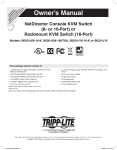
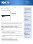
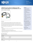
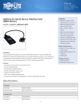
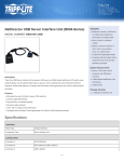
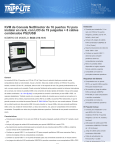
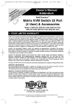
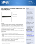
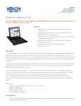
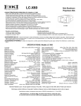
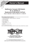
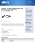
pr ch re od an gi R W uc ce ste eg ar t— to r o is ra w w nli tra nty w in n w. a e tio tri F to n pp R da : lit EE y f e. T o co ri r a m pp /w L ar ite ra nt y Quick Start Guide NetDirector Console KVM Switch (8- or 16-Port) or Rackmount KVM Switch (16-Port) Models: B020-U08-19-K, B020-U08-19KTAA, B020-U16-19-K or B022-U16 This Quick Start Guide will take you through basic installation, configuration and local operation. For more detailed information, refer to the Owner’s Manual on the CD-ROM. This Package Should Consist Of: • (1) B020-U08-19-K, B020-U08-19KTAA, B020-U16-19-K or B022-U16 KVM Switch • (8) P778-006 USB/PS2 Combo KVM Cable Kits* • (2) P778-006 USB/PS2 Combo KVM Cable Kits** • (1) USB/PS2 Combo Console Cable Kit • (1) RJ45 to DB9 Firmware Upgrade Cable • (1) C13 to 5-15P Power Cord* • (1) AC Power Adapter (Input: 100-240V, 50/60 Hz, 0.5A/Output: 5.3V, 2.4A)** • (1) CD with Owner’s Manual • (1) Quick Start Guide • (1) Grounding Wire • (1) Rackmount Hardware Kit • (1) Set of Rubber Feet** *B020-U08-19-K, B020-U08-19KTAA or B020-U16-19-K only **B022-U16 only Check to see that the unit arrived undamaged, with all of its contents. Contact your dealer if there is a problem. 1111 W. 35th Street, Chicago, IL 60609 USA www.tripplite.com/support NOTE: Follow these instructions and operating procedures to ensure correct performance and to prevent damage to this unit or to its connected devices. Copyright © 2010 Tripp Lite. All rights reserved. All trademarks are the property of their respective owners. 1 201005078 93-2901.indd 1 5/17/2010 4:35:48 PM 1. System Requirements 1.1 Computer • A VGA, SVGA or Multisync computer with an HD15 port Note: The max resolution for the B020-U08-19-K, B020-U08-19KTAA or B020-U16-19-K is 1280 x 1024, and 2048 x 1536 for the B022-U16. The resolutions of the connected computers must not exceed these limits. Either: 1.A mini DIN 6 (PS/2) keyboard and mouse port. 2.A USB Type-A port. 1.2 Console* • A VGA, SVGA, or Multisync monitor capable of the highest resolution that you will be using on any system in the installation • A PS/2 or USB style mouse • A PS/2 or USB style keyboard *Optional external console ports are included on the NetDirector Console KVM Switches. 1.3 Cables This KVM switch requires the following custom-wired premium cables: Function Tripp Lite Part To Connect a PS/2 or USB Computer to the KVM P778-Series PS/2 or USB Combo KVM Cable Kit Daisy-Chain Cables P772- Series Daisy-Chain Cables 1.4 Operating Systems OS Windows Linux RedHat Linux SuSE Linux Mandriva (Mandrake) UNIX AIX UNIX FreeBSD UNIX Sun Novell Netware Mac DOS Version 2000 and higher 7.1 and higher 9.0 and higher 9.0 and higher 4.3 and higher 4.2 and higher Solaris 8 and higher 5.0 and higher OS 9 and higher 6.22 2 201005078 93-2901.indd 2 5/17/2010 4:35:48 PM 2. Installation 2.1 Rackmounting Instructions for Console KVMs The NetDirector Console KVM Switch is designed for mounting in a 1U rack system. For convenience, a rack mounting kit is included with your KVM for quick installation. The various mounting options are explained in the sections that follow: Note: 1. It is recommended that the unit be installed by two people; one to hold it in place and the other to attach it to the rack. 2. The rackmounting kit that comes with the unit does not include screws or cage nuts. Contact your rack dealer for this hardware. 3. Allow at least 5.1 cm on each side for proper ventilation, and at least 12.7 cm at the rear of the unit for the power cord and cable kits. Standard Rackmounting 1 Slide out the rear mounting brackets from the console and mount both brackets (separate from the console) to the inside rear of a standard 1U rack system using usersupplied screws. 2 Take the console and gently slide it into the two rear-mounted brackets in the rack and secure the console in place by inserting user-supplied screws. 1 2 2-Post Rackmounting The NetDirector Console KVM Switch can also be mounted in a 2-post rack installation using the optional 2-Post Rackmount Kit (model: B019-000). The mounting hardware allows for the console to be opened with the drawer in any position. Heavy-duty 14-gauge steel provides stability and prevents the console frame from twisting. See the B019-000 instructional manual for detailed mounting instructions. 2.2 Rackmounting for B022-U16 Insert screws to connect to rack Fasten the rackmount brackets to the rack using user-supplied screws to install in a rack. 3 201005078 93-2901.indd 3 5/17/2010 4:35:48 PM 2. Installation 2.3 Single-Station Installation 1.Ensure that power to all the devices to be connected has been turned OFF. 5 2.Connect the included USB/PS2 Combo Console Cable Kit to the console connector on the back of the unit, and then connect a monitor, mouse and keyboard to the appropriate connectors on the cable kit. The distance between the external console and the KVM switch must not exceed 66 ft (20 m). Note: This step is mandatory for B022-U16 KVM Switches, but is optional for Console KVM Switches. 3 1 2 4 3.Use a P778-Series USB/PS2 Combo KVM Cable Kit to connect each CPU port to a computer/server. The distance between the KVM switch and each connected computer must not exceed 33 ft (10 m). 4.Plug the power cord or power adapter cable into the KVM’s power jack, then plug into a UPS, surge or other AC power source. Turn on the power switch for the console KVM. (Not required for the B022-U16.) 5.Turn ON the power to the computers. 2.4 Multiple Station (Daisy-Chained) Installation To control even more computers, up to 31 B022-016 or B022-U16 KVM Switches can be daisy-chained down from the first station. Note: As many as 512 computers can be controlled from the unit’s integrated console in a complete installation. To set up a daisy-chained installation: 1.Ensure that power to all the devices to be connected has been turned OFF. 2.Use a daisy-chain cable (described in the Cables section, page 2) to connect the Chain Out port of the parent unit to the Chain In port of the child unit. The distance between any two KVM switches in a daisy-chain must not exceed 49 ft (15 m). The distance between the first KVM switch and the last KVM switch in a daisychain must not exceed 328 ft (100 m), regardless of the number of KVM switches in the entire chain. 4 201005078 93-2901.indd 4 5/17/2010 4:35:48 PM 2. Installation 2.4 Multiple Station (Daisy-Chained) Installation 3.Use a KVM cable kit (described in the Cables section, page 2) to connect the keyboard, video and mouse ports of a computer to any available port on the KVM switch. The distance between the KVM switch and each connected computer must not exceed 33 ft (10 m). 4.Repeat the above steps for any additional KVM switches you wish to add to the chain. 5.Power up the installation according to the following procedure: a. Plug in the power adapter for the first station. Wait a few seconds to allow the unit to determine its Station ID. b. Plug in the power adapters for each subsequent station in the installation in turn (ie. second station, then third station, etc.). Each KVM switch has an LED display on its front panel to indicate its Station ID (the Station ID for the first station is 01, the ID for the second station is 02, the ID for the third station is 03, etc.). In each case, wait for the Station ID to be displayed on the Station ID LED before plugging in the next station. 2.5 Multiple Station (Cascaded) Installation The B022-U16 KVM Switch can be cascaded off of a B020-008-17-IP or B020-016-17-IP Console KVM Switch to expand the number of connected computers. Before you can start a cascaded installation, you must upgrade the B022-U16 firmware to be cascade compatible. (See the Firmware Upgrade section on page 18 of the owner’s manual for details.) For cascaded installation details, see the owner’s manual of the B020-008-17-IP or B020-016-17-IP Console KVM Switch. 5 201005078 93-2901.indd 5 5/17/2010 4:35:48 PM 3. Basic Operation 3.1 Opening the NetDirector Console KVM The console is located under the top cover. To access the console, slide the console module out and raise the cover. Note: As a safety precaution, to keep the console from accidentally sliding out, the console is locked into the in position. Before you can pull the console module out, you must release it by pushing the catches on the unit’s front panel toward the center of the switch. 3.2 Closing the NetDirector Console KVM To slide the console module back in, close the cover and do the following: 1.Pull the safety catches on the unit’s side rails toward you and push the module in until it stops. 2.Release the catches; pull the module slightly toward you; then push it all the way in. Note: The reason for the two-step procedure is to minimize the chances of pinching your fingers when sliding the module in. 4. OSD (On-Screen Display) Operation 4.1 OSD Overview The On-Screen Display (OSD) is a text-based interface that allows for control and administration of the KVM switch. When logging onto the KVM switch, the OSD Main Menu is the first screen you will see after entering your username and password. 4.2 Logging In For The First Time The KVM switch features a two-level security, with one Administrator and four User accounts. If you are an Administrator accessing the KVM switch for the first time, leave the username and password field blank and hit the [Enter] key twice to access the OSD Main Menu. Once logged into the KVM switch as Administrator, you will be able to access all OSD features and customize KVM settings. At this point, it is highly recommended that you change the Administrator username and password. 6 201005078 93-2901.indd 6 5/17/2010 4:35:48 PM 4. OSD (On-Screen Display) Operation continued 4.3 OSD Invocation Sequence Once logged into the KVM switch, you will need to use one of two sequences to open the OSD Main Menu; [Scroll Lock, Scroll Lock] or [Ctrl, Ctrl]. The default OSD invocation sequence is [Scroll Lock, Scroll Lock]. Note: When using the [Scroll Lock, Scroll Lock] OSD invocation sequence, you must hold down the [Fn] key, as the [Scroll Lock] key is part of the [Num Lock] key. F1:GOTO F3:SET F2:LIST F4:ADM ADMINISTRATOR LIST:ALL SN.PN QV X NAME 02 • 14 02 • 15 02 • 16 03 • 01 03 • 02 03 • 03 03 • 04 03 • 05 ABC COMP1 ABC COMP2 ABC COMP3 WEB SERVER 1 WEB SERVER 2 FAX SERVER 1 FAX SERVER 2 MAIL SERVER 1 X X X X X F5:SKP F6:BRC F7:SCAN F8:LOUT X zZ z When you invoke the OSD, a screen similar to the one above appears: Note: 1. The diagram depicts the Administrator’s Main Screen. The User Main Screen does not have the F4 and F6 functions, since they can’t be accessed by ordinary Users and are reserved for the Administrator. 2. OSD always starts in List view, with the highlight bar at the same position it was when it was last closed. 3. Only the ports that have been set accessible by the Administrator for the currently logged in User are visible. 4. If the port list is collapsed into stations, simply click on the plus sign next to the desired station number, or highlight the desired station number and hit the [Enter] key. 4.4 OSD Navigation • To close the menu and deactivate OSD, click the [X] at the upper right corner of the OSD Window; or press [Esc]. • To logout, press [F8], or click F8, on the OSD Menu Bar or click the zZz symbol at the upper right hand corner of the OSD Screen. • To move up or down one line at a time, click the Up and Down Triangle symbols () or use the Up and Down Arrow Keys. If there are more entries than appear on the screen, the screen will scroll. • To move up or down one screen at a time, click the Up and Down Arrow symbols (), or use the [Pg Up] and [Pg Dn] keys. If there are more entries than appear on the screen, the screen will scroll. • To activate a port, double-click it, or move the Highlight Bar to it then press [Enter]. • After executing any action, you automatically go back to the menu one level above. 7 201005078 93-2901.indd 7 5/17/2010 4:35:48 PM 5. Warranty 1-YEAR LIMITED WARRANTY TRIPP LITE warrants its products to be free from defects in materials and workmanship for a period of one (1) year from the date of initial purchase. TRIPP LITE's obligation under this warranty is limited to repairing or replacing (at its sole option) any such defective products. To obtain service under this warranty, you must obtain a Returned Material Authorization (RMA) number from TRIPP LITE or an authorized TRIPP LITE service center. Products must be returned to TRIPP LITE or an authorized TRIPP LITE service center with transportation charges prepaid and must be accompanied by a brief description of the problem encountered and proof of date and place of purchase. This warranty does not apply to equipment which has been damaged by accident, negligence or misapplication or has been altered or modified in any way. EXCEPT AS PROVIDED HEREIN, TRIPP LITE MAKES NO WARRANTIES, EXPRESS OR IMPLIED, INCLUDING WARRANTIES OF MERCHANTABILITY AND FITNESS FOR A PARTICULAR PURPOSE. Some states do not permit limitation or exclusion of implied warranties; therefore, the aforesaid limitation(s) or exclusion(s) may not apply to the purchaser. EXCEPT AS PROVIDED ABOVE, IN NO EVENT WILL TRIPP LITE BE LIABLE FOR DIRECT, INDIRECT, SPECIAL, INCIDENTAL OR CONSEQUENTIAL DAMAGES ARISING OUT OF THE USE OF THIS PRODUCT, EVEN IF ADVISED OF THE POSSIBILITY OF SUCH DAMAGE. Specifically, TRIPP LITE is not liable for any costs, such as lost profits or revenue, loss of equipment, loss of use of equipment, loss of software, loss of data, costs of substitutes, claims by third parties, or otherwise. 6. Warranty Registration Visit www.tripplite.com/warranty today to register the warranty for your new Tripp Lite product. You'll be automatically entered into a drawing for a chance to win a FREE Tripp Lite product!* * No purchase necessary. Void where prohibited. Some restrictions apply. See website for details. Regulatory Compliance Identification Numbers For the purpose of regulatory compliance certifications and identification, your Tripp Lite product has been assigned a unique series number. The series number can be found on the product nameplate label, along with all required approval markings and information. When requesting compliance information for this product, always refer to the series number. The series number should not be confused with the marking name or model number of the product. FCC Notice, Class A This device complies with part 15 of the FCC Rules. Operation is subject to the following two conditions: (1) This device may not cause harmful interference, and (2) this device must accept any interference received, including interference that may cause undesired operation. Note: This equipment has been tested and found to comply with the limits for a Class A digital device, pursuant to part 15 of the FCC Rules. These limits are designed to provide reasonable protection against harmful interference when the equipment is operated in a commercial environment. This equipment generates, uses, and can radiate radio frequency energy and, if not installed and used in accordance with the instruction manual, may cause harmful interference to radio communications. Operation of this equipment in a residential area is likely to cause harmful interference in which case the user will be required to correct the interference at his own expense. The user must use shielded cables and connectors with this equipment. Any changes or modifications to this equipment not expressly approved by Tripp Lite could void the user’s authority to operate this equipment. WEEE Compliance Information for Tripp Lite Customers and Recyclers (European Union) Under the Waste Electrical and Electronic Equipment (WEEE) Directive and implementing regulations, when customers buy new electrical and electronic equipment from Tripp Lite they are entitled to: •Send old equipment for recycling on a one-for-one, like-for-like basis (this varies depending on the country) •Send the new equipment back for recycling when this ultimately becomes waste Warning! Use of this equipment in life support applications where failure of this equipment can reasonably be expected to cause the failure of the life support equipment or to significantly affect its safety or effectiveness is not recommended. Do not use this equipment in the presence of a flammable anesthetic mixture with air, oxygen or nitrous oxide. Tripp Lite follows a policy of continuous improvement. Product specifications are subject to change without notice. 1111 W. 35th Street, Chicago, IL 60609 USA www.tripplite.com/support 8 201005078 93-2901.indd 8 201005078 • 932901-EN 5/17/2010 4:35:48 PM