1
Table of Content
1. INTRODUCTION .............................................................................................................................................. 1 1.1. 1.2. 1.3. 1.4. 2. INSTALLATION ................................................................................................................................................ 4 2.1. 2.2. 2.3. 3. BASIC ........................................................................................................................................................ 17 MODE: WDS.............................................................................................................................................. 19 ADVANCED ................................................................................................................................................ 20 SECURITY .................................................................................................................................................. 21 FILTER ....................................................................................................................................................... 25 WPS (WI-FI PROTECTED SETUP) ............................................................................................................... 26 CLIENT LIST............................................................................................................................................... 27 ISOLATION ................................................................................................................................................. 28 FIREWALL ....................................................................................................................................................... 29 7.1. 7.2. 7.3. 7.4. 7.5. 7.6. 7.7. 8. STATUS ...................................................................................................................................................... 13 DYNAMIC IP .............................................................................................................................................. 14 STATIC IP ................................................................................................................................................... 14 PPPOE ....................................................................................................................................................... 15 PPTP ......................................................................................................................................................... 16 WIRELESS 2.4GHZ & 5GHZ ........................................................................................................................ 17 6.1. 6.2. 6.3. 6.4. 6.5. 6.6. 6.7. 6.8. 7. VALID WAN CONNECTION ......................................................................................................................... 11 INVALID WAN CONNECTION...................................................................................................................... 11 WLAN SETUPS .......................................................................................................................................... 12 INTERNET ....................................................................................................................................................... 13 5.1. 5.2. 5.3. 5.4. 5.5. 6. STATUS ........................................................................................................................................................ 6 LAN ............................................................................................................................................................ 7 DHCP .......................................................................................................................................................... 8 SCHEDULE ................................................................................................................................................... 9 EVENT LOG .................................................................................................................................................. 9 MONITOR ................................................................................................................................................... 10 WIZARD ........................................................................................................................................................... 11 4.1. 4.2. 4.3. 5. SYSTEM REQUIREMENTS.............................................................................................................................. 4 LAN & WAN............................................................................................................................................... 4 LOGIN TO TEW-671BR ............................................................................................................................... 5 SYSTEM.............................................................................................................................................................. 6 3.1. 3.2. 3.3. 3.4. 3.5. 3.6. 4. SUMMARY .................................................................................................................................................... 1 WIRELESS PERFORMANCE CONSIDERATIONS ............................................................................................... 2 PACKAGE CONTENTS ................................................................................................................................... 3 PRODUCT LAYOUT ....................................................................................................................................... 3 ENABLE ..................................................................................................................................................... 29 ADVANCED ................................................................................................................................................ 29 DEMILITARIZED ZONE (DMZ) ................................................................................................................... 29 DENIAL OF SERVICE (DOS) ........................................................................................................................ 30 MAC FILTER.............................................................................................................................................. 31 IP FILTER ................................................................................................................................................... 32 URL FILTER ............................................................................................................................................... 33 ADVANCED ...................................................................................................................................................... 34 8.1. 8.2. 8.3. 8.4. 8.5. 8.6. 8.7. 8.8. 9. NETWORK ADDRESS TRANSLATION (NAT) ................................................................................................ 34 - PORT MAPPING ........................................................................................................................................ 34 PORT FORWARDING (VIRTUAL SERVER) ..................................................................................................... 35 PORT TRIGGERING (SPECIAL APPLICATIONS) ............................................................................................. 37 APPLICATION LAYER GATEWAY (ALG) ...................................................................................................... 38 UPNP ........................................................................................................................................................ 39 QUALITY OF SERVICE (QOS) ...................................................................................................................... 40 ROUTING.................................................................................................................................................... 42 TOOLS SETUP ................................................................................................................................................ 43 9.1. 9.2. 9.3. 9.4. 9.5. 9.6. 9.7. 9.8. PASSWORD ................................................................................................................................................. 43 TIME .......................................................................................................................................................... 44 DDNS........................................................................................................................................................ 44 POWER SAVINGS ........................................................................................................................................ 45 DIAGNOSIS ................................................................................................................................................. 45 FIRMWARE ................................................................................................................................................. 46 BACKUP ..................................................................................................................................................... 46 RESTART .................................................................................................................................................... 47 APPENDIX A – FCC INTERFERENCE STATEMENT ....................................................................................... 48 APPENDIX B – IC INTERFERENCE STATEMENT ........................................................................................... 48 ii
1. Introduction
1.1. Summary
TEW-671BR is a Dual Band Concurrent Wireless 11N Broadband Router with dual CPU
that offers user unprecedented network performance. WMM support boosts streaming
and multimedia intensive services. It supports 2.4GHz band under 802.11 b/g/n modes
while providing 5GHz band to guarantee an interference-free network access.
Multiple SSID provides advance users to manage multiple users of various needs. TX
power control enables flexible transmission tuning for different installation needs and
prevents malicious eaves-dropping. Isolation, filter, firewall and full coverage of security
standards promise a secure network environment.
Dual CPU operates work simultaneously therefore users can enjoy gaming, music or HD
video on 5GHz band while web-surfing or emailing on 2.4GHz. It also provides with
built-in 4-port full-duplex 10/100 Fast Switch that allows wired Ethernet for standard PC
and other network devices. TEW-671BR is definitely the optimal choice for both SOHO
and small business entities.
1
1.2. Wireless Performance Considerations
There are a number of factors that can impact the range of wireless devices.
1. Adjust your wireless devices so that the signal is traveling in a straight path, rather than at
an angle. The more material the signal has to pass through the more signal you will lose.
2. Keep the number of obstructions to a minimum. Each obstruction can reduce the range of a
wireless device. Position the wireless devices in a manner that will minimize the amount
of obstructions between them.
3. Building materials can have a large impact on your wireless signal. In an indoor
environment, try to position the wireless devices so that the signal passes through less
dense material such as dry wall. Dense materials like metal, solid wood, glass or even
furniture may block or degrade the signal.
4. Antenna orientation can also have a large impact on your wireless signal. Use the wireless
adapter’s site survey tool to determine the best antenna orientation for your wireless
devices.
5. Interference from devices that produce RF (radio frequency) noise can also impact your
signal. Position your wireless devices away from anything that generates RF noise, such
as microwaves, radios and baby monitors.
6. Any device operating on the 2.4GHz or 5GHz frequency will cause interference. Devices
such as 2.4GHz or 5GHz cordless phones or other wireless remotes operating on the
2.4GHz or 5GHz frequency can potentially drop the wireless signal. Although the phone
may not be in use, the base can still transmit wireless signal. Move the phone’s base
station as far away as possible from your wireless devices.
If you are still experiencing low or no signal consider repositioning the wireless devices or
installing additional access points. The use of higher gain antennas may also provide the
necessary coverage depending on the environment.
2
1.3. Package Contents
Open the package carefully, and make sure that none of the items listed below are missing.
Do not discard the packing materials, in case of return; the unit must be shipped back in its
original package.
‐ TEW-671BR Dual Band Wireless N Router
‐ Multi-Language Quick Installation Guide
‐ CD-ROM (User’s Guide)
‐ Cat.5 Ethernet cable (1m / 3.2ft)
‐ Power adapter (12V, 1A)
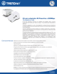
1.4. Product Layout
Physical Interface
z WAN: 1 * 10/100 Fast Ethernet RJ-45
z LAN: 4 * 10/100 Fast Ethernet RJ-45
z Reset Button (5 second for reboot, 5~10 seconds for reset
to factory default )
z Power Jack
z WPS push button (Wi-Fi Protected Setup)
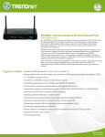
LEDs Status
z
z
z
z
z
z
Power/ Status
Internet (WAN)
LAN1~LAN4 (10/100Mbps)
WLAN 2.4GHz
WLAN 5GHz
WPS
3
2. Installation
2.1. System Requirements
To begin using the TEW-671BR, make sure you meet the following as minimum
requirements:
z
z
z
z
z
Operating System – Microsoft Windows 98SE/ME/XP/2000/VISTA
One Free Ethernet port on your PC or a Wireless client adapter
External xDSL (ADSL) or Cable modem with an Ethernet port (RJ-45).
PC/Laptop with Web-Browser application (Internet Explorer, Safari, Firefox, Opera etc.)
Cat.5 Ethernet cables (optional)
2.2. LAN & WAN
LAN connection:
Connect Ethernet cable between your PC/Laptop LAN port & one of the
4 available LAN ports on TEW-671BR.
WAN connection:
Connect Ethernet cable between WAN ports of your ADSL/CABLE
modem & internet port of TEW-671BR. Make sure your ADSL/CABLE
modem is working well. Contact your ISP if you have any questions.
4
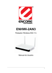
2.3. Login to TEW-671BR
TEW-671BR provides web-interface for configuration through web browser, such as
Internet Explorer (6.0 or above), Firefox or Safari.
1.
2.
3.
4.
Open your browser (e.g. Internet Explorer).
Type in http://192.168.10.1 in the address bar and click Enter.
You will be prompt with login window, the default username and password is admin
and admin. After you type in the login information, click OK.
You will see the System page of TEW-671BR as follows.
5
3. System
3.1. Status
This page allows you to monitor the current status of your router. You can use the status page
to quickly see if you have the latest firmware available. (For most updated firmware, please
visit http://www.trendnet.com/downloads)
System: You can see the unit up time, hardware information, serial number as well as
firmware version information.
WAN Settings: This section displays whether the WAN port is connected to a Cable/DSL
connection. It also displays the router’s WAN IP address, Subnet Mask, and ISP
Gateway as well as MAC address, the Primary DNS. Press Renew button to renew your
WAN IP address.
LAN Settings: This section displays the Broadband router LAN port’s current LAN & WLAN
information. It also shows whether the DHCP Server function is enabled / disabled.
WLAN Settings: This section displays the current WLAN configuration settings you’ve
configured in the Wizard / Basic Settings / Wireless Settings section. Wireless
configuration details such as SSID, Security settings, BSSID, Channel number, mode of
operation are briefly shown.
6
3.2. LAN
The LAN tab reveals LAN settings which can be altered at will. If you are an entry level
user, try accessing a website from your browser. If you can access website without a glitch,
just do not change any of these settings.
LAN IP
IP address: 192.168.10.1. It is the router’s default IP address. It can be changed based on
your own choice.
IP Subnet Mask: 255.255.255.0 Specify a Subnet Mask for your LAN segment.
802.1d Spanning Tree: This is disabled by default. If 802.1d Spanning Tree function is
enabled, this router will use the spanning tree protocol to prevent network loops.
DHCP Server
DHCP Server: This will enable or disable the Dynamic Pool setting..
Lease time: This is the lease time of each assigned IP address.
Start IP: This will be the beginning of the pool of IP addresses available for client devices.
End IP: This will be the end of the pool of IP addresses available for client devices.
Domain name: The Domain Name for the existing or customized network.
7
3.3. DHCP
View the current LAN clients which are assigned with an IP Address by the DHCP-server.
This page shows all DHCP clients (LAN PCs) currently connected to your network. The table
shows the assigned IP address, MAC address and expiration time for each DHCP leased
client. Use the Refresh button to update the available information. Hit Refresh to get the
updated table.
You can check “Enable Static DHCP IP“. It is possible to add more static DHCP IPs. They are
listed in the table “Current Static DHCP Table“. IP address can be deleted at will from the
table.
Note: Static DHCP IP means the PC with the particular MAC address will always receive the
same IP address from the DHCP server.
8
3.4. Schedule
This page allows user to set up schedule function for Firewall and Power Saving.
Add schedule, edit schedule options to allow configuration of firewall and power savings
services. Fill in the schedule and select type of service. Click Apply to implement those
settings. The schedule table lists the pre-schedule service-runs. You can select any of them
using the check box.
3.5. Event Log
View operation event log. This page shows the current system log of the Broadband
router. It displays any event occurred after system start up. At the bottom of the page, the
system log can be saved Save to a local file for further processing or the system log can be
cleared Clear or it can be refreshed Refresh to get the most updated information. When
the system is powered down, the system log will disappear if not saved to a local file.
9
3.6. Monitor
Show histogram for network connection on WAN, LAN & WLAN. Auto refresh keeps
information updated frequently.
10
4. Wizard
The wizard will take you step by step to setup your internet connection with the router.
Please make sure you have a valid internet connection from your ADSL/Cable modem to the
WAN port of TEW-671BR with active LED. After the router finished scaning the WAN port, you
will see either of the following 2 screens (section 4.1 & 4.2).
4.1. Valid WAN Connection
When you have a valid internet connection, you can select DHCP option if that’s your
connection type or Others when you have Static IP, PPPoE or PPTP type connections.
For detail internet connection settings, please refer to Section 5. And refer to section 4.3 for
Wizard’s wireless setups.
4.2. Invalid WAN Connection
The router was not able to find a valid connection, please check the cable connection and
make sure the WAN LED is on. After the verification, you can either use Rescan or choose
Manual Config to continue setting up the router manually.
Note: When pressing the Skip option, it will skip the Internet settings and go to Wireless
settings section.
For detail internet connection settings, please refer to Section 5. And refer to section 4.3 for
Wizard’s wireless setups.
11
4.3. WLAN Setups
We recommend you setting up the wireless encryptions immediately to protect your network.
To change security levels, please point to the bars, you can extend the security by clicking
next to the existing bar.
Security options from Lowest security with no encryption, WEP (Open) then Medium security
WEP (Shared Key), and High security WPA-PSK, and last Highest security WPA2-PSK.
12
5. Internet
5.1. Status
This page shows the current Internet connection type and status
Note: The Renew button works only when you have a Dynamic IP connection. When you
want to remotely manage the router, you can use the IP address shown here to access.
13
5.2. Dynamic IP
Use the MAC address when registering for Internet service, and do not change it unless
required by your Internet Services Provider (ISP). If your ISP used the MAC address of the
Ethernet card as an identifier, connect only the PC with the registered MAC address to the
broadband router and click the Clone MAC Address button. This will replace the current
MAC address with the already registered Ethernet card MAC address.
Host Name: This is optional.
MAC address: The default value is set to the WAN’s physical interface of the broadband
router. Most Dynamic IP connections do not require MAC Address therefore you can
leave this section blank if you think this does not apply to your account.
5.3. Static IP
If your ISP Provider has assigned a fixed IP address, you can enter the assigned IP address,
Subnet mask, Default Gateway IP address, and Primary DNS of your ISP provider.
When you have a Static IP account, you should have all the information above provided by
your ISP. If you don’t, please contact your ISP first.
14
5.4. PPPoE
For PPPoE connection, you should have a login name and password assigned from your
provider.
Login / Password: Enter the PPPoE username and password (Case sensitive)
Service Name: This is normally optional.
Maximum Transmission Unit (MTU): This is the maximum size of the packets.
Type: Enable the Auto-reconnect option to automatically re-establish the connection
when an application attempts to access the Internet again.
Idle Timeout: This is a maximum period of time for which the Internet connection is
maintained during inactivity. If the connection is inactive for longer than the
Maximum Idle Time, it will be dropped.
Note: you can leave the MTU, Authentication type, Type and idle Timeout settings as
default if you do not know what to choose.
15
5.5. PPTP
PPTP allows the secure connection over the Internet by simply dialing in a local point
provided by your ISP provider. The following screen allows client PCs to establish a normal
PPTP session and provides hassle-free configuration of the PPTP client on each client PC.
Host Name: This is optional.
MAC address: The default value is set to the WAN’s physical interface of the broadband
router.
Login / Password: Enter the PPTP username and password assigned by your ISP
provider.
Service Name: This is normally optional.
Maximum Transmission Unit (MTU): This is the maximum size of the packets.
Type: Enable the Auto-reconnect option to automatically re-establish the connection when
an application attempts to access the Internet again.
Idle Timeout: This is a maximum period of time for which the Internet connection is
maintained during inactivity. If the connection is inactive for longer than the
Maximum Idle Time, it will be dropped.
Note: you can leave the Host Name, MTU, Type and idle Timeout settings as default if you do
not know what to choose.
16
6. Wireless 2.4GHz & 5GHz
TEW-671BR is a dual band concurrent product, therefore two wireless radio configurations
are provided. Both radios share the same features except for open band and available
channels under “Basic” section.
6.1. Basic
17
Radio: You can turn on/off wireless radio. If wireless Radio is off, you cannot associate
with AP through wireless.
Mode: In this device, we support two operation modes which are AP router and WDS.
Band: You can select the wireless standards running on your network environment.
z 2.4G Band
2.4 GHz (802.11b/g): All 802.11b/g/n devices can connect to the router up to
54Mbps speed. You can select this option when your wireless clients are
all 802.11b/g devices.
2.4 GHz (802.11n): Only 802.11n compliant devices can connect to the
router at up to 300Mbps speed.
2.4 GHz (802.11b/g/n): All 802.11b/g/n devices can connect to the router at
their best speed.
z
5G Band
5 GHz (802.11a): If all of your clients are 802.11a, select this one.
5 GHz (802.11a/n): Either 802.11a or 802.11n wireless devices are in your
environment.
Enable ESSID: We support 4 multiple SSIDs in this device. Please select how many
SSIDs you would like to use in your network environment.
ESSID1~4: ESSID is the name of your wireless network. It might be a unique name to
identify this wireless device in the Wireless LAN. It is case sensitive and up to 32
printable characters. You might change the default ESSID for added security.
Auto Channel: Device will search all valid channels, then decide a most clean channel
and change to this channel if you enable this function. Depend on this function
enable or not, you will see different item below Auto Channel.
Channel: If Auto Channel is disabled, you should choose a static channel and AP will
use this channel to communicate with other clients.
Check Channel Time: If Auto Channel is enabled, you can choose a period from the
drop-down menu. Router will change to a clean channel periodically.
18
6.2. Mode: WDS
Wireless Distribution System, a system that enables the wireless interconnection of
access point, allows a wireless network to be expended using multiple access points
without a wired backbone to like them. Each WDS Router needs to set the same channel
and encryption type.
MAC address 1~4: Please enter the MAC address of the neighboring ROUTERs that
participates in WDS up to 4 devices.
Set Security: WDS Security depends on your router’s security settings. If you’ve setup
the encryption for your router, you do not have to configure again here. And if you
setup the encryptions here, your router’s security will be changed as well. Note: it
does not support mixed mode such as WPA-PSK/WPA2-PSK Mixed mode.
Note: TEW-671BR supports of up to 4 MAC addresses using WDS feature. All units
have to enter the other units’ MAC address to create a point to point or point to
multiple point bridge networks.
WDS security is separated from the AP’s security settings meaning you need to
configure the WDS encryption in this screen again once you change the mode to
WDS.
19
6.3. Advanced
This section allows you to set the advanced wireless options. The options included are
Authentication Type, Fragment Threshold, RTS Threshold, Beacon Interval, and Preamble
Type. You should not change these parameters unless you know what effect the changes
will have on the router.
Note: if you are not sure how to configure the settings in this section, we recommend you
to leave the settings as default. These settings are configured to provide the best
performance for common usage.
Fragment Threshold: This specifies the maximum size of a packet during the
fragmentation of data to be transmitted. If you set this value too low, it will result in bad
performance.
RTS Threshold: When the packet size is smaller than the RTS threshold, the wireless
router will not use the RTS/CTS mechanism to send this packet.
Beacon Interval: is the interval of time that this wireless router broadcasts a beacon. A
Beacon is used to synchronize the wireless network.
DTIM Period: Enter a value between 1 and 255 for the Delivery Traffic Indication
Message (DTIM). A DTIM is a countdown informing clients of the next window for
listening to broadcast and multicast messages
Data Rate: The “Data Rate” is the rate that this access point uses to transmit data packets.
The access point will use the highest possible selected transmission rate to transmit
the data packets.
N Data Rate: The “Data Rate” is the rate that this access point uses to transmit data
packets for N compliant wireless nodes. Highest to lowest data rate can be fixed.
20
Channel Bandwidth: This is the range of frequencies that will be used. 20/40MHz
provides the dual channel bandwidth support and gives you the connection speed of
up to 300Mbps. 20MHz provides single channel bandwidth and it provides you the
speed of up to 150Mbps.
Preamble Type: The “Long Preamble” can provide better wireless LAN compatibility while
the “Short Preamble” can provide better wireless LAN performance.
CTS Protection: It is recommended to enable the protection mechanism. This mechanism
can decrease the rate of data collision between 802.11b and 802.11g wireless
stations. When the protection mode is enabled, the throughput of the Router will be a
little lower due to a lot of frame-network that is transmitted.
TX Power: This can be set to a bare minimum or maximum power.
6.4. Security
This Access Point provides complete wireless LAN security functions, included are WEP,
IEEE 802.1x, WPA with pre-shared key and WPA with RADIUS. With these security
functions, you can prevent your wireless LAN from illegal access. Please make sure your
wireless stations use the same security function, and are setup with the same security key.
ESSID Selection: This broadband router support multiple ESSID, you could select
and set up the wanted ESSID.
Broadcast ESSID: If you enabled “Broadcast ESSID”, every wireless station located
within the coverage of this access point can discover this access point easily. If
you are building a public wireless network, enabling this feature is recommended.
WMM: Wi-Fi Multi-Media if enabled supports QoS for experiencing better audio, video
and voice in applications.
Encryption: When you choose to disable encryption, it is very insecure to operate
TEW-671BR.
21
Enable 802.1x Authentication
IEEE 802.1x is an authentication protocol. Every user must use a valid account to login to
this Access Point before accessing the wireless LAN. The authentication is processed by a
RADIUS server. This mode only authenticates users by IEEE 802.1x, but it does not
encrypt the data during communication.
WEP Encryption
When you select 64-bit or 128-bit WEP key, you have to enter WEP keys to encrypt data.
You can generate the key by yourself and enter it. You can enter four WEP keys and select
one of them as a default key. Then the router can receive any packets encrypted by one of
the four keys. WEP provides basic level or security, if you would like to use higher security
encryption, please consider WPA2 encryption.
22
Authentication Type: There are two authentication types: "Open System" and "Shared
Key". When you select "Open System", wireless stations can associate with this
wireless router without WEP encryption. When you select "Shared Key", you should
also setup a WEP key in the "Encryption" page. After this has been done, make
sure the wireless clients that you want to connect to the device are also setup with the
same encryption key.
Key Length: You can select the WEP key length for encryption, 64-bit or 128-bit. The
larger the key will be the higher level of security is used, but the throughput will be
lower.
Key Type: You may select ASCII Characters (alphanumeric format) or Hexadecimal Digits
(in the "A-F", "a-f" and "0-9" range) to be the WEP Key.
Key1 - Key4: The WEP keys are used to encrypt data transmitted in the wireless network.
Use the following rules to setup a WEP key on the device. 64-bit WEP: input 10-digits
Hex values (in the "A-F", "a-f" and "0-9" range) or 5-digit ASCII character as the
encryption keys.
128-bit WEP: input 26-digit Hex values (in the "A-F", "a-f" and "0-9" range) or 13-digit
ASCII characters as the encryption keys.
Click Apply at the bottom of the screen to save the above configurations. You can now
configure other sections by choosing Continue, or choose Apply to apply the settings and
reboot the device.
WPA Pre-Shared Key Encryption
Wi-Fi Protected Access (WPA) is an advanced security standard. You can use a
pre-shared key to authenticate wireless stations and encrypt data during communication. It
supports TKIP (WPA-PSK) or AES (WPA2-PSK) encryptions; this is the best security
available.
23
WPA-Radius Encryption
Wi-Fi Protected Access (WPA) is an advanced security standard. You can use an external
RADIUS server to authenticate wireless stations and provide the session key to encrypt
data during communication.
It supports TKIP (WPA) or AES (WPA2) encryptions. Press Apply button when you are
done.
24
6.5. Filter
This wireless router supports MAC Address Control, which prevents unauthorized clients
from accessing your wireless network.
Enable wireless access control: Enable the wireless access control function
Adding an address into the list
Enter the "MAC Address" and "Comment" of the wireless station to be added and
then click Add. The wireless station will now be added into the "Current Access
Control List" below. If you are having any difficulties filling in the fields, just click
"Clear" and both "MAC Address" and "Comment" fields will be cleared.
Remove an address from the list
If you want to remove a MAC address from the "Current Access Control List ", select
the MAC address that you want to remove in the list and then click "Delete Selected".
If you want to remove all the MAC addresses from the list, just click the Delete All
button. Click Reset will clear your current selections.
Click Apply at the bottom of the screen to save the above configurations.
25
6.6. WPS (Wi-Fi Protected Setup)
WPS is the simplest way to establish a connection between the wireless clients and the
wireless router. You don’t have to select the encryption mode and fill in a long encryption
passphrase every time when you try to setup a wireless connection. You only need to
press a button on both wireless client and wireless router, and the WPS will do the rest for
you.
The wireless router supports two types of WPS: WPS via Push Button and WPS via PIN
code. If you want to use the Push Button, you have to push a specific button on the wireless
client or in the utility of the wireless client to start the WPS mode, and switch the wireless
router to WPS mode. You can simply push the WPS button of the wireless router, or click
the ‘Start to Process’ button in the web configuration interface. If you want to use the PIN
code, you have to know the PIN code of the wireless client and switch it to WPS mode, then
fill-in the PIN code of the wireless client through the web configuration interface of the
wireless router.
WPS: Check the box to enable WPS function and uncheck it to disable the WPS function.
WPS Current Status: If the wireless security (encryption) function of this wireless router is
properly set, you’ll see a ‘Configured’ message here. Otherwise, you’ll see
‘UnConfigured’. The router will automatically enable encryption when you setup the
WPS from default settings. Any WPS connection made after the router has been
modified, the encryption type will stay as is.
Self Pin Code: This is the WPS PIN code of the wireless router. You may need this
information when connecting to other WPS-enabled wireless devices.
SSID: This is the network broadcast name (SSID) of the router.
Authentication Mode: It shows the active authentication mode for the wireless
connection.
Passphrase Key: It shows the passphrase key that is randomly generated by the wireless
router during the WPS process. You may need this information when using a device
which doesn’t support WPS.
26
Interface: If device is set to repeater mode, you can choose “Client” interface to connect
with other AP by using WPS, otherwise you may choose “AP” interface to do WPS
with other clients.
WPS via Push Button: Press the button to start the WPS process. The router will wait for
the WPS request from the wireless devices within 2 minutes.
WPS via PIN: You can fill-in the PIN code of the wireless device such as your wireless
adapter and press the button to start the WPS process. The router will wait for the
WPS request from the wireless device within 2 minutes.
Note: when connecting to the router via WPS, your wireless devices needs to support
WPS. Otherwise you need to manually connect your wireless device to the router
with all the proper settings such as SSID, encryptions and etc.
6.7. Client List
This WLAN Client Table shows the Wireless client associate to this Wireless Router.
Note: if you want to make your wireless network more secure, you can either setup
encryptions as well as using MAC address filter to block any unwanted access.
27
6.8. Isolation
Policy provides a list of control policies. These settings define whether wireless or wired
clients are able to “see” each in the LAN.
z
z
z
z
z
If you are offering Internet access to your clients, please enable WAN connection.
If you allow communication between Wireless clients please enable the second item.
If you allow communication between Wireless client and Wired client please enable
the last item.
Disable WAN connection if you do not provide Internet access.
Disable the items if you would like to enhance privacy between clients.
Note: By default all communications between internet/wired/wireless connections are enabled.
If you would like to block certain access, select Disable from the desire field and click Apply
to save the settings. You can make these configurations based on each SSID.
28
7. Firewall
7.1. Enable
The Broadband router provides extensive firewall protection by restricting connection
parameters, thus limiting the risk of hacker attacks, and defending against a wide array of
common Internet attacks. However, for applications that require unrestricted access to the
Internet, you can configure a specific client/server as a Demilitarized Zone (DMZ).
7.2. Advanced
If you are using some VPN access for your work or other purpose, you can enable the
options here to pass the VPN packets correctly. These options are enabled by default, the
router is not a VPN server or client, it only pass through the packets.
Note: For VPN connections, it might require to open some ports when you run your PC
behind a router. For port information, please refer to each VPN software’s help site.
7.3. Demilitarized Zone (DMZ)
If you have a client PC that cannot run an Internet application (e.g. Games) properly from
behind the NAT firewall, then you can open up the firewall restrictions to unrestricted
two-way Internet access by defining a DMZ Host. The DMZ function allows you to re-direct
all packets going to your WAN port IP address to a particular IP address in your LAN. The
difference between the virtual server and the DMZ function is that the virtual server
re-directs a particular service/Internet application (e.g. FTP, websites) to a particular LAN
client/server, whereas DMZ re-directs all packets (regardless of services) going to your
WAN IP address to a particular LAN client/server.
29
Enable DMZ: Enable/disable DMZ
LAN IP Address: Fill-in the IP address of a particular host in your LAN Network that will
receive all the packets originally going to the WAN port/Public IP address above.
Click Apply at the bottom of the screen to save the above configurations.
Note: When enabling DMZ, you are allowing your PC to be accessed by public without
any protection. It is not recommended.
7.4. Denial of Service (DoS)
The Broadband router's firewall can block common hacker attacks, including Denial of
Service, Ping of Death, Port Scan and Sync Flood. If Internet attacks occur the router can
log the events.
Ping of Death: Protections from Ping of Death attack.
Discard Ping From WAN: The router’s WAN port will not respond to any Ping requests
Port Scan: Protects the router from Port Scans.
Sync Flood: Protects the router from Sync Flood attack.
30
7.5. MAC Filter
If you want to restrict users from accessing certain Internet applications / services (e.g.
Internet websites, email, FTP etc.), and then this is the place to set that configuration.
Access Control allows users to define the traffic type permitted in your LAN. You can
control which PC client can have access to these services.
Enable MAC Filtering: Check to enable or disable MAC Filtering.
Deny: If you select “Deny” then all clients will be allowed to access Internet accept for the
clients in the list below.
Allow: If you select “Allow” then all clients will be denied to access Internet accept for the
PCs in the list below.
Add PC MAC Address
Fill in “LAN MAC Address” and Description of the PC that is allowed to access the
Internet, and then click Add. If you find any typo before adding it and want to retype
again, just click Reset and the fields will be cleared.
Remove PC MAC Address
If you want to remove some PC from the "MAC Filtering Table", select the PC you
want to remove in the table and then click Delete Selected. If you want to remove all
PCs from the table, just click the Delete All button. If you want to clear the selection
and re-select again, just click Reset.
Click Apply at the bottom of the screen to save the above configurations.
31
7.6. IP Filter
Enable IP Filtering: Check to enable or disable IP Filtering.
Deny: If you select “Deny” then all clients will be allowed to access Internet accept for the
clients in the list below.
Allow: If you select “Allow” then all clients will be denied to access Internet accept for the
PCs in the list below.
Add PC IP Address
You can click <Add> PC to add an access control rule for users by an IP address or IP
address range.
Remove PC IP Address
If you want to remove some PC IP from the IP Filtering Table, select the PC you
want to remove in the table and then click Delete Selected. If you want to remove all
PCs from the table, just click the Delete All button.
Click Apply at the bottom of the screen to save the above configurations.
32
7.7. URL Filter
You can block access to some Web sites from particular PCs by entering a full URL
address or just keywords of the Web site.
Enable URL Blocking: Enable or disable URL Blocking
Add URL Keyword
Fill in “URL/Keyword” and then click Add. You can enter the full URL address or the
keyword of the web site you want to block. If you happen to make a mistake and
want to retype again, just click "Reset" and the field will be cleared.
(eg. If you want to block www.badcontents.com, you can either type in
www.badcontents.com or badconents in the field. Both ways will block the site)
Remove URL Keyword
If you want to remove some URL keywords from the "Current URL Blocking
Table", select the URL keyword you want to remove in the table and then click
Delete Selected.
If you want remove all URL keywords from the table, click Delete All button. If you
want to clear the selection and re-select again, just click Reset.
Click Apply at the bottom of the screen to save the above configurations
33
8. Advanced
8.1. Network Address Translation (NAT)
Network Address Translation (NAT) allows multiple users at your local site to access the
Internet through a single Public IP Address or multiple Public IP Addresses. NAT provides
Firewall protection from hacker attacks and has the flexibility to allow you to map Private IP
Addresses to Public IP Addresses for key services such as Websites and FTP. Select
Disable to disable the NAT function.
8.2. - Port Mapping
Port Mapping allows you to re-direct a particular range of service port numbers (from the
Internet / WAN Port) to a particular LAN IP address. It helps you to host servers behind the
router NAT firewall.
Enable Port Mapping: Enable or disable port mapping function.
34
Description: description of this setting.
Local IP: This is the local IP of the server behind the NAT firewall.
Type: This is the protocol type to be forwarded. You can choose to forward “TCP” or “UDP”
packets only, or select “BOTH” to forward both “TCP” and “UDP” packets.
Port Range: The range of ports to be forward to the private IP.
Add Port Mapping
Fill in the "Local IP", “Type”, “Port Range” and "Description" of the setting to be
added and then click "Add". Then this Port Mapping setting will be added into the
"Current Port Mapping Table" below. If you find any typo before adding it and want
to retype again, just click Clear and the fields will be cleared.
Remove Port Mapping
If you want to remove a Port Mapping setting from the "Current Port Mapping
Table", select the Port Mapping setting that you want to remove in the table and then
click Delete Selected. If you want to remove all Port Mapping settings from the table,
click Delete All button. Click Reset will clear your current selections.
Click Apply at the bottom of the screen to save the above configurations.
8.3. Port Forwarding (Virtual Server)
Use the Port Forwarding (Virtual Server) function when you want different servers/clients in
your LAN to handle different service/Internet application type (e.g. Email, FTP, Web server
etc.) from the Internet. Computers use numbers called port numbers to recognize a
particular service/Internet application type. The Virtual Server allows you to re-direct a
particular service port number (from the Internet/WAN Port) to a particular LAN private IP
address and its service port number.
35
Enable Port Forwarding: Enable or disable Port Forwarding.
Description: The description of this setting.
Local IP / Local Port: This is the LAN Client/Host IP address and Port number that the
Public Port number packet will be sent to.
Type: Select the port number protocol type (TCP, UDP or both). If you are unsure, then
leave it to the default “both” setting. Public Port enters the service (service/Internet
application) port number from the Internet that will be re-directed to the above Private
IP address host in your LAN Network.
Public Port: Port number will be changed to Local Port when the packet enters your LAN
Network.
Add Port Forwarding
Fill in the "Description" , "Local IP", "Local Port", "Type" and “Public Port” of the
setting to be added and then click Add button. Then this Virtual Server setting will be
added into the "Current Port Forwarding Table" below. If you find any typo before
adding it and want to retype again, just click Clear and the fields will be cleared.
Remove Port Forwarding
If you want to remove Port Forwarding settings from the "Current Port Forwarding
Table", select the Port Forwarding settings you want to remove in the table and then
click "Delete Selected". If you want to remove all Port Forwarding settings from the
table, just click the Delete All button. Click Reset will clear your current selections.
Click Apply at the bottom of the screen to save the above configurations.
36
8.4. Port Triggering (Special Applications)
Some applications require multiple connections, such as Internet games, video
Conferencing, Internet telephony and others. In this section you can configure the router to
support multiple connections for these types of applications.
Enable Trigger Port: Enable or disable the Port Trigger function.
Trigger Port: This is the outgoing (Outbound) range of port numbers for this particular
application.
Trigger Type: Select whether the outbound port protocol is “TCP”, “UDP” or “BOTH”.
Public Port: Enter the In-coming (Inbound) port or port range for this type of application
(e.g. 2300-2400, 47624)
Public Type: Select the Inbound port protocol type: “TCP”, “UDP” or “BOTH”
Popular Applications: This section lists the more popular applications that require
multiple connections. Select an application from the Popular Applications selection.
Once you have selected an application, select a location (1-10) in the Copy to
selection box and then click the Copy to button. This will automatically list the Public
Ports required for this popular application in the location (1-10) you specified.
Add Port Triggering
Fill in the "Trigger Port", "Trigger Type”, “Public Port”, "Public Type", "Public
Port" and "Description" of the setting to be added and then Click Add. The Port
Triggering setting will be added into the "Current Trigger-Port Table" below. If you
happen to make a mistake, just click Clear and the fields will be cleared.
37
Remove Port Triggering
If you want to remove Special Application settings from the "Current Trigger-Port
Table", select the Port Triggering settings you want to remove in the table and then
click Delete Selected. If you want remove all Port Triggering settings from the table,
just click the Delete All button. Click Reset will clear your current selections.
8.5. Application Layer Gateway (ALG)
You can select applications that need ALG support. The router will let the selected application
to correctly pass through the NAT gateway.
38
8.6. UPNP
With UPnP, all PCs in you Intranet will discover this router automatically. So, you don’t
have to configure your PC and it can easily access the Internet through this router.
Enable/Disable UPnP: You can enable or Disable the UPnP feature here. After you
enable the UPnP feature, all client systems that support UPnP, like Windows XP, can
discover this router automatically and access the Internet through this router without
having to configure anything. The NAT Traversal function provided by UPnP can let
applications that support UPnP connect to the internet without having to configure the
virtual server sections.
39
8.7. Quality of Service (QoS)
QoS can let you classify Internet application traffic by source/destination IP address and
port number. You can assign priority for each type of application and reserve bandwidth for
it. The packets of applications with higher priority will always go first. Lower priority
applications will get bandwidth after higher priority applications get enough bandwidth. This
can let you have a better experience in using critical real time services like Internet phone,
video conference …etc. All the applications not specified by you are classified as rule
“Others”.
Priority Queue Type:
This can put the packets of specific protocols in High/Low Queue. The packets in High
Queue will process first.
Unlimited Priority Queue: The LAN IP address will not be bounded in the QoS limitation.
High/Low Priority Queue: This can put the packets in the protocol and port range to
High/Low QoS Queue.
40
Bandwidth Allocation:
This can reserve / limit the throughput of specific protocols and port range. You can set the
upper bound and Lower bound.
Type: Specify the direction of packets. Upload or download.
IP range: Specify the IP address range. You could also fill one IP address
Protocol: Specify the packet type. The default ALL will put all packets in the QoS priority
Queue.
Port range: Specify the Port range. You could also fill one Port.
Policy: Specify the policy the QoS, Min option will reserve the selected data rate in QoS
queue. Max option will limit the selected data rate in QoS queue.
Rate: The data rate of QoS queue.
Note: If you select Min for Policy and 4M for Rate, the router will reserve at least 4Mbps
data rate dedicated for the targeted protocol and IP range.
Disabled:
This could turn off QoS feature.
41
8.8. Routing
You can set enable Static Routing to let the router forward packets by your routing policy.
Static Route is used when network administrators need to route the packets to a different
subnet with certain path. This type of setups is not for home users, you can skip this section
if this does not apply to you.
Destination LAN IP: Specify the destination LAN IP address of static routing rule.
Subnet Mask: Specify the Subnet Mask of static routing rule.
Default Gateway: Specify the default gateway of static routing rule.
Hops: Specify the Max Hops number of static routing rule.
Interface: Specify the Interface of static routing rule.
42
9. Tools Setup
9.1. Password
You can change the password required to log into the broadband router's system
web-based management. By default, the password is: admin. Passwords can contain 0 to
12 alphanumeric characters, and are case sensitive.
Current Password: Fill in the current password to allow changing to a new password.
New Password: Enter your new password and type it again in Repeat New Password for
verification purposes
Remote management
This allows you to designate a host in the Internet the ability to configure the
Broadband router from a remote site. Enter the designated host IP Address in the
Host IP Address field.
Host Address: This is the IP address of the host in the Internet that will have
management/configuration access to the Broadband router from a remote site. If the
Host Address is left 0.0.0.0 this means anyone can access the router’s web-based
configuration from a remote location, providing they know the password.
Port: The port number of the remote management web interface.
Enabled: Check to enable the remote management function.
Click Apply at the bottom of the screen to save the above configurations.
43
9.2. Time
The Time Zone allows your router to reference or base its time on the settings configured
here, which will affect functions such as Log entries and Firewall settings.
Time Zone: Select the time zone of the country you are currently in. The router will set its
time based on your selection.
NTP Time Server: The router can set up external NTP Time Server.
Daylight Savings: The router can also take Daylight Savings into account. If you wish to
use this function, you must select the Daylight Savings Time period and check/tick
the enable box to enable your daylight saving configuration.
Click Apply at the bottom of the screen to save the above configurations.
9.3. DDNS
DDNS allows you to map the static domain name to a dynamic IP address. You must get
an account, password and your static domain name from the DDNS service providers. This
router supports DynDNS, TZO and other common DDNS service providers.
44
Enable/Disable DDNS: Enable or disable the DDNS function of this router
Server Address: Select a DDNS service provider
Host Name: Fill in your static domain name that uses DDNS.
Username: The account that your DDNS service provider assigned to you.
Password: The password you set for the DDNS service account above
Click Apply at the bottom of the screen to save the above configurations.
9.4. Power Savings
Saving power in WLAN mode can be enabled/disabled in this page.
9.5. Diagnosis
This section could let you diagnosis your current network status by using PING
command.
45
9.6. Firmware
This page allows you to upgrade the router’s firmware. To upgrade the firmware of your
Broadband router, you need to download the firmware file to your local hard disk, and enter
that file name and path in the appropriate field on this page. You can also use the Browse
button to find the firmware file on your PC.
Once you’ve selected the new firmware file, click Apply at the bottom of the screen to start
the upgrade process
9.7. Backup
This page allows you to save the current router configurations. When you save the
configurations, you also can re-load the saved configurations into the router through the
Restore Settings. If extreme problems occur you can use the Restore to Factory Defaults to
set all configurations to its original default settings.
Backup Settings: This can save the Broadband router current configuration to a file
named "config.bin" on your PC. You can also use the Upload button to restore the
saved configuration to the Broadband router. Alternatively, you can use the "Restore
to Factory Defaults" tool to force the Broadband router to perform a power reset and
restore the original factory settings.
46
9.8. Restart
You can reset the router when system stops responding correctly or stop functions.
47
Appendix A – FCC Interference Statement
Federal Communication Commission Interference Statement
This equipment has been tested and found to comply with the limits for a Class B digital device, pursuant to
Part 15 of the FCC Rules. These limits are designed to provide reasonable protection against harmful
interference in a residential installation. This equipment generates, uses and can radiate radio frequency
energy and, if not installed and used in accordance with the instructions, may cause harmful interference to
radio communications. However, there is no guarantee that interference will not occur in a particular
installation. If this equipment does cause harmful interference to radio or television reception, which can be
determined by turning the equipment off and on, the user is encouraged to try to correct the interference by
one of the following measures:
z
z
z
z
Reorient or relocate the receiving antenna.
Increase the separation between the equipment and receiver.
Connect the equipment into an outlet on a circuit different from that to which the receiver is connected.
Consult the dealer or an experienced radio/TV technician for help.
This device complies with Part 15 of the FCC Rules. Operation is subject to the following two conditions: (1)
This device may not cause harmful interference, and (2) this device must accept any interference received,
including interference that may cause undesired operation.
FCC Caution: Any changes or modifications not expressly approved by the party responsible for compliance
could void the user's authority to operate this equipment.
IMPORTANT NOTE:
FCC Radiation Exposure Statement:
This equipment complies with FCC radiation exposure limits set forth for an uncontrolled environment. This
equipment should be installed and operated with minimum distance 20cm between the radiator & your body.
We declare that the product is limited in CH1~CH11 by specified firmware controlled in the USA.
This transmitter must not be co-located or operating in conjunction with any other antenna or transmitter.
Appendix B – IC Interference Statement
Industry Canada statement:
This device complies with RSS-210 of the Industry Canada Rules. Operation is subject to the following two
conditions:
(1) This device may not cause harmful interference, and (2) this device must accept any interference received,
including interference that may cause undesired operation.
IMPORTANT NOTE:
Radiation Exposure Statement:
This equipment complies with IC radiation exposure limits set forth for an uncontrolled environment. This
equipment should be installed and operated with minimum distance 20cm between the radiator & your body.
This device has been designed to operate with an antenna having a maximum gain of 2 dBi. Antenna having a
higher gain is strictly prohibited per regulations of Industry Canada. The required antenna impedance is 50 ohms.
48
Limited Warranty TRENDnet warrants its products against defects in material and workmanship, under normal use and service, for the following lengths of time from the date of purchase. TEW‐671BR – 3 Years Warranty AC/DC Power Adapter, Cooling Fan, and Power Supply carry 1 year warranty. If a product does not operate as warranted during the applicable warranty period, TRENDnet shall reserve the right, at its expense, to repair or replace the defective product or part and deliver an equivalent product or part to the customer. The repair/replacement unit’s warranty continues from the original date of purchase. All products that are replaced become the property of TRENDnet. Replacement products may be new or reconditioned. TRENDnet does not issue refunds or credit. Please contact the point‐of‐purchase for their return policies. TRENDnet shall not be responsible for any software, firmware, information, or memory data of customer contained in, stored on, or integrated with any products returned to TRENDnet pursuant to any warranty. There are no user serviceable parts inside the product. Do not remove or attempt to service the product by any unauthorized service center. This warranty is voided if (i) the product has been modified or repaired by any unauthorized service center, (ii) the product was subject to accident, abuse, or improper use (iii) the product was subject to conditions more severe than those specified in the manual. Warranty service may be obtained by contacting TRENDnet within the applicable warranty period and providing a copy of the dated proof of the purchase. Upon proper submission of required documentation a Return Material Authorization (RMA) number will be issued. An RMA number is required in order to initiate warranty service support for all TRENDnet products. Products that are sent to TRENDnet for RMA service must have the RMA number marked on the outside of return packages and sent to TRENDnet prepaid, insured and packaged appropriately for safe shipment. Customers shipping from outside of the USA and Canada are responsible for return shipping fees. Customers shipping from outside of the USA are responsible for custom charges, including but not limited to, duty, tax, and other fees. WARRANTIES EXCLUSIVE: IF THE TRENDNET PRODUCT DOES NOT OPERATE AS WARRANTED ABOVE, THE CUSTOMER’S SOLE REMEDY SHALL BE, AT TRENDNET’S OPTION, REPAIR OR REPLACE. THE FOREGOING WARRANTIES AND REMEDIES ARE EXCLUSIVE AND ARE IN LIEU OF ALL OTHER WARRANTIES, EXPRESSED OR IMPLIED, EITHER IN FACT OR BY OPERATION OF LAW, STATUTORY OR OTHERWISE, INCLUDING WARRANTIES OF MERCHANTABILITY AND FITNESS FOR A PARTICULAR PURPOSE. TRENDNET NEITHER ASSUMES NOR AUTHORIZES ANY OTHER PERSON TO ASSUME FOR IT ANY OTHER LIABILITY IN CONNECTION WITH THE SALE, INSTALLATION MAINTENANCE OR USE OF TRENDNET’S PRODUCTS. TRENDNET SHALL NOT BE LIABLE UNDER THIS WARRANTY IF ITS TESTING AND EXAMINATION 49
DISCLOSE THAT THE ALLEGED DEFECT IN THE PRODUCT DOES NOT EXIST OR WAS CAUSED BY CUSTOMER’S OR ANY THIRD PERSON’S MISUSE, NEGLECT, IMPROPER INSTALLATION OR TESTING, UNAUTHORIZED ATTEMPTS TO REPAIR OR MODIFY, OR ANY OTHER CAUSE BEYOND THE RANGE OF THE INTENDED USE, OR BY ACCIDENT, FIRE, LIGHTNING, OR OTHER HAZARD. LIMITATION OF LIABILITY: TO THE FULL EXTENT ALLOWED BY LAW TRENDNET ALSO EXCLUDES FOR ITSELF AND ITS SUPPLIERS ANY LIABILITY, WHETHER BASED IN CONTRACT OR TORT (INCLUDING NEGLIGENCE), FOR INCIDENTAL, CONSEQUENTIAL, INDIRECT, SPECIAL, OR PUNITIVE DAMAGES OF ANY KIND, OR FOR LOSS OF REVENUE OR PROFITS, LOSS OF BUSINESS, LOSS OF INFORMATION OR DATE, OR OTHER FINANCIAL LOSS ARISING OUT OF OR IN CONNECTION WITH THE SALE, INSTALLATION, MAINTENANCE, USE, PERFORMANCE, FAILURE, OR INTERRUPTION OF THE POSSIBILITY OF SUCH DAMAGES, AND LIMITS ITS LIABILITY TO REPAIR, REPLACEMENT, OR REFUND OF THE PURCHASE PRICE PAID, AT TRENDNET’S OPTION. THIS DISCLAIMER OF LIABILITY FOR DAMAGES WILL NOT BE AFFECTED IF ANY REMEDY PROVIDED HEREIN SHALL FAIL OF ITS ESSENTIAL PURPOSE. Governing Law: This Limited Warranty shall be governed by the laws of the state of California. Some TRENDnet products include software code written by third party developers. These codes are subject to the GNU General Public License ("GPL") or GNU Lesser General Public License ("LGPL"). Go to http://www.trendnet.com/gpl or http://www.trendnet.com Download section and look for the desired TRENDnet product to access to the GPL Code or LGPL Code. These codes are distributed WITHOUT WARRANTY and are subject to the copyrights of the developers. TRENDnet does not provide technical support for these codes. Please go to http://www.gnu.org/licenses/gpl.txt or http://www.gnu.org/licenses/lgpl.txt for specific terms of each license. PWP05202009v2 50
51