1
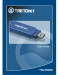
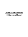
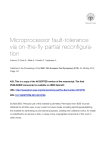
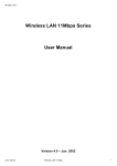
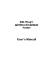
1
Federal Communication Commission Interference
Statement
This equipment has been tested and found to comply with the limits for a Class B digital device,
pursuant to Part 15 of the FCC Rules. These limits are designed to provide reasonable protection
against harmful interference in a residential installation. This equipment generates, uses and can
radiate radio frequency energy and, if not installed and used in accordance with the instructions, may
cause harmful interference to radio communications. However, there is no guarantee that
interference will not occur in a particular installation. If this equipment does cause harmful
interference to radio or television reception, which can be determined by turning the equipment off and
on, the user is encouraged to try to correct the interference by one of the following measures:
z
z
z
z
Reorient or relocate the receiving antenna.
Increase the separation between the equipment and receiver.
Connect the equipment into an outlet on a circuit different from that to which the receiver
is connected.
Consult the dealer or an experienced radio/TV technician for help.
FCC Caution: Any changes or modifications not expressly approved by the party responsible for
compliance could void the user's authority to operate this equipment.
This device complies with Part 15 of the FCC Rules. Operation is subject to the following two
conditions: (1) This device may not cause harmful interference, and (2) this device must accept any
interference received, including interference that may cause undesired operation.
IMPORTANT NOTE:
FCC Radiation Exposure Statement:
This equipment complies with FCC radiation exposure limits set forth for an uncontrolled
environment.
This device complies with FCC RF Exposure limits set forth for an uncontrolled environment,
under 47 CFR 2.1093 paragraph (d)(2).
This transmitter must not be co-located or operating in conjunction with any other antenna or
transmitter.
This device was tested for typical by stander conditions that may occur during use. To comply
with FCC RF exposure requirements a minimum separation distance of 1.5cm must be
maintained between the user’s body and the device, including the antenna.
CE Mark Warning
This is a Class B product. In a domestic environment, this product may cause radio interference, in
which case the user may be required to take adequate measures.
This transmitter must not be co-located or operation in conjunction with any other antenna or
transmitter.
2
Table of Contents
Federal Communications Commission (FCC) Interference statement
CE Mark Warning
2
2
Chapter 1 – Wireless LAN Networking
Transmission Rate
Type of Wireless Networks
Ad-Hoc (IBSS) Network
Infrastructure (BSS) Network
Wireless LAN Security
Data Encryption with WEP
4
4
5
5
7
7
Chapter 2 - Getting Started
About Your 802.11b/g Wireless USB2.0 Adapter
Package Content
System Requirement
Wireless Utility and Adapter Hardware Installation
Using the Utility to Configure Your Network
Link Information
Site Survey
Profile
8
8
8
9
12
13
14
15
Chapter 3 – HotSpot Features
Charging the TEW-509UB
Identifying Components
LCD Display
Finding a HotSpot
Accessing a HotSpot
Chapter 4 – Maintenance
Uninstalling the Driver
Uninstall the Client Utility
Upgrading the Wireless Utility
22
22
22
Glossary
23
20
20
21
21
21
Rev. 1.1
3
Chapter 1- Wireless LAN Networking
This section provides background information on wireless LAN networking technology.
THE INFORMATION IN THIS SECTION IS FOR YOUR REFERENCE. CHANGING
NETWORK SETTINGS AND PARTICULARLY SECURITY SETTTINGS SHOULD
ONLY BE DONE BY AN AUTHORIZED ADMINISTRATOR.
Transmission Rate (Transfer Rate)
The adapter provides various transmission (data) rate options for you to select. Options
include Fully Auto, 1 Mbps, 2 Mbps, 5.5 Mbps, 11 Mbps, 6 Mbps, 9 Mbps, 12 Mbps, 18 Mbps,
22 Mbps, 24 Mbps, 36 Mbps, 48 Mbps, and 54Mbps. In most networking scenarios, the
factory default Fully Auto setting proves the most efficient. This setting allows your adapter
to operate at the maximum transmission (data) rate. When the communication quality drops
below a certain level, the adapter automatically switches to a lower transmission (data) rate.
Transmission at lower data speeds is usually more reliable. However, when the
communication quality improves again, the adapter gradually increases the transmission (data)
rate again until it reaches the highest available transmission rate.
Types of Wireless Networks
Wireless LAN networking works in either of the two modes: ad-hoc and infrastructure. In
infrastructure mode, wireless devices communicate to a wired LAN via access points. Each
access point and its wireless devices are known as a Basic Service Set (BSS). An Extended
Service Set (ESS) is two or more BSSs in the same subnet. In ad hoc mode (also known as
peer-to-peer mode), wireless devices communicate with each other directly and do not use
an access point. This is an Independent BSS (IBSS).
To connect to a wired network within a coverage area using access points, set the adapter
operation mode to Infrastructure (BSS). To set up an independent wireless workgroup without
an access point, use Ad-hoc (IBSS) mode.
A D -H OC (IBSS) N ETWORK
Ad-hoc mode does not require an access point or a wired network. Two or more wireless
stations communicate directly to each other. An ad-hoc network may sometimes be referred
to as an Independent Basic Service Set (IBSS).
To set up an ad-hoc network, configure all the stations in ad-hoc mode. Use the same SSID
and channel for each client.
4
When a number of wireless stations are connected using a single access point, you have a
Basic Service Set (BSS).
5
In the ESS diagram below, communication is done through the access points, which relay
data packets to other wireless stations or devices connected to the wired network. Wireless
stations can then access resources, such as a printer, on the wired network.
In an ESS environment, users are able to move from one access point to another without
losing the connection. In the diagram below, when the user moves from BSS (1) to BSS (2)
the adapter automatically switches to the channel used in BSS (2).
Roaming in an ESS network diagram
6
W IRELESS LAN S ECURITY
Because wireless networks are not as secure as wired networks, it is vital that security
settings are clearly understood and applied.
The list below shows the possible wireless security levels on your adapter starting with the
most secure. EAP (Extensible Authentication Protocol) is used for authentication and utilizes
dynamic WEP key exchange. EAP requires interaction with a RADIUS (Remote
Authentication Dial-In User Service) server either on the WAN or the LAN to provide
authentication service for wireless stations.
1.
Wi-Fi Protected Access (WPA)
2.
IEEE802.1X EAP with RADIUS Server Authentication
3.
WEP Encryption
4.
Unique ESSID
D ATA E NCRYPTION WITH W E P
The WEP (Wired Equivalent Privacy) security protocol is an encryption method designed to try
to make wireless networks as secure as wired networks. WEP encryption scrambles all data
packets transmitted between the adapter and the access point or other wireless stations to
keep network communications private. Both the wireless stations and the access points must
use the same WEP key for data encryption and decryption.
DO NOT ATTEMPT TO CONFIGURE OR CHANGE SECURITY SETTTINGS FOR A
NETWORK WITHOUT AUTHORIZATION AND WITHOUT CLEARLY UNDERSTANDING
THE SETTINGS YOU ARE APPLING. WITH POOR SECURITY SETTINGS, SENSITIVE
DATA YOU SEND CAN BE SEEN BY OTHERS.
There are two ways to create WEP keys in your adapter.
•
Automatic WEP key generation based on a password phrase called a passphrase.
The passphrase is case sensitive. You must use the same passphrase for all WLAN
adapters with this feature in the same WLAN.
•
For WLAN adapters without the passphrase feature, you can still take advantage of
this feature by writing down the four automatically generated WEP keys from the
Security Settings screen of the wireless utility and entering them manually as the WEP
keys in the other WLAN adapter(s).
The adapter allows you to configure up to four WEP keys and only one key is used as the
default transmit key at any one time.
THE adapter supports 64-BIT, 128-BIT, or 152-BIT WEP Encryptions. THE 152-BIT WEP MUST
COMPLY WITH THE WEP SETTING OF YOUR ACCESS POINT OR ROUTER.
7
Chapter 2 - Getting Started
This chapter introduces the Adapter and prepares you to use the Wireless Utility.
2.1
About Your 802.11a/b/g Wireless USB2.0 Adapter with HotSpot
Detector
The Adapter is an 802.11a, 802.11b, and 802.11g compliant wireless LAN adapter. With the Adapter,
you can enjoy wireless mobility within almost any wireless networking environment.
The following lists the main features of your Adapter.
9
Your Adapter can communicate with other IEEE 802.11a/b/g compliant wireless devices.
9
Automatic rate selection.
9
Standard data transmission rates up to 54 Mbps
9
Offers 64-bit, 128-bit and 152-bit WEP (Wired Equivalent Privacy) data encryption for
network security.
9
Supports IEEE802.1x and WPA (Wi-Fi Protected Access).
9
Low CPU utilization allowing more computer system resources for other programs.
9
A built-in antenna.
9
Driver support for Windows Win98SE/ME/2000/XP/2003 Server
2.2
Package Content
¾
¾
¾
2.3
54Mbps 802.11a/g Wireless USB 2.0 Adapter with HotSpot Detector
Driver/Utility CD-ROM
Multi-Language Quick Installation Guide
System Requirement
z
z
z
Pentium class notebook computers with at least one available USB port
Microsoft Windows 98SE/ME/2000/XP/2003
CD-ROM drive
8
2.4
Wireless Utility & Adapter Hardware Installation
NOTE: Please do not connect the USB adapter unless instructed to do so
Follow the instructions below to install the USB Adapter and Utility.
STEP 1
Insert the Driver and Utility CD into CD drive
STEP 2
Autorun window appears automatically, click on Install Utility button to start.
STEP 3
The InstallShield Wizard prepares for installation.
STEP 4
The InstallShield Wizard prompts you for confirmation. Click Next on the following menu.
9
STEP 5
In the destination Folder screen you are asked to confirm the Destination Folder for the application
software. Click Next to continue.
STEP 6
The wizard is ready to begin installation. Click Install to start the installation.
10
STEP 7
Click Finish to complete the client utility installation.
STEP 8
At this moment please insert your USB Adapter to your Laptop, Choose Install the software
automatically and click Next.
STEP 9
Click Finish to complete the installation.
11
2.6 Using the Utility to Configure Your Network
The following are explanations on how to configure and use the Utility program. After completing the
installation procedure, a new icon will automatically appear in the lower right task bar.
Hold your mouse pointer over the icon, and press the right mouse button to open the Wireless Client
Utility.
The Wireless Client Utility window as shown below will appear.
The user can now use any of the management functions available in the IEEE 802.11 Wireless Client
Utility.
12
2.6.1 Link Information
Click the Link Information tab to see general information about the program and its operations. The
Link Information tab does not require any configuration.
The following table describes the items found on the Link Information screen.
Wireless Network Status
Profile Name The name of the current selected configuration profile. Set up the
configuration name on the Profile tab.
SSID Displays the wireless network name.
Link Status Shows whether the station is associated to the wireless network.
Network Type
Infrastructure (access point)
Ad Hoc
Wireless Mode Displays the wireless mode. 802.11a or 11b or 11g
Channel
Shows the currently connected channel.
Transmit Rate Displays the current transmit rate in Mbps.
AP MAC Address Displays the MAC address of the access point the wireless adapter is
associated to.
Signal Strength Shows the strength of the signal.
Security Status
Security Shows the security type – Disable, WEP, WPA/WPA2,
WAP-PSK/WAP2-PSK or 802.1X
Authentication Displays the authentication mode.
TCP/IP Status
IP Address Displays the computer's IP address.
Subnet Mask
Gateway
Displays subnet mask
Displays gateway address
DNS Server Display DNS server address
13
2.6.2 Site Survey
Click the Site Survey tab to see available infrastructure and ad hoc networks.
On this screen, click Refresh to refresh the list at any time.
Connecting to a different network
Hold your mouse pointer over the network icon, and click the right mouse button to select the network.
Click the Connect button to connect the available network. If no configuration profile exists for that
network, the Profile Settings window opens to ask to create a profile for the network. Follow the
procedures to create profile for that network.
14
2.6.3 Profile
To add a new configuration profile, click Add on the Profile tab.
To modify a configuration profile, select the configuration from the Profile list and click the Edit button.
15
Scan Available Networks
Click the Browse button on the Profile Settings screen to scan for available infrastructure and ad hoc
networks. On this list, click Refresh to refresh the list at any time.
To configure a profile for Ad-Hoc or Infrastructure mode, select the Network Type field on the Profile
Settings.
Click Next to continue the profile setting.
To define the security mode, select the security button of the desired security mode. And then click
Next to continue. Please see following table for details of security modes.
16
WPA/WPA2 Enables the use of Wi-Fi Protected Access (WPA).
Choosing WPA/WPA2 opens the WPA/WPA2 Security Settings
screen. The options include:
TLS (Transport Layer Security) is a Point-to-Point Protocol
(PPP) extension supporting additional authentication methods
within PPP. Transport Layer Security (TLS) provides for mutual
authentication, integrity-protected cipher suite negotiation, and key
exchange between two endpoints.
PEAP (EAP-GTC) (Protected Extensible Authentication
Protocol) authenticates wireless LAN clients using only
server-side digital certificates by creating an encrypted SSL/TLS
tunnel between the client and the authentication server. The tunnel
then protects the subsequent user authentication exchange.
PEAP (EAP-MSCHAP V2) (Protected Extensible
Authentication Protocol) To use PEAP (EAP-MSCHAP V2)
security, the server must have WPA-PEAP certificates, and
the server properties must already be set. Check with the IT
manager
TTLS (Tunneled Transport Layer Security) An EAP variant that
provides mutual authentication using a certificate for server
authentication, and via a secure TLS tunnel for the client
LEAP (Lightweight and Efficient Application Protocol)
is the general framework for a set of high-performance,
efficient protocols which are ideal for mobile and wireless
applications. LEAP is designed to address all the technical
requirements of the wireless data communications industry,
and is oriented towards providing the greatest benefit to the
industry and the consumer
WPA-PSK/WPA2-PSK Enables WPA/WPA2 Passphrase security.
Fill in the WPA/WPA2 Passphrase on Security Settings screen.
802.1x Enables 802.1x security. This option requires IT administration.
Choosing 802.1x opens the 802.1x Security Settings screen. The
options include:
TLS / PEAP /TTLS / LEAP
17
Advanced Settings
After Security Settings finished, the Advanced Settings screen will be shown as following.
The following table describes the items found on the Advanced Settings screen.
Power Save Mode
Shows the power save mode. Power management is disabled in ad
hoc mode. The options include:
z
Continuous Access Mode
z
Maximum Power Saving
z
Fast Power Saving
802.11b Preamble Displays the 802.11b preamble format.
The options include:
z
Long
z
Short
z
Auto
RTS Threshold Value from 0 ~ 2347
FRAG Threshold Value from 256 ~ 2346
Wireless Mode Include:
z
802.11a
z
802.11b
z
802.11g
18
After advance settings are finished, the following screen showed as below.
You can activate the profile now or later.
19
Chapter 3 – HotSpot
This section explains the hardware section of the TEW-509UB.
3.1
Charging the TEW-509UB
The TEW-509UB is powered by a rechargeable battery. The battery must be charged before
first use as follows.
CAUTION
Most notebook computer USB connectors are
horizontal. The TEW-509UB should be connected with
the display facing up. If the USB connector on your
computer is vertical, connect the TEW-509UB carefully
to avoid damaging the connectors.
1. Remove the cap from the
TEW-509UB.
2. With the display facing up,
insert the TEW-509UB into a
USB connector on your
computer.
The
icon on the LCD
screen indicating the battery
is charging.
3.2
Identifying Components
The illustration below shows the buttons and LEDs on the TEW-509UB.
Next
Seek
Seek LED
Power
Power LED
20
3.3
LCD Display
The illustration below shows the icons in the LCD. All the icons will not necessarily appear
together as shown here.
3
4
5
6
7
2
1
1 SSID:
2 Channel:
3 Found:
4 Power:
5 Scan mode:
6 Security
7 Signal
Strength
Displays the SSID of the current connection. Scrolls
horizontally for longer names.
Displays the channel number of the current
connection.
Displays the number of connections found. Up to 16
connections can be monitored.
Indicates the battery status:
low;
fully charged;
recharging.
Press and hold the Seek button to scroll
through the three modes: [S]; [F]; and [D].
Scan results are ranked in order of signal
strength.
Only lists open hot spots ranked in order of
signal strength.
Continually refreshes details of the selected hot
spot. Allows you to lock on and monitor the
signal strength as you move around.
Displays the security settings of the network:
[WEP]/[WPA] security enabled;
security
disabled.
Displays the signal strength (five levels) and
radio band: [G]/[B] 802.11a/b/g.
Fully charged and Recharging icons would appear during charging process only.
3.4
Finding a HotSpot
Refer to the following to find a hot spot.
3. Switch Power to ON. The TEW-509UB boots and searches for hot spots.
4. Press Next to scroll the available hot spots.
3.5
Accessing a HotSpot
5. Connect the TEW-509UB to your computer and open the Wireless Client Utility.
6. Open the SiteSurvey screen and select the hot spot you want to access.
7. Click Connect to access the hot spot.
21
Chapter 4 – Maintenance
This chapter describes how to uninstall or upgrade the Wireless Utility.
4.1 Uninstall the Driver
Follow the steps below to remove (or uninstall) the USB Adapter driver from your computer.
Step 1. To remove the driver from the OS, go to Start -> Control Panel
Step 2.
Double-click System
Step 3.
Under Hardware tab, click Device Manager.
Step 4.
Double-click Network Adapter
Step 5.
Right-click mouse button on “54Mbps 802.11g Wireless LAN”, and choose Uninstall
Step 6.
Click OK to confirm that you are going to uninstall the driver
4.2 Uninstall the Client Utility
Follow the steps below to remove the Client Utility from your computer.
Step 1. To remove the utility from the OS, go to Start -> Control Panel
Step 2.
Double-click Add-Remove Programs
Step 3.
Select TEW-509UB Wireless Client Utility, and click the Remove button
4.3 Upgrading the Wireless Utility
To perform the upgrade, follow the steps below.
Step 1. Download the latest version of the utility from the web site and save the file on your
computer.
Step 2.
Follow the steps in Section 2.2 to remove the current Wireless Utility from your computer.
Step 3.
Restart your computer if prompted.
Step 4.
After restarting, refer to the procedure in the Chapter 2 to install the new utility.
22
Glossary
For unfamiliar terms used below, look for entries elsewhere in the glossary.
AD-HOC (IBSS)
Ad-hoc mode does not require an AP or a wired network. A network that transmits
wireless from computer to computer without the use of a base station (access point).
Two or more wireless stations communicate directly to each other. An ad-hoc network
may sometimes be referred to as an Independent Basic Service Set (IBSS).
CHANNEL
A radio frequency used by a wireless device is called a channel.
EAP AUTHENTICATION
EAP (Extensible Authentication Protocol) is an authentication protocol that runs on top of
the IEEE802.1X transport mechanism in order to support multiple types of user
authentication. By using EAP to interact with an EAP-compatible RADIUS server, an
access point helps a wireless station and a RADIUS server perform authentication.
ENCRYPTION
The reversible transformation of data from the original to a difficult-to-interpret format.
Encryption is a mechanism for protecting confidentiality, integrity, and authenticity of data.
It uses an encryption algorithm and one or more encryption keys.
FRAGMENTATION THRESHOLD
This is the maximum data fragment size that can be sent before the packet is fragmented
into smaller packets.
IEEE 802.1X
The IEEE 802.1X standard outlines enhanced security methods for both the authentication
of wireless stations and encryption key management. Authentication can be done using an
external RADIUS server.
INFRASTRUCTURE (BSS)
When a number of wireless stations are connected using a single AP, you have a Basic
Service Set (BSS).
23
ROAMING
In an infrastructure network, wireless stations are able to switch from one BSS to another
as they move between the coverage areas. During this period, the wireless stations
maintain uninterrupted connection to the network. This is roaming. As the wireless station
moves from place to place, it is responsible for choosing the most appropriate AP
depending on the signal strength, network utilization among other factors.
SSID
The SSID (Service Set Identity) is a unique name shared among all wireless devices in a
wireless network. Wireless devices must have the same SSID to communicate with each
other.
TEMPORAL KEY INTEGRITY PROTOCOL (TKIP)
Temporal Key Integrity Protocol (TKIP) uses 128-bit keys that are dynamically generated and
distributed by the authentication server.
USER AUTHENTICATION
WPA applies IEEE 802.1X and Extensible Authentication Protocol (EAP) to authenticate
wireless clients using an external RADIUS database. If you do not have an external RADIUS
server, use WPA-PSK/WPA2-PSK (WPA -Pre-Shared Key) that only requires a single (identical) password entered into each access point, wireless gateway and wireless client. As long
as the passwords match, clients will be granted access to a WLAN.
WEP
WEP (Wired Equivalent Privacy) encryption scrambles all data packets transmitted between
the WCB-321A and the AP or other wireless stations to keep network communications private. Both the wireless stations and the access points must use the same WEP key for data
encryption and decryption.
WPA/WPA2
Wi-Fi Protected Access (WPA) and WPA2 (future upgrade) is a subset of the IEEE 802.11
i security specification draft. Key differences between WPA and WEP are user
authentication and improved data encryption. WPA2 is a wireless security standard that
defines stronger encryption, authentication and key management than WPA.
24
Limited Warranty
TRENDware warrants its products against defects in material and workmanship, under normal use and
service, for the following lengths of time from the date of purchase.
Wireless Products – 3 Years Warranty
If a product does not operate as warranted above during the applicable warranty period, TRENDware
shall, at its option and expense, repair the defective product or part, deliver to customer an equivalent
product or part to replace the defective item, or refund to customer the purchase price paid for the
defective product. All products that are replaced will become the property of TRENDware.
Replacement products may be new or reconditioned.
TRENDware shall not be responsible for any software, firmware, information, or memory data of
customer contained in, stored on, or integrated with any products returned to TRENDware pursuant to
any warranty.
There are no user serviceable parts inside the product. Do not remove or attempt to service the
product by any unauthorized service center. This warranty is voided if (i) the product has been
modified or repaired by any unauthorized service center, (ii) the product was subject to accident,
abuse, or improper use (iii) the product was subject to conditions more severe than those specified in
the manual.
Warranty service may be obtained by contacting TRENDware office within the applicable warranty
period for a Return Material Authorization (RMA) number, accompanied by a copy of the dated proof of
the purchase. Products returned to TRENDware must be pre-authorized by TRENDware with RMA
number marked on the outside of the package, and sent prepaid, insured and packaged appropriately
for safe shipment.
WARRANTIES EXCLUSIVE: IF THE TRENDWARE PRODUCT DOES NOT OPERATE AS
WARRANTED ABOVE, THE CUSTOMER’S SOLE REMEDY SHALL BE, AT TRENDWARE’S OPTION,
REPAIR OR REPLACEMENT. THE FOREGOING WARRANTIES AND REMEDIES ARE EXCLUSIVE
AND ARE IN LIEU OF ALL OTHER WARRANTIES, EXPRESSED OR IMPLIED, EITHER IN FACT OR
BY OPERATION OF LAW, STATUTORY OR OTHERWISE, INCLUDING WARRANTIES OF
MERCHANTABILITY AND FITNESS FOR A PARTICULAR PURPOSE. TRENDWARE NEITHER
ASSUMES NOR AUTHORIZES ANY OTHER PERSON TO ASSUME FOR IT ANY OTHER LIABILITY
IN CONNECTION WITH THE SALE, INSTALLATION MAINTENANCE OR USE OF TRENDWARE’S
PRODUCTS.
TRENDWARE SHALL NOT BE LIABLE UNDER THIS WARRANTY IF ITS TESTING AND
EXAMINATION DISCLOSE THAT THE ALLEGED DEFECT IN THE PRODUCT DOES NOT EXIST
OR WAS CAUSED BY CUSTOMER’S OR ANY THIRD PERSON’S MISUSE, NEGLECT, IMPROPER
INSTALLATION OR TESTING, UNAUTHORIZED ATTEMPTS TO REPAIR OR MODIFY, OR ANY
OTHER CAUSE BEYOND THE RANGE OF THE INTENDED USE, OR BY ACCIDENT, FIRE,
LIGHTNING, OR OTHER HAZARD.
LIMITATION OF LIABILITY: TO THE FULL EXTENT ALLOWED BY LAW TRENDWARE ALSO
EXCLUDES FOR ITSELF AND ITS SUPPLIERS ANY LIABILITY, WHETHER BASED IN CONTRACT
OR TORT (INCLUDING NEGLIGENCE), FOR INCIDENTAL, CONSEQUENTIAL, INDIRECT,
SPECIAL, OR PUNITIVE DAMAGES OF ANY KIND, OR FOR LOSS OF REVENUE OR PROFITS,
LOSS OF BUSINESS, LOSS OF INFORMATION OR DATE, OR OTHER FINANCIAL LOSS ARISING
OUT OF OR IN CONNECTION WITH THE SALE, INSTALLATION, MAINTENANCE, USE,
PERFORMANCE, FAILURE, OR INTERRUPTION OF THE POSSIBILITY OF SUCH DAMAGES, AND
LIMITS ITS LIABILITY TO REPAIR, REPLACEMENT, OR REFUND OF THE PURCHASE PRICE
PAID, AT TRENDWARE’S OPTION. THIS DISCLAIMER OF LIABILITY FOR DAMAGES WILL NOT
BE AFFECTED IF ANY REMEDY PROVIDED HEREIN SHALL FAIL OF ITS ESSENTIAL PURPOSE.
Governing Law: This Limited Warranty shall be governed by the laws of the state of California.
AC/DC Power Adapter, Cooling Fan, and Power Supply carry 1 Year Warranty
25
26