1
Table of Contents
CHAPTER 1 INTRODUCTION ............................................................................................. 1
Broadband VPN Gateway Features ................................................................................ 1
Package Contents .............................................................................................................. 3
Physical Details .................................................................................................................. 4
CHAPTER 2 INSTALLATION ............................................................................................... 6
Requirements ..................................................................................................................... 6
Procedure ........................................................................................................................... 6
CHAPTER 3 SETUP ................................................................................................................ 8
Overview ............................................................................................................................ 8
Configuration Program .................................................................................................... 9
WAN Port Configuration ............................................................................................... 12
Port Options Screen ........................................................................................................ 14
LAN Port Screen ............................................................................................................. 16
Load/Backup Screen ....................................................................................................... 18
CHAPTER 4 PC CONFIGURATION .................................................................................. 20
Overview .......................................................................................................................... 20
Windows Clients .............................................................................................................. 20
Macintosh Clients ............................................................................................................ 33
Linux Clients .................................................................................................................... 33
Other Unix Systems ......................................................................................................... 33
CHAPTER 5 OPERATION AND STATUS ......................................................................... 34
Operation ......................................................................................................................... 34
Status Screen .................................................................................................................... 34
Port Status........................................................................................................................ 37
Event Log ......................................................................................................................... 38
URL Log ........................................................................................................................... 39
System Log ....................................................................................................................... 40
CHAPTER 6 INTERNET FEATURES ................................................................................ 41
Overview .......................................................................................................................... 41
Address List ..................................................................................................................... 42
PC Database ..................................................................................................................... 43
URL Filter ........................................................................................................................ 45
Dynamic DNS................................................................................................................... 47
Static Routing .................................................................................................................. 49
QoS ................................................................................................................................... 54
CHAPTER 7 SECURITY CONFIGURATION ................................................................... 56
Overview .......................................................................................................................... 56
Rules ................................................................................................................................. 56
Schedules .......................................................................................................................... 60
Firewall -- Log ................................................................................................................. 61
Services ............................................................................................................................. 63
Security............................................................................................................................. 65
DMZ ................................................................................................................................. 67
E-Mail ............................................................................................................................... 68
CHAPTER 8 VPN (IPSEC).................................................................................................... 70
Overview .......................................................................................................................... 70
Common VPN Situations ................................................................................................ 72
VPN Configuration ......................................................................................................... 74
i
VPN Examples ................................................................................................................. 82
Certificates ..................................................................................................................... 100
CRL ................................................................................................................................ 104
VPN Status ..................................................................................................................... 105
Add Certificate .................................................................... Error! Bookmark not defined.
Get Certificate ID ................................................................ Error! Bookmark not defined.
CHAPTER 9 MICROSOFT VPN ....................................................................................... 106
Overview ........................................................................................................................ 106
Server Setup ................................................................................................................... 106
User ................................................................................................................................. 107
Status Log Screen .......................................................................................................... 109
Windows Client Setup ................................................................................................... 110
CHAPTER 10 OTHER FEATURES & SETTINGS ......................................................... 118
Overview ........................................................................................................................ 118
Diagnostics ..................................................................................................................... 119
Password Screen ............................................................................................................ 121
Web Management ......................................................................................................... 122
Firmware Upgrade ........................................................................................................ 124
Backup/Restore.............................................................................................................. 125
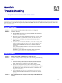
APPENDIX A TROUBLESHOOTING .............................................................................. 127
Overview ........................................................................................................................ 127
General Problems .......................................................................................................... 127
Internet Access............................................................................................................... 127
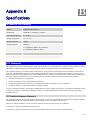
APPENDIX B SPECIFICATIONS...................................................................................... 129
Broadband VPN Gateway ............................................................................................ 129
FCC Statement .............................................................................................................. 129
CE Marking Warning ................................................................................................... 130
P/N: 956YH10001
Copyright © 2007. All Rights Reserved.
Document Version:1.0
All trademarks and trade names are the properties of their respective owners.
ii
1
Chapter 1
Introduction
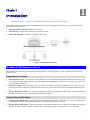
This Chapter provides an overview of the Broadband VPN Gateway's features and capabilities.
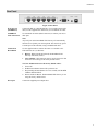
Congratulations on the purchase of your new Broadband VPN Gateway. The Broadband VPN Gateway is a multi-function device
providing the following services:
•
•
•
Shared Broadband Internet Access for all LAN users.
VPN Gateway for IPSec VPN connections to remote PCs or sites.
4-Port Switching Hub for 10BaseT or 100BaseT connections.
Figure 1: Broadband VPN Gateway
Broadband VPN Gateway Features
The Broadband VPN Gateway incorporates many advanced features, carefully designed to provide sophisticated functions while
being easy to use.
Internet Access Features
•
Shared Internet Access. All users on the LAN or WLAN can access the Internet through the Broadband VPN Gateway, using
only a single external IP Address. The local (invalid) IP Addresses are hidden from external sources. This process is called NAT
(Network Address Translation).
•
Dual WAN Support. Dual 10/100 WAN ports let you have a second link to your ISP, providing failover protection. You can
use both WAN ports simultaneously, and let the router balance the requirements between them for maximum bandwidth efficiency.
•
Fixed or Dynamic IP Address. On the Internet (WAN port) connection, the Broadband VPN Gateway supports both Dynamic
IP Address (IP Address is allocated on connection) and Fixed IP Address.
Advanced Internet Functions
•
Communication Applications. Support for Internet communication applications, such as interactive Games, Telephony, and
Conferencing applications, which are often difficult to use when behind a Firewall, is included.
•
Special Internet Applications. Applications which use non-standard connections or port numbers are normally blocked by the
Firewall. The ability to define and allow such applications is provided, to enable such applications to be used normally.
1
Broadband VPN Gateway User Guide
•
Virtual Servers. This feature allows Internet users to access Internet servers on your LAN. The required setup is quick and
easy.
•
Multi-DMZ. For each WAN (Internet) IP address allocated to you, one (1) PC on your local LAN can be configured to allow
unrestricted 2-way communication with Servers or individual users on the Internet. This provides the ability to run programs
which are incompatible with Firewalls.
•
•
Address List. Use address list to block access to undesirable Web sites by LAN users. Up to 40 addresses can be listed.
IM/P2P Control. The IM/P2P control allows you to better manage your employees’ network activities and prevent possible
misuse of IM and P2P applications.
•
•
•
URL Filter. Use the URL Filter to block access to undesirable Web sites by LAN users.
Internet Access Log. See which Internet connections have been made.
VPN Pass through Support. PCs with VPN (Virtual Private Networking) software using PPTP, L2TP and IPSec are transparently supported - no configuration is required.
•
QoS Support Quality of Service can be used to handle packets so that more important connections receive priority over less
important one.
LAN Features
•
4-Port Switching Hub. The Broadband VPN Gateway incorporates a 4-port 10/100BaseT switching hub, making it easy to
create or extend your LAN.
•
DHCP Server Support. Dynamic Host Configuration Protocol provides a dynamic IP address to PCs and other devices upon
request. The Broadband VPN Gateway can act as a DHCP Server for devices on your local LAN and WLAN.
Configuration & Management
•
•
Easy Setup. Use your WEB browser from anywhere on the LAN or WLAN for configuration.
Remote Management. The Broadband VPN Gateway can be managed from any PC on your LAN. And, if the Internet connection exists, it can also (optionally) be configured via the Internet.
•
UPnP Support. UPnP (Universal Plug and Play) allows automatic discovery and configuration of the Broadband VPN Gateway. UPnP is by supported by Windows ME, XP, or later.
•
Multi-Language Support. Multi-Language Pack facilitates the process of creating multi-language applications. Add support
for as many languages as you like.
•
Configuration File Backup & Restore. You can backup (download) the Broadband VPN Gateway's configuration file to
your PC, and restore (upload) a previously-saved configuration file to the Broadband VPN Gateway.
2
Introduction
Security Features
•
Password - protected Configuration. Optional password protection is provided to prevent unauthorized users from modifying
the configuration data and settings.
•
NAT Protection. An intrinsic side effect of NAT (Network Address Translation) technology is that by allowing all LAN users
to share a single IP address, the location and even the existence of each PC is hidden. From the external viewpoint, there is no
network, only a single device - the Broadband VPN Gateway.
•
NATT (NAT-Traversal). NAT Traversal is a method to allow IPSec to work through NAT devices. It is encapsulating IPsec
ESP packets into UDP packets for passing through routers or firewalls employing Network Address Translation (NAT).
•
Stateful Inspection Firewall. All incoming data packets are monitored and all incoming server requests are filtered, thus
protecting your network from malicious attacks from external sources.
•
•
IP/MAC Binding. Users cannot change the IP address unless they have the permission of the IT manager.
Protection against DoS attacks. DoS (Denial of Service) attacks can flood your Internet connection with invalid packets and
connection requests, using so much bandwidth and so many resources that Internet access becomes unavailable. The Broadband
VPN Gateway incorporates protection against DoS attacks.
•
Rule-based Policy Firewall. To provide additional protection against malicious packets, you can define your own firewall
rules. This can also be used to control the Internet services available to LAN users.
IPSec VPN Gateway Features
•
•
•
•
IPSec. Support for IPSec standards, including IKE and certificates.
100 Tunnels. Up to 100 VPN tunnels can be created.
High performance. High performance encryption engine maintains high throughput even when using 3DES.
DPD Support Dead Peer Detection is a method of detecting a dead Internet Key Exchange (IKE) peer. The method uses IPSec
traffic patterns to minimize the number of messages required to confirm the liveness of a peer. DPD is used to reclaim the lost resources in case a peer is found dead.
Microsoft VPN Gateway Support
•
PPTP Server. The Broadband VPN Gateway emulates a Microsoft PPTP VPN Server, allowing clients to use the Microsoft
VPN client provided in Windows.
•
Windows Client Support. Remote users can use the Microsoft VPN client (VPN Adapter) provided in recent versions of
Windows.
•
Easy Setup. For both the Administrator and remote users, the Microsoft VPN is much easier to configure than IPSec VPN.
Package Contents
The following items should be included:
•
The Broadband VPN Gateway Unit
•
Power Adapter
•
Quick Installation Guide
•
CD-ROM containing the on-line manual.
If any of the above items are damaged or missing, please contact your dealer immediately.
3
Broadband VPN Gateway User Guide
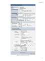
Physical Details
Front-mounted LEDs
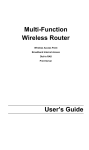
Figure 2: Front Panel
Power
On - Power on.
Off - No power.
Status (Red)
On - Error condition.
Off - Normal operation.
Blinking - This LED blinks during start up.
WAN ports
(10/100BaseT)
Connect the DSL or Cable Modem here. If your modem came with a
cable, use the supplied cable. Otherwise, use a standard LAN cable.
LAN
Each port has 2 LEDs
•
•
WLAN LED
Link/Act
•
On - Corresponding LAN (hub) port is active.
•
Off - No active connection on the corresponding LAN (hub)
port.
•
Flashing - Data is being transmitted or received via the corresponding LAN (hub) port.
100
•
On - Corresponding LAN (hub) port is using 100BaseT.
•
Off - Corresponding LAN (hub) port connection is using
10BaseT, or no active connection.
On - Wireless enabled.
Off - No Wireless connections currently exist.
Flashing - Data is being transmitted or received via the Wireless access
point. This includes "network traffic" as well as user data.
4
Introduction
Rear Panel
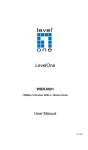
Figure 3: Rear Panel
WAN port 1/2
(10/100BaseT)
Connect the DSL or Cable Modem here. If your modem came with a
cable, use the supplied cable. Otherwise, use a standard LAN cable.
10/100BaseT
LAN connections
Use standard LAN cables (RJ45 connectors) to connect your PCs to
these ports.
Note:
Any LAN port on the Broadband VPN Gateway will automatically
function as an "Uplink" port when required. Just connect any port to
a normal port on the other hub, using a standard LAN cable.
Console Port
Use the supplied cable to connect the router to a terminal or PC.
Reset Button
This button has two (2) functions:
•
Reboot. When pressed and released, the Broadband VPN
Gateway will reboot (restart).
•
Clear All Data. This button can also be used to clear ALL data
and restore ALL settings to the factory default values.
To Clear All Data and restore the factory default values:
1. Power Off.
2. Hold the Reset Button down while you Power On.
3. Keep holding the Reset Button for a few seconds, until the RED
LED has flashed TWICE.
4. Release the Reset Button. The Broadband VPN Gateway is now
using the factory default values.
Power port
Connect the supplied power adapter here.
5
2
Chapter 2
Installation
This Chapter covers the physical installation of the Broadband VPN Gateway.
Requirements
•
Network cables. Use standard 10/100BaseT network (UTP) cables with RJ45 connectors.
•
TCP/IP protocol must be installed on all PCs.
•
For Internet Access, an Internet Access account with an ISP, and a Broadband modem (usually, DSL or Cable modem).
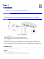
Procedure
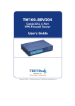
Figure 4: Installation Diagram
1. Choose an Installation Site
Select a suitable place on the network to install the Broadband VPN Gateway.
Ensure the Broadband VPN Gateway and the DSL/Cable modem are powered OFF.
2. Connect LAN Cables
•
Use standard LAN cables to connect PCs to the Switching Hub ports on the Broadband VPN Gateway. Both 10BaseT and
100BaseT connections can be used simultaneously.
•
If required, you can connect any LAN port to another Hub. Any LAN port on the Broadband VPN Gateway will automatically
function as an "Uplink" port when required. Just connect any LAN port to a normal port on the other hub, using a standard LAN
cable.
3. Connect WAN Cable
Connect the Broadband modem to the WAN port on the Broadband VPN Gateway. Use the cable supplied with your Broadband
modem. If no cable was supplied, use a standard LAN cable.
4. Power Up
•
Power on the Broadband modem.
•
Connect the supplied power adapter to the Broadband VPN Gateway and power up.
Use only the power adapter provided. Using a different one may cause hardware damage.
6
Installation
5. Check the LEDs
•
The Power LED should be ON.
•
The Status LED should blink during start up, then turn Off. If it stays on, there is a hardware error.
•
For each LAN (PC) connection, the LAN Link/Act LED should be ON (provided the PC is also ON.)
•
The WAN1 or WAN2 LED should be ON.
For more information, refer to Front-mounted LEDs in Chapter 1.
7
3
Chapter 3
Setup
This Chapter provides Setup details of the Broadband VPN Gateway.
Overview
This chapter describes the setup procedure for:
•
Internet Access
•
LAN configuration
PCs on your local LAN may also require configuration. For details, see Chapter 4 - PC Configuration.
Other configuration may also be required, depending on which features and functions of the Broadband VPN Gateway you wish to
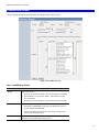
use. Use the table below to locate detailed instructions for the required functions.
To Do this:
Refer to:
Configure PCs on your LAN.
Chapter 4:
PC Configuration
Check Broadband VPN Gateway operation and Status.
Chapter 5:
Operation and Status
Use any of the following Internet features:
Chapter 6:
Internet Features
•
WAN Port
•
Advanced Setup
•
Dynamic DNS
•
Virtual Servers
•
Options
Change any of the following Security-related settings:
•
Admin Login
•
Access Control
•
Firewall Rules
•
Logs
•
E-mail
•
Security Options
•
Scheduling
•
Services
Use the IPSec VPN features:
•
VPN Policies
•
Certificates
•
CRLs
•
VPN Status
Chapter 7:
Security Configuration
Chapter 8:
VPN (IPSec)
8
Setup
Use the Microsoft VPN feature:
•
PPTP Server in the Broadband VPN Gateway.
•
User and Client setup.
•
Checking VPN connection Status.
Configure or use any of the following:
•
Configuration File backup and restore.
•
Network Diagnostic
•
PC Database
•
Remote Administration
•
Routing
•
Upgrade Firmware
•
UPnP
Chapter 9:
Microsoft VPN
Chapter 9:
Other Features and Settings
Where use of a certain feature requires that
PCs or other LAN devices be configured, this
is also explained in the relevant chapter.
Configuration Program
The Broadband VPN Gateway contains an HTTP server. This enables you to connect to it, and configure it, using your Web Browser.
Your Browser must support JavaScript. The configuration program has been tested on the following browsers:
•
Netscape V4.08 or later
•
Internet Explorer V4 or later
Preparation
Before attempting to configure the Broadband VPN Gateway, please ensure that:
•
Your PC can establish a physical connection to the Broadband VPN Gateway. The PC and the Broadband VPN Gateway must be
directly connected (using the Hub ports on the Broadband VPN Gateway) or on the same LAN segment.
•
The Broadband VPN Gateway must be installed and powered ON.
•
If the Broadband VPN Gateway 's default IP Address (192.168.0.1) is already used by another device, the other device must be
turned OFF until the Broadband VPN Gateway is allocated a new IP Address during configuration.
Using UPnP
If your Windows system supports UPnP, an icon for the Broadband VPN Gateway will appear in the system tray, notifying you that a
new network device has been found, and offering to create a new desktop shortcut to the newly-discovered device.
•
Unless you intend to change the IP Address of the Broadband VPN Gateway, you can accept the desktop shortcut.
•
Whether you accept the desktop shortcut or not, you can always find UPnP devices in My Network Places (previously called
Network Neighborhood).
•
Double - click the icon for the Broadband VPN Gateway (either on the Desktop, or in My Network Places) to start the configuration.
Using your Web Browser
To establish a connection from your PC to the Broadband VPN Gateway:
1. After installing the Broadband VPN Gateway in your LAN, start your PC. If your PC is already running, restart it.
2. Start your WEB browser.
9
Broadband VPN Gateway User Guide
3.
In the Address box, enter "HTTP://" and the IP Address of the Broadband VPN Gateway, as in this example, which uses the
Broadband VPN Gateway 's default IP Address:
HTTP://192.168.0.1
If you can't connect
If the Broadband VPN Gateway does not respond, check the following:
•
4.
The Broadband VPN Gateway is properly installed, LAN connection is OK,
and it is powered ON. You can test the connection by using the "Ping" command:
•
Open the MS-DOS window or command prompt window.
•
Enter the command:
ping 192.168.0.1
If no response is received, either the connection is not working, or your
PC's IP address is not compatible with the Broadband VPN Gateway 's IP
Address. (See next item.)
•
If your PC is using a fixed IP Address, its IP Address must be within the range
192.168.0.2 to 192.168.0.254 to be compatible with the Broadband VPN Gateway 's default IP Address of 192.168.0.1. Also, the Network Mask must be
set to 255.255.255.0. See Chapter 4 - PC Configuration for details on checking your PC's TCP/IP settings.
•
Ensure that your PC and the Broadband VPN Gateway are on the same network segment. (If you don't have a router, this must be the case.)
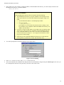
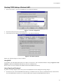
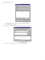
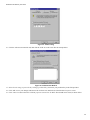
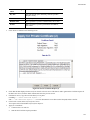
You will be prompted for a username and password, as shown below.
Figure 5: Password Dialog
•
Enter admin for the User Name, and password for the Password.
•
These are the default values. Both the name and password can (and should) be changed, using the Admin Login screen. Once you
have changed either the name or the password, you must use the current values.
10
Setup
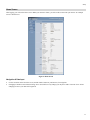
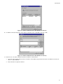
Home Screen
After logging, you will see the Home screen. When you connect in future, you will see this screen when you connect. An example
screen is shown below.
Figure 6: Home Screen
Navigation & Data Input
•
Use the menu bar on the left of the screen, and the "Back" button on your Browser, for navigation.
•
Changing to another screen without clicking "Save" does NOT save any changes you may have made. You must "Save" before
changing screens or your data will be ignored.
11
Broadband VPN Gateway User Guide
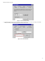
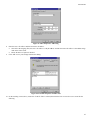
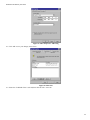
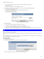
WAN Port Configuration
The WAN Port option is on the Setup menu.
Figure 7: WAN Port Screen
Data - WAN Port Screen
WAN Port Settings
Connections
Normally, this can be left at "Automatic". If the device attached to
the WAN Port has problems making a connection, you can select the
setting required or preferred by the other device.
Connection Type
Select the login method used, and enter the required data.
•
Static IP - Select this if your ISP has allocated you a fixed IP
Address. If this option is selected, you must enter the data in the
Static IP Settings section.
•
Dynamic IP - This is the default, and the most common. Leave
this selected if your ISP allocates an IP Address to the Wireless
Router upon connection.
•
PPPoE - This is the most common login method, widely used
with DSL modems. Normally, your ISP will have provided some
software to connect and login. This software is no longer required, and should not be used.
Static IP Settings
IP Address
The IP Address allocated by the ISP.
Subnet Mask
This is also supplied by your ISP. It must be compatible with the IP
Address above.
12
Setup
Gateway
The address of the router or gateway, as supplied by your ISP.
PPPoE Dial-up
User Name
The User Name (or account name) provided by your ISP.
Password
Enter the password for the login name above.
Hostname
Normally, there is no need to change the default name, but if your
ISP requests that you use a particular Hostname, enter it here.
DNS
DNS 1
Enter the IP address of the DNS (Domain Name Server) you wish to
use.
DNS 2
DNS 2 will be used if the DNS 1 is not available.
Buttons
Save
Save your changes to the Wireless Router.
Cancel
Reverse any changes made since the last "Save".
13
Broadband VPN Gateway User Guide
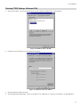
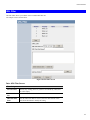
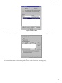
Port Options Screen
Use the Port Options link on the Setup menu. An example screen is shown below.
Figure 8: Port Options Screen
Data - Port Options Screen
Port Options
Symmetric NAT
If Enabled, all requests from the same internal IP address and port to
a specific destination IP address and port are mapped to a unique
external source IP address and port.
Compatible NAT
The default value is Disabled.
Hostname
Normally, there is no need to change the default name, but if your
ISP requests that you use a particular Hostname, enter it here.
Domain Name
If your ISP provided a domain name, enter it here. Otherwise, this
may be left blank.
MAC Address
Also called Network Adapter Address or Physical Address. This is a
low-level identifier, as seen from the WAN port.
Normally there is no need to change this, but some ISPs require a
particular value, often that of the PC initially used for Internet access.
You can use the Clone button to copy your PC's address into this
field, the Default button to insert the default value, or enter a value
directly.
14
Setup
MTU Size
•
MTU (Maximum Transmission Unit) value should only be
changed if advised to do so by Technical Support.
•
Enter a value between 1 and 1500.
•
This device will still auto-negotiate with the remote server, to set
the MTU size. The smaller of the 2 values (auto-negotiated, or
entered here) will be used.
PPPoE Connection
Automatic Dial-up
An Internet connection is automatically made when required, and
disconnected when idle for the time period specified by the "Disconnect after Idling".
Disconnect After
Idling
This field has no effect unless using the Automatic Dial-up setting.
If using this setting, enter the desired idle time-out period (in minutes). After the connection to your ISP has been idle for this time
period, the connection will be terminated.
Bind Service
IPSec Pass
Through
IPSec protocol is used to establish a secure connection, and is widely
used by VPN (Virtual Private Networking) programs.
VPN (PPTP)
PPTP (Point to Point Tunneling Protocol) is widely used by VPN
(Virtual Private Networking) programs.
Network Card
Speed
Select the desired option from the drop-down list.
15
Broadband VPN Gateway User Guide
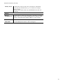
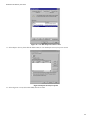
LAN Port Screen
Use the LAN Port link on the main menu to reach the LAN Port screen. An example screen is shown below.
Figure 9: LAN Port Screen
Data - LAN Port Screen
LAN
LAN IP Address
IP address for the Broadband VPN Gateway, as seen from the local
LAN. Use the default value unless the address is already in use or your
LAN is using a different IP address range. In the latter case, enter an
unused IP Address from within the range used by your LAN.
Subnet Mask
The default value 255.255.255.0 is standard for small (class "C")
networks. For other networks, use the Subnet Mask for the LAN
segment to which the Broadband VPN Gateway is attached (the same
value as the PCs on that LAN segment).
DHCP Server
•
If Enabled, the Broadband VPN Gateway will allocate IP Addresses to PCs (DHCP clients) on your LAN when they start up.
The default (and recommended) value is Enabled.
•
If you are already using a DHCP Server, this setting must be
Disabled, and the existing DHCP server must be re-configured to
treat the Broadband VPN Gateway as the default Gateway. See the
following section for further details.
•
The Start IP Address, Number of IP Address Pool, Client Side
DNS and DHCP Lease Time fields set the values used by the
DHCP server when allocating IP Addresses to DHCP clients. This
range also determines the number of DHCP clients supported.
See the following section for further details on using DHCP.
Buttons
Save
Save the data on screen.
Cancel
The "Cancel" button will discard any data you have entered and reload
the file from the Broadband VPN Gateway.
16
Setup
DHCP
What DHCP Does
A DHCP (Dynamic Host Configuration Protocol) Server allocates a valid IP address to a DHCP Client (PC or device) upon request.
•
The client request is made when the client device starts up (boots).
•
The DHCP Server provides the Gateway and DNS addresses to the client, as well as allocating an IP Address.
•
The Broadband VPN Gateway can act as a DHCP server.
•
Windows 95/98/ME and other non-Server versions of Windows will act as a DHCP client. This is the default Windows setting
for the TCP/IP network protocol. However, Windows uses the term Obtain an IP Address automatically instead of "DHCP
Client".
•
You must NOT have two (2) or more DHCP Servers on the same LAN segment. (If your LAN does not have other Routers, this
means there must only be one (1) DHCP Server on your LAN.)
Using the Broadband VPN Gateway 's DHCP Server
This is the default setting. The DHCP Server settings are on the LAN screen. On this screen, you can:
•
Enable or Disable the Broadband VPN Gateway 's DHCP Server function.
•
Set the range of IP Addresses allocated to PCs by the DHCP Server function.
You can assign Fixed IP Addresses to some devices
while using DHCP, provided that the Fixed IP Addresses
are NOT within the range used by the DHCP Server.
Using another DHCP Server
You can only use one (1) DHCP Server per LAN segment. If you wish to use another DHCP Server, rather than the Broadband VPN
Gateway 's, the following procedure is required.
1. Disable the DHCP Server feature in the Broadband VPN Gateway. This setting is on the LAN screen.
2. Configure the DHCP Server to provide the Broadband VPN Gateway 's IP Address as the Default Gateway.
To Configure your PCs to use DHCP
This is the default setting for TCP/IP under Windows 95/98/ME.
See Chapter 4 - Client Configuration for the procedure to check these settings.
17
Broadband VPN Gateway User Guide
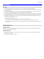
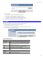
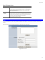
Load/Backup Screen
Use the Load/Backup link on the Setup menu. An example screen is shown below.
Figure 10: Load/Back Screen
Data - Load/Backup Screen
Administration
WAN
There are 3 modes:
1. If Enable is selected for WAN 1, then choose Backup for WAN 2.
2. If Load Balance is selected for WAN 1, then choose Load Balance for WAN 2.
3. If Backup is selected for WAN 1, then choose Enable for WAN 2.
Auto
Equilibrium Type has 2 options:
Exceptions
•
Determine by Bandwidth: If selected, enter the desired values of
WAN1 and WAN2 Bandwidth.
•
Connection balanced automatically: Enter the percentage in the
Primary Port Proportion field.
Set up "Local IP Range", "Remote IP Range" or "Remote Port" to
direct the connection through secondary port.
18
Setup
19
Chapter 4
PC Configuration
4
This Chapter details the PC Configuration required on the local ("Internal") LAN.
Overview
For each PC, the following may need to be configured:
•
TCP/IP network settings
•
Internet Access configuration
Windows Clients
This section describes how to configure Windows clients for Internet access via the Broadband VPN Gateway.
The first step is to check the PC's TCP/IP settings.
The Broadband VPN Gateway uses the TCP/IP network protocol for all functions, so it is essential that the TCP/IP protocol be installed and configured on each PC.
TCP/IP Settings - Overview
If using the default Broadband VPN Gateway settings, and the default Windows TCP/IP settings, no
changes need to be made.
•
By default, the Broadband VPN Gateway will act as a DHCP Server, automatically providing a suitable IP Address (and related
information) to each PC when the PC boots.
•
For all non-Server versions of Windows, the default TCP/IP setting is to act as a DHCP client.
If using a Fixed (specified) IP address, the following changes are required:
•
The Gateway must be set to the IP address of the Broadband VPN Gateway
•
The DNS should be set to the address provided by your ISP.
If your LAN has a Router, the LAN Administrator must reconfigure the Router itself. Refer to Chapter 8 - Other
Features and Operations for details.
20
PC Configuration
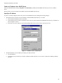
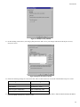
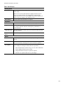
Checking TCP/IP Settings - Windows 9x/ME:
1.
Select Control Panel - Network. You should see a screen like the following:
Figure 11: Network Configuration
2.
3.
Select the TCP/IP protocol for your network card.
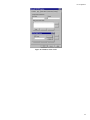
Click on the Properties button. You should then see a screen like the following.
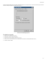
Figure 12: IP Address (Win 95)
Ensure your TCP/IP settings are correct, as follows:
Using DHCP
To use DHCP, select the radio button Obtain an IP Address automatically. This is the default Windows setting. Using this is recommended. By default, the Broadband VPN Gateway will act as a DHCP Server.
Restart your PC to ensure it obtains an IP Address from the Broadband VPN Gateway.
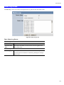
Using "Specify an IP Address"
If your PC is already configured, check with your network administrator before making the following changes:
•
On the Gateway tab, enter the Broadband VPN Gateway 's IP address in the New Gateway field and click Add, as shown below.
Your LAN administrator can advise you of the IP Address they assigned to the Broadband VPN Gateway.
21
Broadband VPN Gateway User Guide
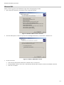
Figure 13: Gateway Tab (Win 95/98)
•
On the DNS Configuration tab, ensure Enable DNS is selected. If the DNS Server Search Order list is empty, enter the DNS
address provided by your ISP in the fields beside the Add button, then click Add.
Figure 14: DNS Tab (Win 95/98)
22
PC Configuration
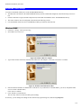
Checking TCP/IP Settings - Windows NT4.0
1.
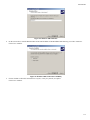
Select Control Panel - Network, and, on the Protocols tab, select the TCP/IP protocol, as shown below.
Figure 15: Windows NT4.0 - TCP/IP
2.
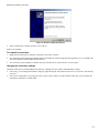
Click the Properties button to see a screen like the one below.
Figure 16: Windows NT4.0 - IP Address
3.
4.
Select the network card for your LAN.
Select the appropriate radio button - Obtain an IP address from a DHCP Server or Specify an IP Address, as explained below.
23
Broadband VPN Gateway User Guide
Obtain an IP address from a DHCP Server
This is the default Windows setting. Using this is recommended. By default, the Broadband VPN Gateway will act as a DHCP
Server.
Restart your PC to ensure it obtains an IP Address from the Broadband VPN Gateway.
Specify an IP Address
If your PC is already configured, check with your network administrator before making the following changes.
1.
The Default Gateway must be set to the IP address of the Broadband VPN Gateway. To set this:
•
Click the Advanced button on the screen above.
•
On the following screen, click the Add button in the Gateways panel, and enter the Broadband VPN Gateway 's IP address, as
shown in Figure 17 below.
•
If necessary, use the Up button to make the Broadband VPN Gateway the first entry in the Gateways list.
Figure 17 - Windows NT4.0 - Add Gateway
2.
The DNS should be set to the address provided by your ISP, as follows:
•
Click the DNS tab.
•
On the DNS screen, shown below, click the Add button (under DNS Service Search Order), and enter the DNS provided by
your ISP.
24
PC Configuration
Figure 18: Windows NT4.0 - DNS
25
Broadband VPN Gateway User Guide
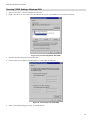
Checking TCP/IP Settings - Windows 2000:
1.
2.
Select Control Panel - Network and Dial-up Connection.
Right - click the Local Area Connection icon and select Properties. You should see a screen like the following:
Figure 19: Network Configuration (Win 2000)
3.
4.
Select the TCP/IP protocol for your network card.
Click on the Properties button. You should then see a screen like the following.
Figure 20: TCP/IP Properties (Win 2000)
5.
Ensure your TCP/IP settings are correct, as described below.
26
PC Configuration
Using DHCP
To use DHCP, select the radio button Obtain an IP Address automatically. This is the default Windows setting. Using this is recommended. By default, the Broadband VPN Gateway will act as a DHCP Server.
Restart your PC to ensure it obtains an IP Address from the Broadband VPN Gateway.
Using a fixed IP Address ("Use the following IP Address")
If your PC is already configured, check with your network administrator before making the following changes.
•
Enter the Broadband VPN Gateway 's IP address in the Default gateway field and click OK. (Your LAN administrator can advise
you of the IP Address they assigned to the Broadband VPN Gateway.)
•
If the DNS Server fields are empty, select Use the following DNS server addresses, and enter the DNS address or addresses
provided by your ISP, then click OK.
27
Broadband VPN Gateway User Guide
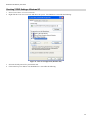
Checking TCP/IP Settings - Windows XP
1.
2.
Select Control Panel - Network Connection.
Right click the Local Area Connection and choose Properties. You should see a screen like the following:
Figure 21: Network Configuration (Windows XP)
3.
4.
Select the TCP/IP protocol for your network card.
Click on the Properties button. You should then see a screen like the following.
28
PC Configuration
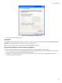
Figure 22: TCP/IP Properties (Windows XP)
5.
Ensure your TCP/IP settings are correct.
Using DHCP
To use DHCP, select the radio button Obtain an IP Address automatically. This is the default Windows setting. Using this is recommended. By default, the Broadband VPN Gateway will act as a DHCP Server.
Restart your PC to ensure it obtains an IP Address from the Broadband VPN Gateway.
Using a fixed IP Address ("Use the following IP Address")
If your PC is already configured, check with your network administrator before making the following changes.
•
In the Default gateway field, enter the Broadband VPN Gateway 's IP address and click OK. Your LAN administrator can advise
you of the IP Address they assigned to the Broadband VPN Gateway.
•
If the DNS Server fields are empty, select Use the following DNS server addresses, and enter the DNS address or addresses
provided by your ISP, then click OK.
29
Broadband VPN Gateway User Guide
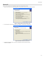
Checking TCP/IP Settings - Windows Vista
1.
From the Start menu, right-click Network, then click Properties. Now, the Network and Sharing Center displays.
2.
Under Tasks located on the left-hand side of the window, click Manage network connections.
3.
In Network Connections window displays, right click on the correct Local Area Connection, then click Properties.
4.
Pop-up window displays that states Windows needs your permission to continue. Click Continue to open the Local Area Connection Properties window
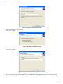
5.
Select Internet Protocol Version 4 (TCP/IPv4), then click Properties. From the General tab, verify that Obtain an IP address
automatically and Obtain DNS server address automatically are selected. Click the OK button.
30
PC Configuration
31
Broadband VPN Gateway User Guide
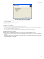
Internet Access
To configure your PCs to use the Broadband VPN Gateway for Internet access:
•
Ensure that the DSL modem, Cable modem, or other permanent connection is functional.
•
Use the following procedure to configure your Browser to access the Internet via the LAN, rather than by a Dial-up connection.
For Windows 9x/ME/2000
1.
2.
3.
4.
5.
6.
7.
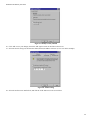
Select Start Menu - Settings - Control Panel - Internet Options.
Select the Connection tab, and click the Setup button.
Select "I want to set up my Internet connection manually, or I want to connect through a local area network (LAN)" and click
Next.
Select "I connect through a local area network (LAN)" and click Next.
Ensure all of the boxes on the following Local area network Internet Configuration screen are unchecked.
Check the "No" option when prompted "Do you want to set up an Internet mail account now?".
Click Finish to close the Internet Connection Wizard.
Setup is now completed.
For Windows XP
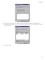
1.
2.
3.
4.
5.
6.
7.
8.
9.
Select Start Menu - Control Panel - Network and Internet Connections.
Select Set up or change your Internet Connection.
Select the Connection tab, and click the Setup button.
Cancel the pop-up "Location Information" screen.
Click Next on the "New Connection Wizard" screen.
Select "Connect to the Internet" and click Next.
Select "Set up my connection manually" and click Next.
Check "Connect using a broadband connection that is always on" and click Next.
Click Finish to close the New Connection Wizard.
Setup is now completed.
Accessing AOL
To access AOL (America On Line) through the Broadband VPN Gateway, the AOL for Windows software must be configured to use
TCP/IP network access, rather than a dial-up connection. The configuration process is as follows:
•
Start the AOL for Windows communication software. Ensure that it is Version 2.5, 3.0 or later. This procedure will not work with
earlier versions.
•
Click the Setup button.
•
Select Create Location, and change the location name from "New Locality" to "Broadband VPN Gateway ".
•
Click Edit Location. Select TCP/IP for the Network field. (Leave the Phone Number blank.)
•
Click Save, then OK.
Configuration is now complete.
•
Before clicking "Sign On", always ensure that you are using the "Broadband VPN Gateway " location.
32
PC Configuration
Macintosh Clients
From your Macintosh, you can access the Internet via the Broadband VPN Gateway. The procedure is as follows.
1. Open the TCP/IP Control Panel.
2. Select Ethernet from the Connect via pop-up menu.
3. Select Using DHCP Server from the Configure pop-up menu. The DHCP Client ID field can be left blank.
4. Close the TCP/IP panel, saving your settings.
Note:
If using manually assigned IP addresses instead of DHCP, the required changes are:
•
Set the Router Address field to the Broadband VPN Gateway 's IP Address.
•
Ensure your DNS settings are correct.
Linux Clients
To access the Internet via the Broadband VPN Gateway, it is only necessary to set the Broadband VPN Gateway as the "Gateway".
Ensure you are logged in as "root" before attempting any changes.
Fixed IP Address
By default, most Unix installations use a fixed IP Address. If you wish to continue using a fixed IP Address, make the following
changes to your configuration.
•
Set your "Default Gateway" to the IP Address of the Broadband VPN Gateway.
•
Ensure your DNS (Name server) settings are correct.
To act as a DHCP Client (recommended)
The procedure below may vary according to your version of Linux and X -windows shell.
1. Start your X Windows client.
2. Select Control Panel - Network
3. Select the "Interface" entry for your Network card. Normally, this will be called "eth0".
4. Click the Edit button, set the "protocol" to "DHCP", and save this data.
5. To apply your changes
•
Use the "Deactivate" and "Activate" buttons, if available.
•
OR, restart your system.
Other Unix Systems
To access the Internet via the Broadband VPN Gateway:
• Ensure the "Gateway" field for your network card is set to the IP Address of the Broadband VPN Gateway.
•
Ensure your DNS (Name Server) settings are correct.
33
Chapter 5
Operation and Status
5
This Chapter details the operation of the Broadband VPN Gateway and the status screens.
Operation
Once both the Broadband VPN Gateway and the PCs are configured, operation is automatic.
However, there are some situations where additional Internet configuration may be required:
•
If using Internet-based Communication Applications, it may be necessary to specify which PC receives an incoming connection.
Refer to Chapter 6 - Internet Features for further details.
•
Applications which use non-standard connections or port numbers may be blocked by the Broadband VPN Gateway 's built-in
firewall. You can define such applications as Special Applications to allow them to function normally. Refer to Chapter 6 - Internet Features for further details.
•
Some non-standard applications may require use of the DMZ feature. Refer to Chapter 6 - Internet Features for further details.
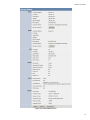
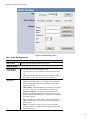
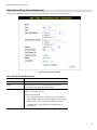
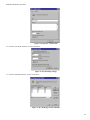
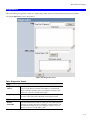
Status Screen
Use the Status link on the main menu to view this screen.
34
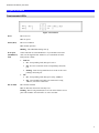
Operation and Status
Figure 23: General Status Screen
35
Broadband VPN Gateway User Guide
Data - General Status Screen
WAN1/2
Connection Method
This indicates the current connection method.
IP Address
This IP Address is allocated by the ISP (Internet Service Provider).
Subnet Mask
The Subnet Mask associated with the IP Address above.
Gateway
The IP Address of the remote Gateway or Router associated with
the IP Address above.
DNS IP Address
The IP Address of the Domain Name Server which is currently
used.
MAC Address
Also called Network Adapter Address or Physical Address. This
is a low-level identifier, as seen from the WAN port.
Connection Status
It displays the current connection status.
Internet Connection
Click the button to connect or disconnect the internet connection.
LAN
Port Status
This shows the status of the port.
IP Address
The IP Address of the Broadband VPN Gateway.
Subnet Mask
The Subnet Mask for the IP Address above.
MAC Address
Also called Network Adapter Address or Physical Address.
DHCP Server
This shows the status of the DHCP Server function.
For additional information about the PCs on your LAN, and the
IP addresses allocated to them, use the PC Database option on
the Advanced menu.
DHCP Clients
This shows the number of DHCP clients supported.
Firewall
Firewall
This shows the current settings of the firewall.
Kernel
Kernel
This shows the current status of the kernel.
System
Device Name
This displays the current name of the Broadband VPN Gateway.
Firmware Version
The current version of the firmware installed in the Broadband
VPN Gateway.
System Up/Run Time
This shows the system running time.
Session Loading
This indicates the loading status of the session.
Language Version
This shows the language version of the Broadband VPN Gateway.
Buttons
Restart
Restart (reboot) the Router. You will have to wait for the restart
to be completed before continuing.
Refresh Screen
Update the data displayed on screen.
36
Operation and Status
Show Status
Display the usage of the CPU and Memory in a sub-window.
Port Status
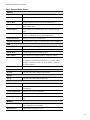
Click the "Port Status" button on the Status Log menu. An example screen is shown below.
Figure 24: Port Status Screen
Data - Port Status Screen
Port Status
Network Flow
The picture shows the current network flow.
Buttons
Refresh
Update the data on screen.
Send Network Log
Click this button will send the log to the specified E-mail address.
37
Broadband VPN Gateway User Guide
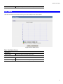
Event Log
An example screen is shown below.
Figure 25: Event Log Screen
Data - Event Log Screen
Event Log
Time
It displays the time when the event occurred.
Event
It describes the details of the event.
Host
It displays the IP Address of the server.
Buttons
Refresh
Update the data shown on screen.
Clear
Delete all data currently in the Log.
38
Operation and Status
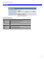
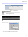
URL Log
An example screen is shown below.
Figure 26: URL Log
Data - URL Log
Internet
Time
It displays the time when the log occurred.
Event
It describes the address of the URL.
PC
It displays the IP Address of the PC.
Buttons
Refresh
Update the data shown on screen.
Clear
Delete all data currently in the Log.
39
Broadband VPN Gateway User Guide
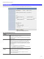
System Log
An example screen is shown below.
Figure 27: System Log
Data - System Log Screen
System Log
Search Type
Select the desired options of search type. Click the “Search” button
to see the logs in the following log table.
Time
It displays the time when the system log occurred.
Event
It describes the details of the event.
Data Packet
Description
It displays the type, source and destination address of the packet.
40
Chapter 6
Internet Features
6
This Chapter explains when and how to use the Broadband VPN Gateway's "Internet" Features.
Overview
The following advanced features are provided.
•
Address List
•
PC Database
•
URL Filter
•
Dynamic DNS
•
Static Routing
•
QoS
41
Broadband VPN Gateway User Guide
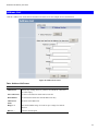
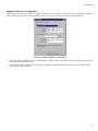
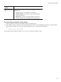
Address List
Click the "Address List" on the Advanced menu to access the screen. An example screen is shown below.
Figure 28: Address List Screen
Data - Address List Screen
Address List
Address List
This lists any existing entries. If you have not entered any values, this
list will be empty.
Select All/Cancel
Use this to select/deselect all the entries in the list.
Delete Button
Use this button to delete the selected address list entry
Address List
Name
The name of the address list.
Range 1~4
Enter the IP Address range. You can set up to 4 ranges for each address list.
Rule for …
Select the desired option.
42
Internet Features
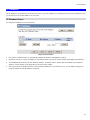
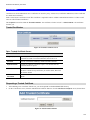
PC Database
The PC Database is used whenever you need to select a PC (e.g. for the "DMZ" PC). It eliminates the need to enter IP addresses. Also,
you do not need to use fixed IP addresses on your LAN.
PC Database Screen
An example PC Database screen is shown below.
Figure 29: PC Database
•
PCs which are "DHCP Clients" are automatically added to the database, and updated as required.
•
By default, non-Server versions of Windows act as "DHCP Clients"; this setting is called "Obtain an IP Address automatically".
•
The Broadband VPN Gateway uses the "Hardware Address" to identify each PC, not the name or IP address. The "Hardware
Address" can only change if you change the PC's network card or adapter.
•
This system means you do NOT need to use Fixed (static) IP addresses on your LAN. However, you can add PCs using Fixed
(static) IP Addresses to the PC database if required.
43
Broadband VPN Gateway User Guide
Data - PC Database Screen
PC List
This lists all current entries. Data displayed is PC Name, MAC Address, IP Address and Certify.
Buttons
Edit
To Edit or modify an existing entry, select it and click the "Edit"
button.
Delete
Delete the selected PC from the list. This should be done in 2 situations:
•
The PC has been removed from your LAN.
•
The entry is incorrect.
Add
This will add the new PC to the list. The PC will be sent a "ping" to
determine its hardware address. If the PC is not available (not connected, or not powered On) you will not be able to add it.
Refresh
Update the data on screen.
44
Internet Features
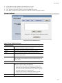
URL Filter
The URL Filter allows you to block access to undesirable Web site.
An example screen is shown below.
Figure 30: URL Filter Screen
Data - URL Filter Screen
Filter Strings
Current Entries
This lists any existing entries. If you have not entered any values, this
list will be empty.
URL Filter Rule
List
Select the desired rule from the list.
URL Filter Rule
Name
After the URL Filter Rule is selected, enter the desired name in this
field. Click Edit button to modify the setting
45
Broadband VPN Gateway User Guide
Add Key Words
To add an entry to the list, enter it here, and click the "Add" button.
An entry may be a Domain name (e.g. www.trash.com) or simply a
string. (e.g. ads/ )
Any URL which contains ANY entry ANYWHERE in the URL will
be blocked.
Buttons
Delete Selected/Delete All
Use these buttons to delete the selected entry or all entries, as required.
Multiple entries can be selected by holding down the CTRL key while
selecting. (On the Macintosh, hold the SHIFT key while selecting.)
Add
Use this to add the current Filter String to the site list.
Modify Rule
Click the "Modify Rule" button to edit an existing rule.
46
Internet Features
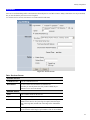
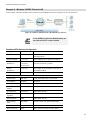
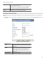
Dynamic DNS
This free service is very useful when combined with the Virtual Server feature. It allows Internet users to connect to your Virtual
Servers using a URL, rather than an IP Address.
This also solves the problem of having a dynamic IP address. With a dynamic IP address, your IP address may change whenever you
connect, which makes it difficult to connect to you.
The Service works as follows:
1. You must register for the service at one of the listed DDNS Service providers.
2. After registration, follow the Service Provider's procedure to request a Domain Name, and have it allocated to you.
3. Enter your DDNS data on the Broadband VPN Gateway's DDNS screen (shown below).
4. The Broadband VPN Gateway will then automatically ensure that your current IP Address is recorded and updated at the DDNS
server.
If the DDNS Service provides software to perform this "IP address update"; you should disable the "Update" function, or not use
the software at all.
5. From the Internet, users will be able to connect to your Virtual Servers (or DMZ PC) using your Domain name, as shown on this
screen.
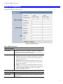
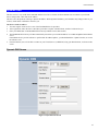
Dynamic DNS Screen
Figure 31: Dynamic DNS Screen
47
Broadband VPN Gateway User Guide
Data - Dynamic DNS Screen
WAN1/2
DDNS Service
Select the desired DDNS Service provider.
Web Site Button
Click this button to open a new window and connect to the Web site
for the selected DDNS service provider.
DDNS Status
•
This message is returned by the DDNS Server
•
Normally, this message should be something like "Update
successful" or "IP address updated".
•
If the message indicates some problem, you need to connect to
the DDNS Service provider and correct this problem.
User Name
Enter your Username for the DDNS Service.
Password
Enter your current password for the DDNS Service.
Domain Name
Enter the domain name allocated to you by the DDNS Service. If you
have more than one name, enter the name you wish to use.
48
Internet Features
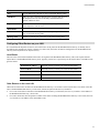
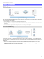
Static Routing
Overview
•
If you don't have other Routers or Gateways on your LAN, you can ignore the "Routing" page completely.
•
If the Broadband VPN Gateway is only acting as a Gateway for the local LAN segment, ignore the "Routing" page even if your
LAN has other Routers.
•
If your LAN has a standard Router (e.g. Cisco) on your LAN, and the Broadband VPN Gateway is to act as a Gateway for all
LAN segments, enable RIP (Routing Information Protocol) and ignore the Static Routing table.
•
If your LAN has other Gateways and Routers, and you wish to control which LAN segments use each Gateway, do NOT enable
RIP (Routing Information Protocol). Configure the Static Routing table instead. (You also need to configure the other Routers.)
•
If using Windows 2000 Data center Server as a software Router, enable RIP on the Broadband VPN Gateway, and ensure the
following Windows 2000 settings are correct:
•
Open Routing and Remote Access
•
In the console tree, select Routing and Remote Access, [server name], IP Routing, RIP
•
In the "Details" pane, right-click the interface you want to configure for RIP version 2, and then click "Properties".
•
On the "General" tab, set Outgoing packet protocol to "RIP version 2 broadcast", and Incoming packet protocol to "RIP version 1 and 2".
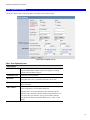
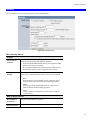
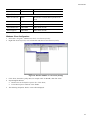
Static Routing Screen
Using this Screen
Generally, you will use either RIP (Routing Information Protocol) OR the Static Routing Table, as explained above, although is it
possible to use both methods simultaneously.
Static Routing Table
•
If RIP is not used, an entry in the routing table is required for each LAN segment on your Network, other than the segment to
which this device is attached.
•
The other Routers must also be configured.
49
Broadband VPN Gateway User Guide
Figure 32: Static Routing Screen
Data - Static Routing Screen
RIP
RIP Version
Select the desired option from the drop-down list.
Static Routing
Static Routing
Table Entries
Properties
This list shows all entries in the Routing Table.
•
The "Properties" area shows details of the selected item in the
list.
•
Change any the properties as required, then click the "Update
Route" button to save the changes to the selected entry.
•
Destination Network - The network address of the remote LAN
segment. For standard class "C" LANs, the network address is
the first 3 fields of the Destination IP Address. The 4th (last)
field can be left at 0.
•
Subnet Mask - The Subnet Mask for the remote LAN segment.
For class "C" networks, the default mask is 255.255.255.0
•
Gateway IP Address - The IP Address of the Gateway or
Router which the Broadband VPN Gateway must use to communicate with the destination above. (NOT the router attached to
the remote segment.)
•
Port - Normally, this will be "LAN". If NAT is disabled, the
"WAN" option can be used for Routers which are accessed via
the WAN port.
•
Metric - The number of "hops" (routers) to pass through to
reach the remote LAN segment. The shortest path will be used.
The default value is 1.
50
Internet Features
Buttons
Save
Save the RIP setting. This has no effect on the Static Routing Table.
Add Route
Add a new entry to the Static Routing table, using the data shown in
the "Properties" area on screen. The entry selected in the list is
ignored, and has no effect.
Update Route
Update the current Static Routing Table entry, using the data shown
in the "Properties" area on screen.
Delete Route
Delete the current Static Routing Table entry.
Clear
Clear all data from the "Properties" area, ready for input of a new
entry for the Static Routing table.
Routing Table
Generate a read-only list of all entries in the Static Routing table.
Configuring Other Routers on your LAN
It is essential that all IP packets for devices not on the local LAN be passed to the Broadband VPN Gateway, so that they can be
forwarded to the external LAN, WAN, or Internet. To achieve this, the local LAN must be configured to use the Broadband VPN
Gateway as the Default Route or Default Gateway.
Local Router
The local router is the Router installed on the same LAN segment as the Broadband VPN Gateway. This router requires that the
Default Route is the Broadband VPN Gateway itself. Typically, routers have a special entry for the Default Route. It should be configured as follows.
Destination IP Address
Normally 0.0.0.0, but check your router documentation.
Network Mask
Normally 0.0.0.0, but check your router documentation.
Gateway IP Address
The IP Address of the Broadband VPN Gateway.
Interface
LAN
Metric
2
Other Routers on the Local LAN
Other routers on the local LAN must use the Broadband VPN Gateway 's Local Router as the Default Route. The entries will be the
same as the Broadband VPN Gateway 's local router, with the exception of the Gateway IP Address.
•
For a router with a direct connection to the Broadband VPN Gateway 's local Router, the Gateway IP Address is the address of
the Broadband VPN Gateway 's local router.
•
For routers which must forward packets to another router before reaching the Broadband VPN Gateway 's local router, the Gateway IP Address is the address of the intermediate router.
51
Broadband VPN Gateway User Guide
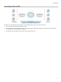
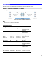
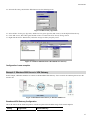
Static Routing - Example
Figure 33: Routing Example
For the Broadband VPN Gateway 's Routing Table
For the LAN shown above, with 2 routers and 3 LAN segments, the Broadband VPN Gateway requires 2 entries as follows.
Entry 1 (Segment 1)
Destination IP Address
192.168.1.0
Network Mask
255.255.255.0 (Standard Class C)
Gateway IP Address
192.168.0.100 (Broadband VPN Gateway 's
local Router)
Interface
LAN
Metric
2
Entry 2 (Segment 2)
Destination IP Address
192.168.2.0
Network Mask
255.255.255.0 (Standard Class C)
Gateway IP Address
192.168.0.100
Interface
LAN
Metric
3
For Router A's Default Route
Destination IP Address
0.0.0.0
Network Mask
0.0.0.0
Gateway IP Address
192.168.0.1 (Broadband VPN Gateway 's IP
Address)
Interface
LAN
For Router B's Default Route
Destination IP Address
0.0.0.0
52
Internet Features
Network Mask
0.0.0.0
Gateway IP Address
192.168.1.80 (Broadband VPN Gateway 's
local router)
Interface
LAN
53
Broadband VPN Gateway User Guide
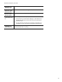
QoS
Quality of Service (QoS) ensures better service to high-priority service.
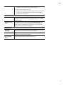
Figure 34: QoS Screen
Data - QoS Screen
QoS Setting
QoS Method
Select the desired option.
•
Disabled
•
Based on data packet type
54
Internet Features
•
•
QoS Queue: It displays the queue type.
•
Priority: Enter the priority value (1~20) of the policy.
•
Reliability: Select the desired option from the drop-down
list.
•
Speed Limit: Enter the desired values for the inbound and
outbound traffic limitation.
Based on QoS rules set below
•
Policy Name: It displays the name for the policy.
•
Throughput: It displays the information of the traffic.
•
Queue: Select the desired option.
•
Enable: Check this to enable this policy.
•
Qos Traffic Button: Click this button to access the subscreen, and define the traffic for the selected policy.
55
Chapter 7
Security Configuration
7
This Chapter explains the settings available via the security configuration section of the "Security" menu.
Overview
The following advanced configurations are provided.
•
Rules
•
Schedules
•
Log Setting
•
Services
•
Security
•
DMZ
•
E-Mail
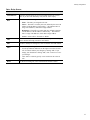
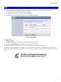
Rules
For normal operation and LAN protection, it is not necessary to use this screen.
The Firewall will always block DoS (Denial of Service) attacks. A DoS attack does not attempt to steal data or damage your PCs, but
overloads your Internet connection so you can not use it - the service is unavailable.
As well, you can use this screen to create Firewall rules to block or allow specific traffic. But incorrect configuration may cause
serious problems.
This feature is for advanced administrators only!
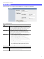
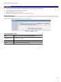
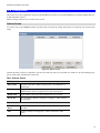
Rules Screen
Click the Rules option on the Firewall menu to see a screen like the following example. This example contains two (2) rules for
outgoing traffic.
Figure 35: Rules Screen
56
Security Configuration
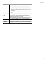
Data - Rules Screen
Outbound/Inbound Connection
View Rules for..
Select the desired option; the screen will update and list any current
rules. If you have not defined any rules, the list will be empty.
Data
For each rule, the following data is shown:
•
Name - The name you assigned to the rule.
•
Source - The traffic covered by this rule, defined by the source IP
address. If the IP address is followed by ... this indicates there is
range of IP addresses, rather than a single address.
•
Destination - The traffic covered by this rule, defined by destination IP address. If the IP address is followed by ... this indicates
there is range of IP addresses, rather than a single address.
•
Action - Action will be "Forward" or "Block"
Add
To add a new rule, click the "Add" button, and complete the resulting
screen. See the following section for more details.
Edit
To Edit or modify an existing rule, select it and click the "Edit" button.
Move
There are 2 ways to change the order of rules
Delete
•
Use the up and down indicators on the right to move the selected
rule. You must confirm your changes by clicking "OK". If you
change your mind before clicking "OK", click "Cancel" to reverse
your changes.
•
Click "Move" to directly specify a new location for the selected
rule.
To delete an existing rule, select it and click the "Delete" button.
57
Broadband VPN Gateway User Guide
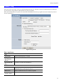
Define Firewall Rule (Inbound/Outbound)
Clicking the "Add" button in the Firewall Rules screen will display a screen like the example below.
Figure 36: Define Firewall Rule
Data - Define Firewall Rule Screen
Name
Enter a suitable name for this rule.
Port
Select the desired port as required.
Type
This determines the source and destination ports for traffic
covered by this rule. Select the desired option.
Source IP
These settings determine which traffic, based on their source IP
address, is covered by this rule.
Select the desired option:
•
Any - All traffic from the source port is covered by this rule.
•
Single address - Enter the required IP address in the "Start IP
address" field". You can ignore the "Subnet Mask" field.
•
IP Address List - If this option is selected, choose the required option.
58
Security Configuration
Dest IP
These settings determine which traffic, based on their destination
IP address, is covered by this rule.
Select the desired option:
•
Any - All traffic from the source port is covered by this rule.
•
Single address - Enter the required IP address in the "Start IP
address" field". You can ignore the "Subnet Mask" field.
•
IP Address List - If this option is selected, choose the required option.
Services
Select the desired Service or Services. This determines which
packets are covered by this rule, based on the protocol (TPC or
UDP) and port number. If necessary, you can define a new
Service on the "Services" screen, by defining the protocols and
port numbers used by the Service.
Advanced Rule
Select the desired advanced rule .
Port Transfer To
Enter the required data.
Select Schedule
Select the desired option from the list.
Action
Select the desired action for packets covered by this rule:
Log Setting
This determines whether packets covered by this rule are logged.
Select the desired option.
59
Broadband VPN Gateway User Guide
Schedules
•
Blocking will be performed during the scheduled time (between the "Begin" and "End" times.)
•
Two (2) separate sessions or periods can be defined.
•
Times must be entered using a 24 hr clock.
•
If the time for a particular day is blank, no action will be performed.
Schedules Screen
This screen is accessed by the Schedules link on the Firewall menu.
Figure 37: Schedules Screen
Data - Schedules Screen
Day
Each day of the week can be scheduled independently.
Time Interval 1
Time Interval 2
Two (2) separate sessions or periods can be defined. Session 2 can be
left blank if not required.
Begin
Enter the start using a 24 hr clock.
End
Enter the finish time using a 24 hr clock.
60
Security Configuration
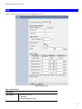
Firewall -- Log
The Logs record various types of activity on the Broadband VPN Gateway. This data is useful for troubleshooting, but enabling all
logs will generate a large amount of data and adversely affect performance.
Since only a limited amount of log data can be stored in the Broadband VPN Gateway, log data can also be E-mailed to your PC or
sent to a Syslog Server.
Figure 38: Log Screen
Data - Log Screen
Log
Log Contents
Select the desired option(s), if needed.
Throughput/Connection
Interval
Enter the desired time for the interval.
Delete Redundant
Log
If enabled, it will delete the redundant log.
Time Zone
Time Zone
Select the correct Time Zone for your location. This is required for
the date/time shown on the logs to be correct.
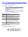
Time Server…
Enable or disable the Time Server feature as required.
First Server
Name/IP Address
Enter the address or name for the desired Time Server.
61
Broadband VPN Gateway User Guide
Second Server
Name/IP Address
This is optional.
System Log
Enable System Log
If enabled, log data will be sent to your system log Server.
System Log Server
Enter the IP address of your System Log Server.
Include
Select the logs you wish to be included in the data sent to the
System Log Server.
62
Security Configuration
Services
Services are used in defining traffic to be blocked or allowed by the Firewall Rules features. Many common Services are pre-defined,
but you can also define your own services if required.
To view the Services screen, select the Services link on the Firewall menu.
Figure 39: Services Screen
Data - Services Screen
Available Services
Available Services
This lists all defined Services.
Delete Button
Use this to delete the selected Service from the list.
Note that you can only delete Services you have added; the predefined services can not be deleted.
Add New Service
Name
Enter a suitable name for this Service.
Type
Select the correct type for this Service.
Start Port
If the "Type" (above) is TCP, UDP, or TCP/UDP, enter the port
number for this Service. If a port range is required, enter the beginning of the range here, and the end of the range in the "Finish Port"
field.
End Port
If the "Type" (above) is TCP, UDP, or TCP/UDP, this field can be
used to enter the end of range of port numbers. This can be left blank
63
Broadband VPN Gateway User Guide
if not required.
64
Security Configuration
Security
This screen allows you to set Firewall and other security-related options.
Figure 40: Security Screen
Data - Security Screen
Firewall
Echo ICMP on
LAN Port
Allow VPN passthrough
The ICMP protocol is used by the "ping" and "trace route" programs,
and by network monitoring and diagnostic programs.
•
If checked, the Broadband VPN Gateway will respond to ICMP
packets received from the Internet.
•
If not checked, ICMP packets from the Internet will be ignored.
Disabling this option provides a slight increase in security.
If enabled, PCs on the LAN can use VPN software to connect to
remote clients via the Internet connection. The protocols supported
are:
•
IPSec
IPSec protocol is used to establish a secure connection, and is
widely used by VPN (Virtual Private Networking) programs.
•
PPTP
PPTP (Point to Point Tunneling Protocol) is widely used by
VPN (Virtual Private Networking) programs.
•
L2TP
L2TP is a protocol developed by Cisco for VPNs (Virtual Private Networks).
MAX 3D Engine Options
Host number in
the network
Select the desired number as required.
Network used in
Select the desired internet environment as required.
65
Broadband VPN Gateway User Guide
Maximum Connections per PC
Enter the maximum value for the connections of each PC.
Maximum Applications per host
Enter the maximum value for the applications of each host.
Set New Connection(s) not upto:
Set the value to control the speed of the internet.
Connection Priority
There are 2 options to set the priority:
TCP/UDP Connection time out
•
Connection may be released after idling for - The connection is
automatically disconnected when idle for the time period specified in this field.
•
Use QoS when the network load is reaching its maximum level If enabled, the router will check all connections in the network.
It is recommended not to change the default value. It will be used
when the network flow is very big.
66
Security Configuration
DMZ
This feature, if enabled, allows the DMZ computer or computers on your LAN to be exposed to all users on the Internet.
•
This allows almost any application to be used on the "DMZ PC".
•
The "DMZ PC" will receive all "Unknown" connections and data.
•
If the DMZ feature is enabled, you must select the PC to be used as the "DMZ PC".
Figure 41: Multi-DMZ
To use this feature:
•
Enable this DMZ.
•
The WAN IP address field displays the IP address allocated to you by your ISP.
•
Enter the Corresponding IP to be the DMZ PC for traffic sent to this IP address.
If you have multiple Internet IP addresses, you can assign one DMZ PC for each Internet IP address.
If you only have 1 WAN IP address, only "DMZ 1" can be used, and only one (1) PC can be the DMZ PC. The current WAN IP
address is displayed. If this address is assigned upon connection, and no connection currently exists, then this address will be blank or
0.0.0.0.
The "DMZ PC" is effectively outside the Firewall, making it more vulnerable to attacks. For this reason, you
should only enable the DMZ feature when required.
67
Broadband VPN Gateway User Guide
E-Mail
Figure 42: E-Mail Screen
Data - E-Mail Screen
E-Mail Alert
Send E-Mail alert
If enabled, an E-Mail will be sent immediately if a DoS (Denial
of Service) attack is detected. If enabled, the E-mail address
information must be provided.
Send E-Mail alert…
If enabled, an E-Mail will be sent immediately if an application
reaches 90% of its limited capacity.
Send E-Mail alert…
If enabled, an E-Mail will be sent immediately if the PC’s connection reaches 90% of its limitation.
E-Mail Log
Use E-Mail to send
log
If enabled, logs will be logs to the specified E-mail address. You
need to select the Logs to be E-mailed, and complete the E-mail
address settings on this screen.
Include
Select the log items to be included in the E-mail.
68
Security Configuration
Send
Select the desired option for sending the log by E-mail.
•
When the log is full - The time is not fixed. The log will be
sent when the log is full, which will depend on the volume of
traffic.
•
Every day, Every Monday... - The log is sent on the interval specified.
•
If "Every day" is selected, the log is sent at the time specified.
•
If the day is specified, the log is sent once per week, on
the specified day.
•
Select the time of day you wish the E-mail to be sent.
•
If the log is full before the time specified to send it, it
will be sent regardless.
E-mail Address
Enter the E-mail address the Log is to be sent to. The E-mail will
also show this address as the Sender's address.
Subject
Enter the text string to be shown in the "Subject" field for the Email.
SMTP Server
Enter the domain name or IP address of the SMTP (Simple Mail
Transport Protocol) Server you use for outgoing E-mail.
User Name
Enter the user name for the E-mail account.
Password
Enter the password for the E-mail account.
Port Number
Enter the port number used to connect to the SMTP Server. The
default value is 25.
E-Mail Test Button
Click this button to send a test E-Mail to the above E-Mail address.
69
Chapter 8
VPN (IPSec)
8
This Chapter describes the VPN capabilities and configuration required for common situations.
Overview
This section describes the VPN (Virtual Private Network) support provided by your Broadband VPN Gateway.
A VPN (Virtual Private Network) provides a secure connection between 2 points, over an insecure network - typically the Internet.
This secure connection is called a VPN Tunnel.
There are many standards and protocols for VPNs. The standard implemented in the Broadband VPN Gateway is IPSec.
IPSec
IPSec is a near-ubiquitous VPN security standard, designed for use with TCP/IP networks. It works at the packet level, and authenticates and encrypts all packets traveling over the VPN Tunnel. Thus, it does not matter what applications are used on your PC. Any
application can use the VPN like any other network connection.
IPsec VPNs exchange information through logical connections called SAs (Security Associations). An SA is simply a definition of the
protocols, algorithms and keys used between the two VPN devices (endpoints).
Each IPsec VPN has two SAs - one in each direction. If IKE (Internet Key Exchange) is used to generate and exchange keys, there
are also SA's for the IKE connection as well as the IPsec connection.
There are two security modes possible with IPSec:
•
Transport Mode - the payload (data) part of the packet is encapsulated through encryption but the IP header remains in the clear
(unchanged).
The Broadband VPN Gateway does NOT support Transport Mode.
•
Tunnel Mode - everything is encapsulated, including the original IP header, and a new IP header is generated. Only the new
header in the clear (i.e. not protected). This system provides enhanced security.
The Broadband VPN Gateway always uses Tunnel Mode.
IKE
IKE (Internet Key Exchange) is an optional, but widely used, component of IPsec. IKE provides a method of negotiating and generating the keys and IDs required by IPSec. If using IKE, only a single key is required to be provided during configuration. Also, IKE
supports using Certificates (provided by CAs - Certification Authorities) to authenticate the identify of the remote user or gateway.
If IKE is NOT used, then all keys and IDs (SPIs) must be entered manually, and Certificates can NOT be used. This is called a "Manual Key Exchange".
When using IKE, there are 2 phases to establishing the VPN tunnel:
•
Phase I is the negotiation and establishment up of the IKE connection.
•
Phase II is the negotiation and establishment up of the IPsec connection.
Because the IKE and IPsec connections are separate, they have different SAs (security associations).
Policies
VPN configuration settings are stored in Policies.
70
Microsoft VPN
Note that different vendors use different terms. Generally, the terms "VPN Policy", "IPSec Policy", and "IPSec Proposal" have the
same meaning. However, some vendors separate IKE Policies (Phase 1 parameters) from IPSec Policies (Phase 2 parameters).
For the Broadband VPN Gateway; each VPN policy contains both Phase 1 and Phase 2 parameters (if IKE is used). Each policy
defines:
•
The address of the remote VPN endpoint
•
The traffic which is allowed to use the VPN connection.
•
The parameters (settings) for the IPsec SA (Security Association)
•
If IKE is used, the parameters (settings) for the IKE SA (Security Association)
Generally, you will need at least one (1) VPN Policy for each remote site for which you wish to establish VPN connections.
It is possible, and sometimes necessary, to have multiple Policies for the same remote site. However, you should only Enable one (1)
policy at a time. If multiple policies for the same remote site are enabled, the policies are examined in the order in which they are
listed, and the first matching policy will be used. While it is possible to change the order of the policies, it may not be easy to get the
desired action from multiple policies.
VPN Configuration
The general rule is that each endpoint must have matching Policies, as follows:
VPN Endpoint
address
Each VPN endpoint must be configured to initiate or accept connections to the remote VPN client or Gateway.
Usually, this requires having a fixed Internet IP address. However, it is
possible for a VPN Gateway to accept incoming connections from a
remote client where the client's IP address is not known in advance.
Traffic Selector
This determines which outgoing traffic will cause a VPN connection
to be established, and which incoming traffic will be accepted. Each
endpoint must be configured to pass and accept the desired traffic
from the remote endpoint.
If connecting 2 LANs, this requires that:
•
Each endpoint must be aware of the IP addresses used on the
other endpoint.
•
The 2 LANs MUST use different IP address ranges.
IKE parameters
If using IKE (recommended), the IKE parameters must match (except
for the SA lifetime, which can be different).
IPsec parameters
The IPsec parameters at each endpoint must match.
71
Broadband VPN Gateway User Guide
Common VPN Situations
VPN Pass-through
Figure 43: VPN Pass-through
Here, a PC on the LAN behind the Router/Gateway is using VPN software, but the Router/Gateway is NOT acting as a VPN endpoint.
It is only allowing the VPN connection.
•
The PC software can use any VPN protocol supported by the remote VPN.
•
The remote VPN Server must support client PCs which are behind a NAT router, and so have an IP address which is not valid on
the Internet.
•
The Router/Gateway requires no VPN configuration, since it is not acting as a VPN endpoint.
Client PC to VPN Gateway
Figure 44: Client PC to VPN Server
In this situation, the PC must run appropriate VPN client software in order to connect, via the Internet, to the Broadband VPN Gateway. Once connected, the client PC has the same access to LAN resources as PCs on the local LAN (unless restricted by the network
administrator).
•
IPsec is not the only protocol which can be used in this situation, but the Broadband VPN Gateway supports IPsec ONLY.
•
Windows 2000 and Windows XP include a suitable IPsec VPN client program. Configuration of this client program for use with
the Broadband VPN Gateway is covered later in this document.
72
Microsoft VPN
Connecting 2 LANs via VPN
Figure 45: Connecting 2 VPN Gateways
This allows two (2) LANs to be connected. PCs on each endpoint gain secure access to the remote LAN.
•
The 2 LANs MUST use different IP address ranges.
•
The VPN Policies at each end determine when a VPN tunnel will be established, and what systems on the remote LAN can be
accessed once the VPN connection is established.
•
It is possible to have simultaneous VPN connections to many remote sites.
73
Broadband VPN Gateway User Guide
VPN Configuration
This section covers the configuration required on the Broadband VPN Gateway when using Manual Key Exchange (Manual Policies)
or IKE (Automatic Policies).
Details of using Certificates are covered in a later section.
Policies Screen
To view this screen, select Policies from the VPN menu. This screen lists all existing VPN policies. If no policies exist, the list will be
empty.
Figure 46: Policies Screen
Note that the order of policies is important if you have more than one policy for a particular site. In that case, the first matching policy
(for the traffic under consideration) will be used.
Data - Policies Screen
VPN List
Policy Name
The name of the policy. When creating a policy, you should select a
suitable name.
Enable
This indicates whether or not the policy is currently enabled. Use the
"Enable/Disable" button to toggle the state of the selected policy.
Remote VPN
The IP address of the remote VPN endpoint (Gateway or client).
Private Key
This will indicate "Manual" (manual key exchange) or "IKE" (Internet
Key Exchange)
Operations
Add New
Policy
To add a new policy, click the "Add" button. See the following section
for details.
Edit
To Edit or modify an existing policy, select it and click the "Edit"
button.
74
Microsoft VPN
Move
The order in which policies are listed is only important if you have
multiple polices for the same remote site. In that case, the first matching
policy is used. There are 2 ways to change the order of policies:
•
Use the up and down indicators on the right to move the selected
row. You must confirm your changes by clicking "OK". If you
change your mind before clicking "OK", click "Cancel" to reverse
your changes.
•
Click "Move" to directly specify a new location for the selected
policy.
Enable/Disable
Use this to toggle the On/Off state of the selected policy.
Copy
If you wish to create a policy which is similar to an existing policy,
select the policy and click the "Copy" button.
Remember that the new policy must have a different name, and there can
only be one active (enabled) policy for each remote VPN endpoint.
Delete
To delete an exiting policy, select it and click the "Delete" button.
Check Log
Clicking the "Check Log" button will open a new window and display
the VPN log.
75
Broadband VPN Gateway User Guide
Adding a New Policy
To create a new VPN Policy, click the Add New Policy button on the Policies screen.
76
Microsoft VPN
Figure 47: VPN Wizard - Start Screen
77
Broadband VPN Gateway User Guide
General Settings
Policy Name
Enter a suitable name. This name is not supplied to the remote
VPN. It is used only to help you manage the policies.
Enable Policy
Enable or disable the policy as required. For each remote VPN,
only 1 policy can be enabled at any time.
Allow NetBIOS
Transmission
Select the desired option if you require NetBIOS traffic to be
transferred through the VPN tunnel. NetBIOS is used by Microsoft
(Windows) networking. This setting should not be enabled unless
necessary, because it increases traffic volume.
Bundle WAN Port
Select the desired WAN port as required.
Remote VPN
The Internet IP address of the remote VPN endpoint (Gateway or
client).
Local IP Address
•
Dynamic IP. Select this if the Internet IP address is unknown.
In this case, only incoming connections are possible.
•
Fixed IP. Select this if the remote endpoint has a fixed Internet
IP address. If selected, enter the Internet IP address of the remote endpoint.
•
Domain Name. Select this if the remote endpoint has a Domain Name associated with it. If selected, enter the Domain
Name of the remote endpoint.
•
Any - no additional data is required. Any IP address is acceptable.
•
For outgoing connections, this allows any PC on the LAN
to use the VPN tunnel.
•
For incoming connections, this allows any PC using the
remote endpoint to access any PC on your LAN.
•
Single address - enter an IP address in the "IP address" field.
•
Range address - enter the starting IP address in the "IP address" field, and the finish IP address in the "Finish IP address"
field.
•
Subnet address - enter the desired IP address in the "IP
address" field, and the network mask in the "Subnet Mask"
field.
The remote VPN must have these IP addresses entered as it's
"Remote" addresses.
Remote IP Address
•
Single address - enter an IP address in the "IP address" field.
•
Range address - enter the starting IP address in the "IP address" field, and the finish IP address in the "Finish IP address"
field.
•
Subnet address - enter the desired IP address in the "IP
address" field, and the network mask in the "Subnet Mask"
field.
The remote VPN should have these IP addresses entered as it's
"Local" addresses.
Authentication and Encryption
AH Authentication
AH (Authentication Header) specifies the authentication protocol
for the VPN header, if used. (AH is often NOT used)
78
Microsoft VPN
ESP Encryption
ESP (Encapsulating Security Payload) provides security for the
payload (data) sent through the VPN tunnel. Generally, you will
want to enable both Encryption and Authentication.
Authentication Algorithm
ESP Authentication
•
The 3DES algorithm provides greater security than DES, but is
slower.
•
If using AES, you must select the Key Size. If using DES or
3DES, this field is ignored.
Generally, you should enable ESP Authentication. There is little
difference between the available algorithms. Just ensure each
endpoint use the same setting.
Manual Key Encryption
AH Authentication
AH (Authentication Header) specifies the authentication protocol
for the VPN header, if used. (AH is often NOT used)
If AH is not enabled, the following settings can be ignored.
Keys
•
The "in" key here must match the "out" key on the remote
VPN, and the "out" key here must match the "in" key on the
remote VPN.
•
Keys can be in ASCII or Hex (0..9 A..F)
•
For MD5, the keys should be 32 hex/16 ASCII characters.
•
For SHA-1, the keys should be 40 hex/20 ASCII characters.
SPI
ESP Encryption
•
Each SPI (Security Parameter Index) must be unique.
•
The "in" SPI here must match the "out" SPI on the remote
VPN, and the "out" SPI here must match the "in" SPI on the
remote VPN.
•
Each SPI should be at least 3 characters.
ESP (Encapsulating Security Payload) provides security for the
payload (data) sent through the VPN tunnel. Generally, you will
want to enable both Encryption and Authentication.
Key - In / Key - Out
•
The "In" key here must match the "Out" key on the remote
VPN, and the "Out" key here must match the "In" key on the
remote VPN.
•
For DES, keys should be 8 ASCII characters (16 HEX chars).
•
For 3DES, keys should be 24 ASCII characters (48 HEX
chars).
•
If using AES encryption, the key input size must match the
Key Size selected above.
79
Broadband VPN Gateway User Guide
ESP Authentication
ESP SPI
Generally, you should enable ESP Authentication. There is little
difference between the available algorithms. Just ensure each
endpoint use the same setting.
•
The "In" key here must match the "Out" key on the remote
VPN, and the "Out" key here must match the "In" key on the
remote VPN.
•
Keys can be in ASCII or Hex (0 ~ 9 and A ~ F)
•
For MD5, the keys should be 32 hex/16 ASCII characters.
•
For SHA-1, the keys should be 40 hex/20 ASCII characters.
This is required if either ESP Encryption or ESP Authentication is enabled.
•
Each SPI (Security Parameter Index) must be unique.
•
The "in" SPI here must match the "out" SPI on the remote
VPN, and the "out" SPI here must match the "in" SPI on the
remote VPN.
•
Each SPI should be at least 3 characters.
IKE (Internet Key Exchange)
Direction
Local ID Type
Remote ID Type
Select the desired option:
•
Initiator - Only outgoing connections will be created. Incoming connection attempts will be rejected.
•
Responder - Only incoming connections will be accepted.
Outgoing traffic which would otherwise result in a connection
will be ignored.
•
Both Directions - Both incoming and outgoing connections
are allowed.
This setting must match the "Remote ID Type" on the remote VPN.
Select the desired option, and enter the required data in the "Local
Identity Data" field.
•
WAN IP Address - This is the most common method. If
selected, no input is required.
•
Fully Qualified Domain Name - enter the Domain Name
assigned to this device.
•
Fully Qualified User name - This name does not have to a
valid Internet Domain Name. E-mail addresses are often used
for this entry.
•
DER ANS.1 DN - This must be a DER ANS.1 Domain Name.
This setting must match the "Local ID Type" on the remote VPN.
Select the desired option, and enter the required data in the "Remote ID Data" field.
•
Remote WAN IP - This is the most common method. If
selected, no input is required.
•
Fully Qualified Domain Name - enter the Domain Name
assigned to this device.
•
Fully Qualified User name - This name does not have to a
valid Internet Domain Name. E-mail addresses are often used
for this entry.
•
DER ANS.1 DN - This must be a DER ANS.1 Domain Name.
80
Microsoft VPN
Authentication
Encryption
Exchange Mode
•
RSA Signature requires that both VPN endpoints have valid
Certificates issued by a CA (Certification Authority).
•
For Pre-shared key, enter the same key value in both endpoints. The key should be at least 8 characters (maximum is
128 characters). Note that this key is used for the IKE SA only.
The keys used for the IPsec SA are automatically generated.
Select the desired method, and ensure the remote VPN endpoint
uses the same method.
•
The 3DES algorithm provides greater security than DES, but is
slower.
•
If using AES, you must select the Authentication Algorithm. If
using DES or 3DES, this field is ignored.
Select the desired option, and ensure the remote VPN endpoint uses
the same mode.
•
Main Mode provides identity protection for the hosts initiating
the IPSec session, but takes slightly longer to complete.
•
Aggressive Mode provides no identity protection, but is quicker.
IKE SA Aggressive
Mode
This setting does not have to match the remote VPN endpoint; the
shorter time will be used. Although measured in seconds, it is
common to use time periods of several hours, such 28,800 seconds.
DH Group
Select the desired method, and ensure the remote VPN endpoint
uses the same method. The smaller bit size is slightly faster.
IKE PFS
If enabled, PFS (Perfect Forward Security) enhances security by
changing the IPsec key at regular intervals, and ensuring that each
key has no relationship to the previous key. Thus, breaking 1 key
will not assist in breaking the next key.
This setting should match the remote endpoint.
IPSec PFS
Select the desired option from the drop-down list.
81
Broadband VPN Gateway User Guide
VPN Examples
This section describes some examples of using the Broadband VPN Gateway in common VPN situations.
Example 1: Connecting 2 Broadband VPN Gateways
In this example, 2 LANs are connected via VPN.
Figure 48: Connecting 2 Broadband VPN Gateways
Note
•
The LANs MUST use different IP address ranges.
•
Both endpoints have fixed WAN (Internet) IP addresses.
Configuration Settings
Setting
LAN A Gateway
LAN B Gateway
Notes
Name
Policy 1
Policy 1
Name does not affect
operation. Select a meaningful name.
Remote Endpoint
205.17.11.43
202.11.13.211
Other endpoint's WAN
(Internet) IP address.
Local
IP addresses
Any
Any
Use a more restrictive
definition if possible.
Remote
IP addresses
192.168.1.1 to
192.168.1.254
192.168.0.1 to
192.168.0.254
Address range on other
endpoint.
Use a more restrictive
definition if possible.
Key Exchange
IKE
IKE
Must match
IKE Direction
Both ways
Both ways
Does not have to match.
Either endpoint can block
1 direction.
Local Identity
IP address
IP address
IP address is the most
common ID method
Remote Identity
IP address
IP address
IP address is the most
common ID method
IKE Authentication
method
Pre-shared Key
Pre-shared Key
Certificates are not widely
used.
Pre-shared Key
Xxxxxxxxxx
Xxxxxxxxxx
Must match
IKE SA Parameters
82
Microsoft VPN
IKE Authentication
algorithm
MD5
MD5
Must match
IKE Encryption
DES
DES
Must match
IKE Exchange
mode
Main Mode
Main Mode
Must match
DH Group
Group 1 (768 bit)
Group 1 (768 bit)
Must match
IKE SA Life time
28800
28800
Does not have to match.
Shorter period will be
used.
IKE PFS
Disable
Disable
Must match
IPSec SA Parameters
IPSec SA Life time
28800
28800
Does not have to match.
Shorter period will be
used.
IPSec PFS
Disabled
Disabled
Must match
AH authentication
Disabled
Disabled
AH is rarely used
ESP authentication
Enable/MD5
Enable/MD5
Must match
ESP encryption
Enable/DES
Enable/DES
Must match
83
Broadband VPN Gateway User Guide
Example 2: Windows 2000/XP Client to LAN
In this example, a Windows 2000/XP client connects to the Broadband VPN Gateway and gains access to the local LAN.
Figure 49: Windows 2000/XP Client to Broadband VPN Gateway
To use 3DES encryption on Windows 2000, you
need Service Pack 3 or later installed.
Broadband VPN Gateway Configuration
Setting
Value
Notes
Name
Win Client
Name does not affect operation. Select a
meaningful name.
Remote Endpoint
172.16.9.10
Other endpoint's WAN (Internet) IP address.
Local
IP addresses
Subnet address:
192.168.0.0
255.255.255.0
Allows access to entire LAN. Use a more
restrictive definition if possible.
Remote
IP addresses
172.16.9.10
For a single client, this address is the same as
the endpoint address.
Key Exchange
IKE
Must match client PC
IKE Direction
Both ways
Using "Responder only" is not possible.
Local Identity
IP address
Required.
Remote Identity
IP address
Required
IKE Authentication
method
Pre-shared Key
Certificates are not widely used.
Pre-shared Key
Xxxxxxxxxx
Must match client PC
IKE Authentication
algorithm
SHA-1
Must match client PC
IKE Encryption
3DES
Must match client PC
IKE Exchange
mode
Main Mode
Windows 2000 only supports Main Mode.
DH Group
Group 1 (768 bit)
Must match client PC
IKE SA Life time
28800
Does not have to match client PC. Shorter
IKE SA Parameters
84
Microsoft VPN
period will be used.
IKE PFS
Disable
Must match client PC
IPSec SA Parameters
IPSec SA Life time
28800
Do not have to match. Shorter period will be
used.
IPSec PFS
Disable
Must match client PC
AH authentication
Disabled
AH is rarely used
ESP authentication
Enable/MD5
Must match client PC
ESP encryption
Enable/DES
Must match client PC
Windows Client Configuration
1.
2.
Select Start - Programs - Administrative Tools - Local Security Policy.
Right click IP Security Policy on Local Machine and select Create IP Security Policy
Figure 50: Windows 2000/XP - Local Security Settings
3.
4.
Click "Next", then enter a policy name, for example "DUT To Win2K", then click "Next".
Step through the Wizard:
•
5.
Deselect Activate the default response rule. Click "Next",
• Leave Edit Properties checked. Click "Finish".
The following "Properties - Rules" screen will be displayed.
85
Broadband VPN Gateway User Guide
Figure 51: Windows 2000/XP - Policy Properties
6.
•
Note that no rules are in use. Two 2 rules are required - incoming and outgoing.
•
The outgoing rule will be added first.
Deselect the "Use Add Wizard" checkbox, then click "Add" to view the screen below.
Figure 52: IP Filter List
7.
Type "To DUT" for the name, then click "Add" to see a screen like the following.
86
Microsoft VPN
Figure 53: Filter Properties: Addressing
8.
Enter the Source IP address and the Destination IP address.
•
9.
Since this is the outgoing filter, the Source IP address is "My IP address" and the Destination IP address is the address range
used on the remote LAN.
• Ensure the Mirrored option is checked.
Click "OK" to save your settings and close this dialog.
Figure 54: New Rule Properties: IP Filter List
10. On the resulting screen (above), ensure the "To DUT" filter is selected, then click the Filter Action tab to see a screen like the
following
87
Broadband VPN Gateway User Guide
Figure 55: New Rule Properties: Filter Action
11. Select Require Security, then click the "Edit" button, to view the Require Security Properties screen.
Figure 56: Require Security Properties
12. Select Negotiate security (this selects IKE), then click "Add".
88
Microsoft VPN
Figure 57: Modify Security Method
13. On the resulting screen (above), select High [ESP] then click "OK" to save your changes and return to the Require Security
Properties screen.
0
Figure 58: Require Security Properties
14. Ensure the following settings are correct, then click "OK" to return to the Filter Action tab of the Edit Rule Properties screen.
VPN Setting
Windows Setting
IKE enabled
Negotiate security
AH disabled
AH Integrity: <None>
ESP encryption: Enable/DES
ESP Confidentially: DES
ESP authentication: Enable/MD5
ESP Integrity: MD5
15. Click the Tunnel Setting tab, then select The tunnel endpoint is specified by this IP address. Enter the WAN (Internet) IP address
of the Broadband VPN Gateway, as shown below.
89
Broadband VPN Gateway User Guide
Figure 59: Tunnel Setting
16. Click the Authentication Methods tab, then click the "Edit" to see the screen like the example below.
Figure 60: Authentication Method
17. Select Use this string to protect the key exchange (preshared key), then enter your preshared key in the field provided.
18. Click "OK" to save your changes and return to the Authentication Methods tab of the Edit Rule Properties screen.
19. Click "Close" to return to the DUT to Win2K properties screen. The "To DUT" filter should now be listed, as shown below.
90
Microsoft VPN
Figure 61: Windows 2000/XP Client to Broadband VPN Gateway
20. To add the second (incoming) rule, click "Add". For the name, enter "To Win2K", then click "Add".
Figure 62: Windows 2000/XP Client to Broadband VPN Gateway
21. Enter the Source IP address and the Destination IP address as shown below.
•
Since this is the incoming filter, the Source IP address is the address range used on the remote LAN and the Destination IP
address is "My IP address".
•
Ensure the Mirrored option is checked.
91
Broadband VPN Gateway User Guide
Figure 63: Filter Properties: Addressing
22. Click "OK" to save your changes, then "Close".
Figure 64: Filter List
23. Ensure the "To Win2K" filter is selected, then click the Filter Action tab.
92
Microsoft VPN
Figure 65: Filter Action
24. Select Require Security, then click "Edit". On the Require Security Methods screen below, select Negotiate security.
Figure 66: Security Methods
25. Click the "Add" button. On the resulting Modify Security Method screen below, select High [ESP].
93
Broadband VPN Gateway User Guide
Figure 67: Modify Security Method
26. Click "OK" to save your changes, then click "OK" again to return to the Filter Action screen.
27. Select the Tunnel Setting tab, and enter the WAN (Internet) IP address of this PC (172.16.9.10 in this example).
Figure 68: Tunnel Setting
28. Select the Authentication Methods tab, and click the "Edit" button to see the screen below.
94
Microsoft VPN
Figure 69: Authentication Method
29. Select Use this string to protect the key exchange (preshared key), then enter your preshared key in the field provided.
30. Click "OK" to save your settings, then "Close" to return to the DUT to Win2K Properties screen. There should now be 2 IP Filers
listed, as shown below.
Figure 70: DUT to Win2K Properties
31. Select the General tab.
95
Broadband VPN Gateway User Guide
Figure 71: Properties - General Tab
32. Click the "Advanced" button to see the screen below.
Figure 72: Key Exchange Settings
33. Click the "Methods" button to see the screen below.
Figure 73: Key Exchange Security Methods
96
Microsoft VPN
34. Select the first entry, and click the "Edit" button to see the following screen.
Figure 74: IKE Security Algorithms
35. Select "SHA1" for Integrity Algorithm, "3DES" for Encryption algorithm, and "Low(1)" for the Diffie-Hellman Group.
36. Click "OK" to save, then "OK" again, and then "Close" to return to the Local Security Settings screen.
37. Right click the DUT to Win2K Policy and select "Assign" to make your policy active.
Figure 75: Windows 2000/XP Client to Broadband VPN Gateway
Configuration is now complete.
Example 3: Windows 2000 Server to VPN Gateway
In this example, a Windows 2000 Server connects to the Broadband VPN Gateway. Users on each LAN can then gain access to the
remote LAN.
Figure 76: Broadband VPN Gateway to Windows 2000 Server
Broadband VPN Gateway Configuration
This is the same as for the client setup earlier, with the exception of the IP address range for the remote endpoint.
Setting
Single Client
Server/Gateway
97
Broadband VPN Gateway User Guide
Remote
IP addresses
172.16.9.10
For a single client, this is the
same as the Gateway address
Subnet address:
11.5.0.0
255.255.0.0
Address range used on the remote LAN.
98
Microsoft VPN
Windows 2000 Server Configuration
Configuration is the same as for Example 2: Windows 2000/XP Client to except for specifying the Source and Destination addresses
for the "Filter Properties". Instead, for both IP Filters, the Filter Properties- Addressing should be completed as follows.
Figure 77: Windows 2000 Server - Addressing
•
The Source Address should be set to "A specific IP Subnet", and the IP address and Subnet mask set to the address range used on
the Broadband VPN Gateway's LAN.
•
The Destination Address should be set to "A specific IP Subnet", and the IP address and Subnet mask set to the address range
used on the Windows 2000 LAN.
99
Broadband VPN Gateway User Guide
Certificates
Certificates are used to authenticate users. Certificates are issued to you by various CAs (Certification Authorities). These Certificates
are called "Self Certificates".
Each CA also issues a certificate to itself. This Certificate is required in order to validate communication with the CA. These certificates are called "Trusted Certificates."
The Certificates screen lists either the Trusted Certificate - the certificates of each CA itself - or Self Certificate - the certificates
issued to you.
Trusted Certificates
Figure 78: Trusted Certificate Screen
Data - Trusted Certificate Screen
Trusted Certificates
Subject (CA)
The "Subject Name" is always the company or person to whom the
Certificate is issued. For trusted certificates, this will be a CA.
CA Issuer
The CA (Certification Authority) which issued the Certificate.
Expiration Time
The date on which the Certificate expires. You should renew the
Certificate before it expires.
Delete button
Use this button to delete a Trusted Certificate. Select the checkbox in
the Delete column for any Certificates you wish to delete, then click
the "Delete" button.
Add Trust Certificate button
Use this to add a new Trusted Certificate to the table. See below for
details.
Requesting a Trusted Certificate
1.
2.
After obtaining a new Certificate from the CA, you need to upload it to the Broadband VPN Gateway.
On the "Certificates" screen, click the "Add Trusted Certificate" button to view the Add Trusted Certificate screen, shown below.
Figure 79: Add Trusted Certificate
100
Microsoft VPN
3.
4.
5.
6.
Click the "Browse" button, and locate the certificate file on your PC
Select the file. The name will appear in the "Certificate File" field.
Click "Upload" to upload the certificate file to the Broadband VPN Gateway.
Click "Back" to return to the Trusted Certificate list. The new Certificate will appear in the list.
Private Certificate
Figure 80: Private Certificate Screen
Data - Private Certificate Screen
Private Certificate
Name
The name you assigned to this Certificate. You should select a name
which helps to identify this particular certificate.
Subject
The company or person to whom the Certificate is issued.
Issuer
The CA (Certification Authority) which issued the Certificate.
Expiration Time
The date on which the Certificate expires. You should renew the
Certificate before it expires.
Delete button
Use this button to delete a Self Certificate. Select the checkbox in the
Delete column for any Certificates you wish to delete, then click the
"Delete" button.
Private Certificate Requests
Request List
Delete Button
Any current requests are listed. These requests are generated by
using the New Request button described below.
•
After you have received the Certificate file for a request, you
must select the request in the list, and upload the certificate file.
The request will then be deleted from this list, and the Certificate
will appear in the Private Certificates table.
•
If for some reason you never obtain the Certificate, you can
manually delete the request by using the Delete button.
Use this to delete the selected certificate request.
101
Broadband VPN Gateway User Guide
Upload Button
After you have received a Certificate, use this to upload the certificate to the Broadband VPN Router.
You must select the correct certificate request, so the Broadband
VPN Router can correctly match the request and the certificate.
New Request
Button
Use this to generate a new request to be supplied to a CA (Certification Authority). See the following section for details.
Requesting a Private Certificate
The Broadband VPN Gateway must generate a request for the CA. This request must then be supplied to the CA. The procedure is as
follows:
1. On the Self Certificates screen, click the New Request button to view the first screen of the Private Certificate Request procedure,
shown below.
Figure 81: Private Certificate Request (1)
2.
Complete this screen.
Name
Enter a name which helps to identify this particular certificate. This name is only for your reference, it is not visible to
other people.
Subject
This is the name which other organizations will see as the
Holder (owner) of this Certificate. This should be your
registered business name or official company name. Generally, all Certificates should have the same value in the
Subject field.
Hash Algorithm
Select the desired option.
102
Microsoft VPN
3.
Authentication Algorithm
Select the desired option. RSA is recommended.
Key Size
Select the desired option. Normally, 1024 bits provides
adequate security.
IP address
Enter your public (Internet) IP address.
Domain Name
This is optional. If you have a domain name, enter it here.
E-mail
This is optional. If you have permanent E-mail address,
enter it here.
Click "Next" to continue to the following screen.
Figure 82: Private Certificate Request (2)
4.
5.
6.
7.
Check that the data displayed in the Certificate Details section is correct. This data is used to generate the Certificate request. If
the data is not correct, click the "Back" button and correct the previous screen.
If the data is correct, copy the text in the Data foro CA panel
(including "-----BEGIN CERTIFICATE REQUEST-----"
and "-----END CERTIFICATE REQUEST-----") to a new document in a text editor such as Notepad, and save the file.
Click Finish to return to the Self Certificates screen.
Your request will be listed under Self Certificate Requests.
Apply for a Certificate:
•
Connect to the CA's web site.
•
Start the Self Certificate request procedure.
103
Broadband VPN Gateway User Guide
8.
•
When prompted for the request data, supply the data you copied and saved in step 5 above.
•
Submit the CA's form.
• If there are no problems, the Certificate will then be issued.
After obtaining a new Certificate, as described above, you need to upload it the Broadband VPN Gateway.
•
Return to the Private Certificates screen.
•
In the Self Certificate Requests list, select the request matching this certificate.
•
Click the Upload Certificate button.
You will see a screen like the one below.
Figure 83: Upload Private Certificate
9.
Upload the Certificate:
•
Click the Browse button, and locate the certificate file on your PC
•
Select the file. The name will appear in the Certificate Document field.
•
Click the Upload button to upload the certificate file to the Broadband VPN Gateway.
•
Click Back to return to the Private Certificates screen. The new Certificate will appear in the Active Self Certificates list.
CRL
CRLs are only necessary if using Certificates.
CRL (Certificate Revocation List) files show Certificates which have been revoked, and are no longer valid. Each CA issues their own
CRLs.
It is VERY IMPORTANT to keep your CRLs up-to-date. You need to obtain the CRL for each CA regularly. The "Next Update" field
in the CRL shows when the next update will be available.
To add a New CRL
1.
2.
Obtain the CRL file from your CA.
Select CRL from the VPN menu. You will see a screen like the example below.
Figure 84: Certificate Revocation Lists
3.
Click the "Add New CRL" button. You will see a screen like the following:
104
Microsoft VPN
Figure 85: Upload CRL
4.
5.
Upload the CRL file:
•
Click the "Browse" button, and locate the CRL file on your PC
•
Select the file. The name will appear in the "Upload File" field.
•
Click "Upload" to upload the CRL file to the Broadband VPN Gateway.
• Click "Back" to return to the CRL list. The new CRL will appear in the list.
Use the "Delete" button to delete the previous (now outdated) CRL.
VPN Status
This screen lists all VPN SAs (Security Association) which exist at the current time.
•
If no VPN tunnels exist at the current time, the table will be empty.
•
To update the display, click the "Refresh" button.
•
If using IKE, there is one SA for the IKE connection, and another SA for the IPSec connection.
•
For each VPN SA the following data is displayed.
Figure 86: VPN Status Screen
Data - VPN Status Screen
VPN Status
Policy Name
The name of the VPN Policy which triggered this VPN connection.
SPI
Each SA (Security Association) has a unique SPI. For manual keys,
this SPI is specified by user input. If using IKE, the SPI is generated
by the IKE negotiation process.
Type
Each SAs (Security Association) will be either IKE or IPSec.
VPN
The IP address of the remote VPN Endpoint.
Data Transmission
Measures the quantity of data which has been sent (Transmitted) via
this SA.
Buttons
Refresh
Update the data shown on screen.
105
Broadband VPN Gateway User Guide
Check Log
Open a new window and view the contents of the VPN log.
Chapter 9
9
Microsoft VPN
This Chapter explains the screens and settings available for the Microsoft VPN function.
Overview
Microsoft VPN uses the Microsoft VPN Adapter which is provided in recent versions of Windows. This feature can be used to provide
remote access to your LAN by individual PCs. This method provides an alternative to using IPSec VPN, which is described in the
previous chapter. Using Microsoft VPN provides easier setup than using IPSec VPN.
The following Microsoft VPN configuration screens are provided.
•
VPN Adapter
•
Users
•
Status
Server Setup
The Broadband VPN Gateway incorporates a PPTP (Peer-to-Peer Tunneling Protocol) server which is compatible with the "VPN
Adapter" provided with recent versions of Microsoft Windows. Remote Windows clients are able to connect to this Server. Once
connected, they can access the LAN as if they connected locally.
The Server setup screen is accessed by selecting the Server option on the VPN(PPTP) menu.
Figure 87: VPN Adapter Screen
106
Microsoft VPN
Data - VPN Adapter Screen
PPTP Service
Enable PPTP
Use this checkbox to enable or disable this feature as required.
To allow connection by remote Windows clients, you must enable this
feature, and enter the client details (on the Clients screen) to allow
them to login to this Server.
Authentication
Methods
Enable the desired authentication methods. The methods are listed with
the most secure first, least secure last. If multiple methods are checked,
the most secure will be tried first. If the remote client does not support
this, then the other checked methods are tried in order.
You must enable at least one method.
User
To login to the PPTP Server (above) using the Microsoft Windows VPN Adapter, remote users must be entered in the VPN client
database.
The User setup screen is accessed by selecting the User option on the VPN (PPTP) menu.
Figure 88: User Screen
107
Broadband VPN Gateway User Guide
Data - User Screen
Existing Users
User List
All existing users are listed. If you have not added any users, this list
will be empty.
When a user is selected, their details are displayed in the Properties
panel. You can then edit the user's information as required; click
Update Selected User to save your changes. (If you select another user
before saving your changes, your changes are lost.)
Delete Button
Use this to delete the selected user if required.
Properties
Allow connection
Use this to enable or disable access by this user, as required.
Login Name
Enter the login name. The remote user must provide this name when
they connect. The name must not contain spaces, punctuation, or
special characters.
Login Password
Enter the login password. The remote user must provide this password
when they connect.
Confirm Password
Re-enter the password above.
Button
Clear Form
Use this to prepare the form for a new entry. Any existing data will be
cleared.
Add New User
Use this to save the data in the "Properties" area as a new entry. (If a
user is selected in the "Existing User" list, the selection is ignored.)
User Update
Use this to update the data for the user selected in the Existing User
list. To change an existing user's data, follow this procedure.
1.
Select the desired user in the Existing Users list. Their information
will be displayed in the Properties panel.
2.
Change the data in the Properties panel as required.
3.
Click the User Update button to save your changes.
108
Microsoft VPN
Status Log Screen
The Status Log screen is accessed by selecting the Status Log option on the VPN (PPTP) menu.
Figure 89: Status Log Screen
Data - Status Log Screen
Status Log
Status
This indicates whether or not the PPTP (VPN) Server is enabled.
Current Connections
This indicates the number of remote clients currently logged into the
PPTP (VPN) Server.
Service Log
Service Log
This displays details of each connection or connection attempt.
You can use the Clear button to re-start the log, making new messages
easier to read.
109
Broadband VPN Gateway User Guide
Windows Client Setup
To connect to the PPTP (VPN) Server in the VPN Broadband Gateway:
•
The Microsoft VPN feature in the VPN Broadband Gateway must be enabled and configured, as described in the previous section.
•
Each user must have a login (username and password) on the VPN client database on the VPN Broadband Gateway.
•
The remote client PC must be configured as described in the following sections.
•
It is assumed that remote users have a Broadband (not dial-up) connection to the Internet.
Windows 98/ME
1.
2.
Click Start - Settings - Dial-up Networking
Select Make New Connection
Figure 90: Windows ME VPN Adapter
3.
Type a name for this connection, and ensure that "Microsoft VPN Adapter" is selected. Click "Next" to continue.
Figure 91: Windows ME VPN Remote Host
4.
5.
Enter the Internet IP address or domain name of this device. (If you don't have a fixed IP address, you can use a Dynamic DNS
service to obtain a domain name.)
Click "Next" to continue.
Click "Finish" to exit the Wizard.
The new entry will now be listed in "Dial-up Networking".
If necessary, you can change the settings for this connection by right-clicking on it, and selecting Properties.
110
Microsoft VPN
To force all outgoing traffic to be sent via VPN, enable the setting This is the default Internet connection on the Dialing tab. (Do NOT
enable this setting if using Dial-up or PPPoE client software.)
Windows ME VPN Dialing Properties
To establish a connection:
1.
2.
3.
4.
5.
Ensure you are connected to the Internet.
Select Start - Settings - Dial-up Networking
Double-click the new VPN entry in Dial-up Networking.
Enter your User name and Password, as recorded in the Client database on the Broadband VPN Gateway.
Click the "Connect" button.
111
Broadband VPN Gateway User Guide
Windows 2000
Ensure you have logged on with Administrator rights before attempting this procedure.
1. Open "Network Connections", and start the "New Connection" Wizard.
Figure 92: Windows 2000 Network Connection
2.
Select the VPN option ("Connect to a private network through the Internet"), as shown above, and click Next.
Figure 93: Windows 2000 Public Network
3.
On the screen above:
•
Select "Do not dial the initial connection" if Internet access is via the LAN.
•
If using a PPPoE software client, select "Automatically dial this initial connection" and select the PPPoE connection.
•
Click Next to continue.
112
Microsoft VPN
Figure 94: Windows 2000 VPN Host
4.
On the screen above, enter the Domain Name or Internet IP address of the Broadband VPN Gateway you wish to connect to.
Click Next to continue.
Figure 95: Windows 2000 Connection Availability
5.
Choose whether to allow this connection for everyone, or only for yourself, as required.
Click Next to continue.
113
Broadband VPN Gateway User Guide
Figure 96: Windows 2000 Finish Wizard
6.
Enter a suitable name, and click "Finish" to save and exit.
Setup is now complete.
To establish a connection:
1.
2.
3.
Right-click the connection in "Network Connections", and select "Connect".
You will then be prompted for the username and password. Enter the username and password assigned to you, as recorded in the
VPN client database on the Broadband VPN Gateway.
You can choose to have Windows remember the password if desired, so you do not have to enter it again.
Changing the connection settings
The PPTP (VPN) Server in the Broadband VPN Gateway is designed to work with the default Windows settings.
•
If necessary, you can change the Windows settings by right-clicking the VPN connection in Network Connections, and selecting
Properties.
•
The Properties dialog has a Networking tab with a "Type of VPN" setting. If you have trouble connecting, you can change this
setting from "Automatic" to "PPTP VPN".
114
Microsoft VPN
Windows XP
Ensure you have logged on with Administrator rights before attempting this procedure.
1. Open Network Connections (Start-Settings-Network Connections), and start the New Connection Wizard.
Figure 97: Windows XP Network Connection Type
2.
Select the option "Connect to the network at my workplace", as shown above, and click Next.
Figure 98: Windows XP Network Connection
3.
On the next screen, shown above, select the "Virtual Private Network connection" option.
Click Next to continue.
115
Broadband VPN Gateway User Guide
Figure 99: Windows XP Connection Name
4.
Enter a suitable name for this connection.
Click Next to continue.
Figure 100: Windows XP Public Network
5.
On the screen above, select "Do not dial the initial connection".
Click Next to continue.
Figure 101: Windows XP VPN Server
6.
On the screen above, enter the Domain Name or Internet IP address of the Broadband VPN Gateway you wish to connect to.
Click Next to continue.
116
Microsoft VPN
Figure 102: Windows XP Connection Availability
7.
8.
Choose whether to allow this connection for everyone, or only for yourself, as required.
Click Next to continue.
On the final screen, click Finish to save and exit.
Setup is now complete.
To establish a connection:
1.
2.
3.
Right-click the connection in "Network Connections", and select "Connect".
You will then be prompted for the username and password. Enter the username and password assigned to you, as recorded in the
VPN client database on the Broadband VPN Gateway.
You can choose to have Windows remember the password if desired, so you do not have to enter it again.
Changing the connection settings
The PPTP (VPN) Server in the Broadband VPN Gateway is designed to work with the default Windows settings.
•
If necessary, you can change the Windows settings by right-clicking the VPN connection in Network Connections, and selecting
Properties.
•
The Properties dialog has a Networking tab with a "Type of VPN" setting. If you have trouble connecting, you can change this
setting from "Automatic" to "PPTP VPN".
117
Chapter 10
Other Features & Settings
10
This Chapter explains the screens and settings available via the "Other" menu.
Overview
Normally, it is not necessary to use these screens, or change any settings. These screens and settings are provided to deal with nonstandard situations, or to provide additional options for advanced users.
The screens available are:
Diagnostics
Ping, DNS Lookup.
Password
Only required if your LAN has other Routers or Gateways.
Web Management
This feature allows you to manage the Broadband VPN Gateway via
the Internet.
Firmware Upgrade
The firmware (software) in the Broadband VPN Gateway can be
upgraded using your Web Browser.
Backup/Restore
Backup or restore the configuration file for the Broadband VPN
Gateway. This file contains all the configuration data.
118
Other Features and Settings
Diagnostics
This screen allows you to perform a "Ping" or a "DNS lookup". These activities can be useful in solving network problems.
An example Diagnostics screen is shown below.
Figure 103: Diagnostics Screen
Data - Diagnostics Screen
Ping
Ping This IP
Address
Enter the IP address you wish to ping. The IP address can be on your
LAN, or on the Internet. Note that if the address is on the Internet,
and no connection currently exists, you could get a "Timeout" error.
In that case, wait a few seconds and try again.
Ping Button
After entering the IP address, click this button to start the "Ping"
procedure. The results will be displayed in the Ping Result pane.
DNS Lookup
Domain
Name/URL
Enter the Domain name or URL for which you want a DNS (Domain
Name Server) lookup. Note that if the address in on the Internet, and
no connection currently exists, you could get a "Timeout" error. In
that case, wait a few seconds and try again.
119
Broadband VPN Gateway User Guide
Search Button
After entering the Domain name/URL, click this button to start the
"DNS Search" procedure. The results will be displayed in the DNS
Search Result pane.
120
Other Features and Settings
Password Screen
The password screen allows you to assign a password to the Wireless Router.
Figure 104: Account Management Screen
Data - Account Management Screen
Password
User Name
It displays the current existing user names.
User Rights
It describes the rights of the current user.
Latest Login
It displays the last login time and the IP Address.
Edit Button
Click this button to modify the user settings.
User Name
Enter the desired User Name.
New Password
Enter the new password here.
Confirm Password
Re-enter the new password here.
Read, Write,
View
Check these functions as required.
Once you have assigned a password to the Wireless Router (on the Password screen above) you will be prompted for the password
when you connect, as shown below. (If no password has been set, this dialog will not appear.)
Figure 105: Password Dialog
•
Leave the "User Name" blank.
•
Enter the password for the Wireless Router, as set on the Password screen above.
121
Broadband VPN Gateway User Guide
Web Management
Web Management allows you to connect to this interface via the Internet, using your Web browser.
Figure 106: Web Management Screen
Data - Web Management Screen
Settings
Web Management
Select WAN1, WAN2 or LAN to allow administration/management
via the Internet. (To connect, see above).
If Disabled, this device will ignore management connection attempts
from the Internet.
IP Address
Internal Port
Number
To manage this device via the Internet, you need to know the IP
Address of this device, as seen from the Internet. This IP Address is
allocated by your ISP, and is shown here if you are currently connected to the Internet. But if using a Dynamic IP Address, this value
can change each time you connect to your ISP. There are 2 solutions
to this problem:
•
Have your ISP allocate you a Fixed IP address.
•
Use the DDNS feature (Internet menu) so you can connect using
a Domain Name, rather than an IP address.
Enter a port number between 1024 and 65535. The default for HTTP
connections is port 80, and for HTTPS port 443. Using either of
these is NOT recommended.
The port number must be specified in your Browser when you
connect, as explained above.
122
Other Features and Settings
External Port
Number
The default value is 8080.
Allow Web Login
by
This allows you to restrict remote access by IP address. Select the
desired option.
•
Anyone - Remote user's IP address is not checked.
•
IP Address Range - Only the PCs in the selected IP address
range will be allowed.
•
This PC Only - Only the specified IP address is allowed. If
selected, you must enter an IP address in the field provided.
To connect from a remote PC via the Internet
1.
2.
Ensure your Internet connection is established, and start your Web Browser.
In the "Address" bar, enter "HTTPS://" followed by the Internet IP Address of the Broadband VPN Gateway. If the port number
is not 80, the port number is also required. (After the IP Address, enter ":" followed by the port number.)
e.g.
HTTPS://123.123.123.123:8080
This example assumes the WAN IP Address is 123.123.123.123, and the port number is 8080.
123
Broadband VPN Gateway User Guide
Firmware Upgrade
Use this screen to upgrade your Broadband VPN Gateway's firmware.
•
You must download the required firmware file, and store it on your PC.
•
During the upgrade process, all existing Internet connections will be terminated.
•
The upgrade process must NOT be interrupted!
Figure 107: Upgrade Firmware Screen
Data - Firmware Upgrade Screen
Firmware Upgrade
Current Software
Version
It displays the current firmware version.
Firewall Password
Enter the current password assigned to the firewall. If no password
has been assigned, leave this blank.
File
Click the "Browse" button and browse to the location on your PC
where you stored the firmware upgrade file. Select this file.
Start to Upgrade
Click this button to start the Firmware upgrade. Note than any users
accessing the Internet via the Broadband VPN Gateway will lose
their connection. When the upgrade is finished, the Broadband VPN
Gateway will restart, and this management connection will be unavailable during the restart.
Cancel
Cancel does NOT stop the Upgrade process if it has started. It only
clears the input for the "Upgrade File" field.
To perform the Firmware Upgrade:
1.
2.
3.
Click the "Browse" button and navigate to the location of the upgrade file.
Select the upgrade file. Its name will appear in the File field.
Click the "Start to Upgrade" button to commence the firmware upgrade.
The Broadband VPN Gateway is unavailable during
the upgrade process, and must restart when the
upgrade is completed. Any connections to or
through the Broadband VPN Gateway will be lost.
124
Other Features and Settings
Backup/Restore
This feature allows you to backup (download) the current settings from the Broadband VPN Gateway, and save them to a file on your
PC.
You can restore a previously-downloaded configuration file to the Broadband VPN Gateway, by uploading it to the Broadband VPN
Gateway.
This screen also allows you to set the Broadband VPN Gateway back to its factory default configuration. Any existing settings will be
deleted.
An example Backup/Restore screen is shown below.
Figure 108: Backup/Restore File Screen
Data - Backup/Restore Screen
Backup
Use this to download a copy of the current configuration, and store the
file on your PC. Click Backup to start the download.
Restore
This allows you to restore a previously-saved configuration file back to
the Broadband VPN Gateway.
Click Browse to select the configuration file, then click Restore to
upload the configuration file.
WARNING !
Uploading a configuration file will destroy (overwrite) ALL of the
existing settings.
Convert
Language
Click Browse to select the file, then click Convert to upload the file.
125
Broadband VPN Gateway User Guide
Default Configuration
Enable the Restore the default language if required. Clicking the
Factory Defaults button will reset the Broadband VPN Gateway to its
factory default settings.
WARNING !
This will delete ALL of the existing settings.
126
Appendix A
Troubleshooting
A
This Appendix covers the most likely problems and their solutions.
Overview
This chapter covers some common problems that may be encountered while using the Broadband VPN Gateway and some possible
solutions to them. If you follow the suggested steps and the Broadband VPN Gateway still does not function properly, contact your
dealer for further advice.
General Problems
Problem 1:
Can't connect to the Broadband VPN Gateway to configure it.
Solution 1:
Check the following:
•
The Broadband VPN Gateway is properly installed, LAN connections
are OK, and it is powered ON.
•
Ensure that your PC and the Broadband VPN Gateway are on the same
network segment. (If you don't have a router, this must be the case.)
•
If your PC is set to "Obtain an IP Address automatically" (DHCP
client), restart it.
•
If your PC uses a Fixed (Static) IP address, ensure that it is using an IP
Address within the range 192.168.0.2 to 192.168.0.254 and thus compatible with the Broadband VPN Gateway 's default IP Address of
192.168.0.1.
Also, the Network Mask should be set to 255.255.255.0 to match the
Broadband VPN Gateway.
In Windows, you can check these settings by using Control PanelNetwork to check the Properties for the TCP/IP protocol.
Internet Access
Problem 1:
When I enter a URL or IP address I get a time out error.
Solution 1:
A number of things could be causing this. Try the following troubleshooting
steps.
Problem 2:
•
Check if other PCs work. If they do, ensure that your PCs IP settings
are correct. If using a Fixed (Static) IP Address, check the Network
Mask, Default gateway and DNS as well as the IP Address.
•
If the PCs are configured correctly, but still not working, check the
Broadband VPN Gateway. Ensure that it is connected and ON. Connect
to it and check its settings. (If you can't connect to it, check the LAN
and power connections.)
•
If the Broadband VPN Gateway is configured correctly, check your
Internet connection (DSL/Cable modem etc) to see that it is working
correctly.
Some applications do not run properly when using the Broadband VPN
Gateway.
127
Broadband VPN Gateway User Guide
Solution 2:
The Broadband VPN Gateway processes the data passing through it, so it is
not transparent.
Use the Special Applications feature to allow the use of Internet applications
which do not function correctly.
If this does solve the problem you can use the DMZ function. This should
work with almost every application, but:
•
It is a security risk, since the firewall is disabled.
•
Only one (1) PC can use this feature.
128
Appendix B
Specifications
B
Broadband VPN Gateway
Model
Broadband VPN Gateway
Dimensions
235mm(W) * 147mm(D) * 33mm(H)
Operating Temperature
0° C to 40° C
Storage Temperature
-10° C to 70° C
Network Protocol:
TCP/IP
Network Interface:
6 Ethernet:
4 * 10/100BaseT (RJ45) LAN connection
2 * 10/100BaseT (RJ45) for WAN
LEDs
15
Power Adapter
5 V DC External
FCC Statement
This equipment has been tested and found to comply with the limits for a Class B digital device, pursuant to Part 15 of the FCC Rules.
These limits are designed to provide reasonable protection against harmful interference in a residential installation.
This equipment generates, uses and can radiate radio frequency energy and, if not installed and used in accordance with the instructions, may cause harmful interference to radio communications. However, there is no guarantee that interference will not occur in a
particular installation. If this equipment does cause harmful interference to radio or television reception, which can be determined by
turning the equipment off and on, the user is encouraged to try to correct the interference by one of the following measures:
•
Reorient or relocate the receiving antenna.
•
Increase the separation between the equipment and receiver.
•
Connect the equipment into an outlet on a circuit different from that to which the receiver is connected.
•
Consult the dealer or an experienced radio/TV technician for help.
To assure continued compliance, any changes or modifications not expressly approved by the party responsible for compliance could
void the user's authority to operate this equipment. (Example - use only shielded interface cables when connecting to computer or
peripheral devices).
FCC Radiation Exposure Statement
This equipment complies with FCC RF radiation exposure limits set forth for an uncontrolled environment. This equipment should be
installed and operated with a minimum distance of 20 centimeters between the radiator and your body.
This device complies with Part 15 of the FCC Rules. Operation is subject to the following two conditions:
(1) This device may not cause harmful interference, and
(2) This device must accept any interference received, including interference that may cause undesired operation.
129
Broadband VPN Gateway User Guide
This transmitter must not be co-located or operating in conjunction with any other antenna or transmitter.
CE Marking Warning
CE Standards
This product complies with the 99/5/EEC directives, including the following safety and EMC standards:
•
EN301489-1/-17
•
EN60950
This is a Class B product. In a domestic environment this product may cause radio interference in which case the user may be required
to take adequate measures.
130
Appendix B - Specifications
131
Broadband VPN Gateway User Guide
132