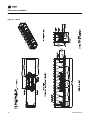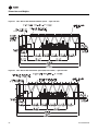
1
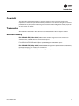
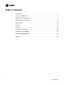
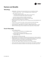
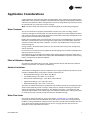
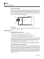
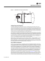
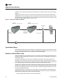
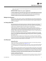
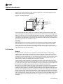
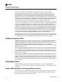
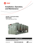
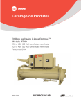
Product Catalog
Stealth™ Air-Cooled Chillers
Model RTAE
150 to 300 Nominal Tons
October 2014
RLC-PRC042D-EN
Introduction
Overview of Design
The Stealth™ air-cooled chiller was designed to meet the demanding requirements of today's
environment. The design transforms technology into performance on which you can depend.
Trane engineers brought innovation to every component in the next-generation Trane® Stealth
chiller. The result: the highest efficiency, improved system flexibility and performance, and the
lowest published sound levels—all while delivering improved reliability and lower maintenance
requirements.
At the core of the Stealth air-cooled chiller’s performance is AdaptiSpeed™ technology—the
integration of an all-new, direct-drive, specific-speed screw compressor; permanent magnet
motors and the Trane third-generation Adaptive Frequency™ drive, AFD3.
AdaptiSpeed Technology
AdaptiSpeed technology delivers unmatched efficiency with some of the lowest sound levels in the
industry.
•
Trane third-generation Adaptive Frequency™ drive (AFD3) – The AFD3 offers a part-load
efficiency improvement of more than 40 percent when compared to constant-speed chiller
designs.
•
Direct-drive, specific-speed screw compressor—Optimized for variable-speed operation, it
delivers peak efficiency under all operating conditions.
•
Variable Speed, Permanent magnet motors—The compressor’s and condenser fans’
permanent magnet motor design is up to 4 percent more efficient than conventional induction
motors.
© 2014 Trane All rights reserved
RLC-PRC042D-EN
Introduction
Copyright
This document and the information in it are the property of Trane, and may not be used or
reproduced in whole or in part without written permission. Trane reserves the right to revise this
publication at any time, and to make changes to its content without obligation to notify any person
of such revision or change.
Trademarks
All trademarks referenced in this document are the trademarks of their respective owners.
Revision History
RLC-PRC042D-EN (07 Oct 2014). Added 150T and 165T single circuit units, extreme low
ambient option, CE/PED, seismic and wind load options.
RLC-PRC042C-EN (30 May 2014). Added 200/60/3, 230/60/3 voltages. Added Transformer and
Line Voltage Harmonic Filtration options. Updated weights and isolator options.
RLC-PRC042B-EN (29 Sep 2013). Added 380/50/3 configuration. Updated electrical data tables,
field wiring drawing and made minor corrections.
RLC-PRC042-EN (06 Jun 2013). New catalog for RTAE product introduction.
RLC-PRC042D-EN
3
Table of Contents
Introduction . . . . . . . . . . . . . . . . . . . . . . . . . . . . . . . . . . . . . . . . . . . . . . . . . . . . . . 2
Features and Benefits . . . . . . . . . . . . . . . . . . . . . . . . . . . . . . . . . . . . . . . . . . . . . . 5
Application Considerations . . . . . . . . . . . . . . . . . . . . . . . . . . . . . . . . . . . . . . . . . . 7
Model Number Description . . . . . . . . . . . . . . . . . . . . . . . . . . . . . . . . . . . . . . . . . 14
General Data . . . . . . . . . . . . . . . . . . . . . . . . . . . . . . . . . . . . . . . . . . . . . . . . . . . . . 16
Controls . . . . . . . . . . . . . . . . . . . . . . . . . . . . . . . . . . . . . . . . . . . . . . . . . . . . . . . . 18
Electrical . . . . . . . . . . . . . . . . . . . . . . . . . . . . . . . . . . . . . . . . . . . . . . . . . . . . . . . . 24
Electrical Connections . . . . . . . . . . . . . . . . . . . . . . . . . . . . . . . . . . . . . . . . . . . . . 30
Dimensions and Weights . . . . . . . . . . . . . . . . . . . . . . . . . . . . . . . . . . . . . . . . . . 38
Mechanical Specifications . . . . . . . . . . . . . . . . . . . . . . . . . . . . . . . . . . . . . . . . . . 54
Options . . . . . . . . . . . . . . . . . . . . . . . . . . . . . . . . . . . . . . . . . . . . . . . . . . . . . . . . . 57
4
RLC-PRC042D-EN
Features and Benefits
Technology
•
AdaptiSpeed™ technology assures optimal performance at all operating conditions
• Permanent magnet motor - up to 4% more efficient than an induction motor
• AFD3 Adaptive Frequency™ Drive
• Soft start provided as standard to reduce power in-rush at start-up
• One of the first true 24 pulse drive systems in the industry
• Compressor design optimized for variable speed operation
• Rotor profile designed for maximum efficiency at higher speeds
•
Shuttle valve enhances compressor oil management
•
Variable speed permanent magnet motors on ALL condenser fans for increased efficiency and
lower sound
•
Larger diameter condenser fans operate at lower speed with optimized blade design
•
Compact, high-efficiency, integrated low refrigerant charge evaporator design
•
Integral compressor muffler lowers sound levels by 4-10 dB compared to previous design
•
Optional metallic discharge and suction bellows reduce compressor sound by 8-10 dB
Cost of Ownership
•
Industry-leading efficiency
• Over 20% higher full load efficiency than ASHRAE 90.1-2010
• Minimizing kW demand and infrastructure
• Over 40% higher part load efficiency than ASHRAE 90.1-2010
• Minimize kW usage
RLC-PRC042D-EN
•
Drive designed to last the life of the chiller
•
High power factor at all load points reducing the need for power factor correction capacitors
•
Variable speed drives on all condenser fans save energy at part load operation, as well as lower
sound levels even further as fan speeds are reduced during part load operation.
•
Transverse modular coil design for easy access for coil cleaning
•
Up to 40% lower refrigerant charge compared to previous evaporator designs
•
Factory-engineered, tested and installed sound control options reduce jobsite time and cost
•
Three levels of sound reduction available to meet various job site acoustical requirements
5
Features and Benefits
Reliability
•
Robust drive design using film capacitors for longer drive life
•
Industrial bearing system designed for the life of the chiller
•
Shuttle valve reduces the differential oil pressure required for cold weather start-up
•
New header design eliminates brazed coil u-bends, significantly reduces potential for
refrigerant leaks
•
All aluminum alloy coils reduce potential for corrosion
•
Enhanced factory-applied corrosion protection available
•
Rapid Restart capability minimizes downtime
•
Easy hookup to Uninterruptable Power Supply (UPS) for mission critical applications
Precision Control
•
•
New 7 inch color touch screen display with graphics
Powered by UC800 industry-leading control algorithms
• Enhanced flow management provides unmatched system performance in variable flow
water systems
•
Adaptive Control™ keeps the chiller running in extreme conditions
• Tight set point control
• Graphical trending
• Maximized chiller update
6
•
BACnet®, Modbus™, LonTalk®, communications protocol interface available without the need
for gateways
•
Optional condenser fan speed control to help meet preset nighttime sound requirements
RLC-PRC042D-EN
Application Considerations
Certain application constraints should be considered when sizing, selecting and installing Trane
RTAE chillers. Unit and system reliability is often dependent upon proper and complete compliance
with these considerations. Where the application varies from the guidelines presented, it should
be reviewed with your local Trane account manager.
Note: The terms water and solution are used interchangeably in the following paragraphs.
Water Treatment
The use of untreated or improperly treated water in chillers may result in scaling, erosion,
corrosion, and algae or slime buildup. This will adversely affect heat transfer between the water
and system components. Proper water treatment must be determined locally and depends on the
type of system and local water characteristics.
Neither salt nor brackish water is recommend for use in Trane air-cooled RTAE chillers. Use of either
will lead to a shortened life. Trane encourages the employment of a qualified water treatment
specialist, familiar with local water conditions, to assist in the establishment of a proper water
treatment program.
Foreign matter in the chilled water system can also increase pressure drop and, consequently,
reduce water flow.
For this reason it is important to thoroughly flush all water piping to the unit before making the final
piping connections to the unit.
The capacities given in the Performance Data section of this catalog are based on water with a
fouling factor of 0.0001°F·ft²·h/Btu (in accordance with AHRI 550/590). For capacities at other fouling
factors, see Performance Selection Software.
Effect of Altitude on Capacity
At elevations substantially above sea level, the decreased air density will decrease condenser
capacity and, therefore, unit capacity and efficiency.
Ambient Limitations
Trane chillers are designed for year-round operation over a range of ambient temperatures. The aircooled model RTAE chiller will operate in ambient temperatures of:
•
Standard Ambient Range = 32 to 105°F (0 to 40.6°C)
•
Low Ambient Range = 0 to 105°F (-17.7 to 40.6°C)
•
Extreme Low Ambient Range = -20 to 105°F (-28.9 to 40.6°C)
•
High Ambient Range = 32 to 125°F (0 to 52°C)
•
Wide Ambient Range = 0 to 125°F (-17.7 to 52°C)
The minimum ambient temperatures are based on still conditions (winds not exceeding five mph).
Greater wind speeds will result in a drop in head pressure, therefore increasing the minimum
starting and operating ambient temperature. The Adaptive Frequency™ microprocessor will
attempt to keep the chiller on-line when high or low ambient conditions exist, making every effort
to avoid nuisance trip-outs and provide the maximum allowable tonnage.
Water Flow Limits
The minimum water flow rates are given in the chapter “General Data,” p. 16 of this catalog.
Evaporator flow rates below the tabulated values will result in laminar flow causing freeze-up
problems, scaling, stratification and poor control. The maximum evaporator water flow rate is also
given. Flow rates exceeding those listed may result in very high pressure drop across the
evaporator and/or evaporator tube erosion.
RLC-PRC042D-EN
7
Application Considerations
Flow Rates Out of Range
Many process cooling jobs require flow rates that cannot be met with the minimum and maximum
published values within the RTAE evaporator. A simple piping change can alleviate this problem.
For example: a plastic injection molding process requires 80 gpm (5.0 l/s) of 50°F (10°C) water and
returns that water at 60°F (15.6°C). The selected chiller can operate at these temperatures, but has
a minimum flow rate of 106 gpm (6.6 l/s). The system layout in Figure 1 can satisfy the process.
Figure 1.
Flow rate out of range systems solution
50°F (10°C)
80 gpm (5 l/s)
50°F (10°C)
114 gpm (7 l/s)
PUMP
50°F (10°C)
32 gpm (2 l/s)
LOAD
57°F (14°C)
114 gpm (7 l/s)
PUMP
60°F (15.6°C)
80 gpm (5 l/s)
Flow Proving
Trane provides a factory-installed water flow switch monitored by UC800 which protects the chiller
from operating in loss of flow conditions.
Water Temperature
Leaving Water Temperature Limits
Trane RTAE chillers have three distinct leaving water categories:
•
Standard, with a leaving solution range of 40 to 68°F (4.4 to 20°C)
•
Low temperature process cooling, with leaving solution less than 40°F (4.4°C)
•
Ice-making, with a leaving solution range of 20 to 68°F (-6.7 to 20°C)
Since leaving solution temperatures below 40°F (4.4°C) result in suction temperature at or below
the freezing point of water, a glycol solution is required for all low temperature and ice-making
machines. Ice making control includes dual setpoints and safeties for ice making and standard
cooling capabilities. Consult your local Trane account manager for applications or selections
involving low temperature or ice making machines.
The maximum water temperature that can be circulated through the RTAE evaporator when the
unit is not operating is 125°F (52°C). Evaporator damage may result above this temperature.
Leaving Water Temperature Out of Range
Many process cooling jobs require temperature ranges that are outside the allowable minimum
and maximum operating values for the chiller. Figure 2 below shows a simple example of a mixed
water piping arrangement change that can permit reliable chiller operation while meeting such
cooling conditions. For example, a laboratory load requires 238 gpm (15 l/s) of water entering the
process at 86°F (30°C) and returning at 95°F (35°C). The chiller’s maximum leaving chilled water
temperature of 68°F (20°C) prevents direct supply to the load. In the example shown, both the chiller
and process flow rates are equal, however, this is not necessary. For example, if the chiller had a
higher flow rate, there would simply be more water bypassing and mixing with warm water
returning to the chiller.
8
RLC-PRC042D-EN
Application Considerations
Figure 2.
Temperature out of range system solution
59°F
(15°C)
60 gpm
(3.8 l/s)
59°F(15°C)
238 gpm (15 l/s)
68°F (20°C)
238 gpm (15 l/s)
80°F
(30°C)
238 gpm
(15 l/s)
PUMP
95°F
(35°C)
178 gpm
(11.2 l/s)
LOAD
59°F
(15°C)
178 gpm
(11.2 l/s)
PUMP
95°F
(35°C)
60 gpm
(3.8 l/s)
95°F (35°C)
238 gpm (15 l/s)
Variable Flow in the Evaporator
An attractive chilled water system option may be a variable primary flow (VPF) system. VPF
systems present building owners with several cost saving benefits that are directly related to the
pumps. The most obvious cost savings result from eliminating the secondary distribution pump,
which in turn avoids the expense incurred with the associated piping connections (material, labor),
electrical service, and variable frequency drive. Building owners often cite pump related energy
savings as the reason that prompted them to install a VPF system.
The evaporator on the Stealth can withstand up to 50 percent water flow reduction as long as this
flow is equal to or above the minimum flow rate requirements. The microprocessor and capacity
control algorithms are designed to handle a maximum of 10% change in water flow rate per minute
in order to maintain ± 0.5°F (0.28°C) leaving evaporator temperature control. For applications in
which system energy savings is most important and tight temperature control is classified as +/2°F (1.1°C), up to 30 percent changes in flow per minute are possible.
With the help of a software analysis tool such as System Analyzer™, DOE-2 or TRACE™, you can
determine whether the anticipated energy savings justify the use of variable primary flow in a
particular application. It may also be easier to apply variable primary flow in an existing chilled
water plant. Unlike the "decoupled" system design, the bypass can be positioned at various points
in the chilled water loop and an additional pump is unnecessary.
Series Chiller Arrangements
Another energy saving strategy is to design the system around chillers arranged in series. The
actual savings possible with such strategies depends on the application dynamics and should be
researched by consulting your Trane Systems Solutions Representative and applying an analysis
tool from the Trace software family. It is possible to operate a pair of chillers more efficiently in a
series chiller arrangement than in a parallel arrangement. It is also possible to achieve higher
entering to leaving chiller differentials, which may, in turn, provide the opportunity for lower chilled
water design temperature, lower design flow, and resulting installation and operational cost
savings. The Trane screw compressor also has excellent capabilities for “lift,” which affords an
opportunity for “lift,” which affords an opportunity for savings on the evaporator water loop.
Series chiller arrangements can be controlled in several ways. Figure 3, p. 10 shows a strategy
where each chiller is trying to achieve the system design set point. If the cooling load is less than
50 percent of the systems capabilities, either chiller can fulfill the demand. As system loads
increase, the Chiller 2 becomes preferentially loaded as it attempts to meet the leaving chilled water
RLC-PRC042D-EN
9
Application Considerations
setpoint. Chiller 1 will finish cooling the leaving water from Chiller 2 down to the system design
setpoint.
Staggering the chiller set points is another control technique that works well for preferentially
loading Chiller 1. If the cooling load is less than 50 percent of the system capacity, Chiller 1 would
be able to satisfy the entire call for cooling. As system loads increase, Chiller 2 is started to meet
any portion of the load that Chiller 1 can not meet.
Figure 3. Typical series chiller arrangement
Chiller 2
Setpoint = 42°F (5.6°C)
Chiller 1
Setpoint = 42°F (5.6°C)
Blending
Valve
Variable
depending
on load
58°F
(14.4°C)
42°F (5.6°C)
Typical Water Piping
All building water piping must be flushed prior to making final connections to the chiller. To reduce
heat loss and prevent condensation, insulation should be applied. Expansion tanks are also usually
required so that chilled water volume changes can be accommodated.
Avoidance of Short Water Loops
Adequate chilled water system water volume is an important system design parameter because it
provides for stable chilled water temperature control and helps limit unacceptable short cycling of
chiller compressors.
The chiller’s temperature control sensor is located in the waterbox. This location allows the
building to act as a buffer to slow the rate of change of the system water temperature. If there is
not a sufficient volume of water in the system to provide an adequate buffer, temperature control
can suffer, resulting in erratic system operation and excessive compressor cycling.
Typically, a two-minute water loop circulation time is sufficient to prevent short water loop issues.
Therefore, as a guideline, ensure the volume of water in the chilled water loop equals or exceeds
two times the evaporator flow rate. For systems with a rapidly changing load profile the amount
of volume should be increased.
If the installed system volume does not meet the above recommendations, the following items
should be given careful consideration to increase the volume of water in the system and, therefore,
reduce the rate of change of the return water temperature.
•
10
A volume buffer tank located in the return water piping.
RLC-PRC042D-EN
Application Considerations
•
Larger system supply and return header piping (which also reduces system pressure drop and
pump energy use).
Minimum water volume for a process application
If a chiller is attached to an on/off load such as a process load, it may be difficult for the controller
to respond quickly enough to the very rapid change in return solution temperature if the system
has only the minimum water volume recommended. Such systems may cause chiller low
temperature safety trips or in the extreme case evaporator freezing. In this case, it may be
necessary to add or increase the size of the mixing tank in the return line.
Multiple Unit Operation
Whenever two or more units are used on one chilled water loop, Trane recommends that their
operation be coordinated with a higher level system controller for optimum system efficiency and
reliability. The Trane Tracer system has advanced chilled plant control capabilities designed to
provide such operation.
Ice Storage Operation
An ice storage system uses the chiller to make ice at night when utilities generate electricity more
efficiently with lower demand and energy charges. The stored ice reduces or even replaces
mechanical cooling during the day when utility rates are at their highest. This reduced need for
cooling results in significant utility cost savings and source energy savings.
Another advantage of an ice storage system is its ability to eliminate chiller over sizing. A
“rightsized” chiller plant with ice storage operates more efficiently with smaller support equipment
while lowering the connected load and reducing operating costs. Best of all this system still
provides a capacity safety factor and redundancy by building it into the ice storage capacity for
practically no cost compared to over sized systems.
The Trane air-cooled chiller is uniquely suited to low temperature applications like ice storage
because of the ambient relief experienced at night. Chiller ice making efficiencies are typically
similar to or even better than standard cooling daytime efficiencies as a result of night-time drybulb ambient relief.
Standard smart control strategies for ice storage systems are another advantage of the RTAE
chiller. The dual mode control functionality is integrated right into the chiller. Trane Tracer building
management systems can measure demand and receive pricing signals from the utility and decide
when to use the stored cooling and when to use the chiller.
Unit Placement
Setting The Unit
A base or foundation is not required if the selected unit location is level and strong enough to
support the unit’s operating weight. (See “Weights,” p. 38.)
For a detailed discussion of base and foundation construction, see the sound engineering bulletin
or the unit IOM. Manuals are available through online product portal pages or from your local
office.
HVAC equipment must be located to minimize sound and vibration transmission to the occupied
spaces of the building structure it serves. If the equipment must be located in close proximity to
a building, it should be placed next to an unoccupied space such as a storage room, mechanical
room, etc. It is not recommended to locate the equipment near occupied, sound sensitive areas of
the building or near windows. Locating the equipment away from structures will also prevent
sound reflection, which can increase sound levels at property lines or other sensitive points.
Isolation and Sound Emission
Structurally transmitted sound can be reduced by elastomeric vibration eliminators. Elastomeric
isolators are generally effective in reducing vibratory noise generated by compressors, and
RLC-PRC042D-EN
11
Application Considerations
therefore, are recommended for sound sensitive installations. An acoustical engineer should
always be consulted on critical applications.
Figure 4. Installation example
Piping isolation
Chilled water piping
should be supported
Isolators
Isolators
Concrete Base
Flexible
electrical
conduit
For maximum isolation effect, water lines and electrical conduit should also be isolated. Wall
sleeves and rubber isolated piping hangers can be used to reduce sound transmitted through water
piping. To reduce the sound transmitted through electrical conduit, use flexible electrical conduit.
Local codes on sound emissions should always be considered. Since the environment in which a
sound source is located affects sound pressure, unit placement must be carefully evaluated. Sound
power levels for chillers are available on request.
Servicing
Adequate clearance for evaporator, condenser and compressor servicing should be provided.
Recommended minimum space envelopes for servicing are located in the dimensional data
section and can serve as a guideline for providing adequate clearance. The minimum space
envelopes also allow for control panel door swing and routine maintenance requirements. Local
code requirements may take precedence.
Unit Location
General
Unobstructed flow of condenser air is essential to maintain chiller capacity and operating
efficiency. When determining unit placement, careful consideration must be given to assure a
sufficient flow of air across the condenser heat transfer surface. Two detrimental conditions are
possible and must be avoided: warm air recirculation and coil starvation. Air recirculation occurs
when discharge air from the condenser fans is recycled back to the condenser coil inlet. Coil
starvation occurs when free airflow to the condenser is restricted.
Condenser coils and fan discharge must be kept free of snow or other obstructions to permit
adequate airflow for satisfactory unit operation. Debris, trash, supplies, etc., should not be allowed
to accumulate in the vicinity of the air-cooled chiller. Supply air movement may draw debris into
the condenser coil, blocking spaces between coil fins and causing coil starvation.
Both warm air recirculation and coil starvation cause reductions in unit efficiency and capacity due
to higher head pressures. The air-cooled RTAE chiller offers an advantage over competitive
equipment in these situations. Operation is minimally affected in many restricted air flow situations
due to its advanced Adaptive Control™ microprocessor which has the ability to understand the
operating environment of the chiller and adapt to it by first optimizing its performance and then
staying on line through abnormal conditions. For example, high ambient temperatures combined
with a restricted air flow situation will generally not cause the air-cooled model RTAE chiller to shut
down. Other chillers would typically shut down on a high pressure nuisance cut-out in these
conditions.
12
RLC-PRC042D-EN
Application Considerations
Cross winds, those perpendicular to the condenser, tend to aid efficient operation in warmer
ambient conditions. However, they tend to be detrimental to operation in lower ambients due to
the accompanying loss of adequate head pressure. Special consideration should be given to low
ambient units. As a result, it is advisable to protect air-cooled chillers from continuous direct winds
exceeding 10 mph (4.5 m/s) in low ambient conditions.
The recommended lateral clearances are depicted in the Close-Spacing and Restricted Airflow
Engineering Bulletin RLC-PRB037*-EN available on product portal pages or from your local office.
Provide Sufficient Unit-to-Unit Clearance
Units should be separated from each other by sufficient distance to prevent warm air recirculation
or coil starvation. Doubling the recommended single unit air-cooled chiller clearances will
generally prove to be adequate. See Close-Spacing and Restricted Airflow Engineering Bulletin
RLC-PRB037*-EN for more information.
Walled Enclosure Installations
When the unit is placed in an enclosure or small depression, the top of the surrounding walls
should be no higher than the top of the fans. The chiller should be completely open above the fan
deck. There should be no roof or structure covering the top of the chiller. Ducting individual fans
is not recommended. See Close-Spacing and Restricted Airflow Engineering Bulletin RLCPRB037*-EN for more information.
RLC-PRC042D-EN
13
Model Number Description
Digits 1,2 — Unit Model
Digit 16 — Evaporator
Application
Digit 26 — Power Line
Connection Type
Digits 3— Unit Type
F
=
A
G
=
A
C
D
C
=
RT =
=
Rotary Chiller
Air-cooled
Digits 4 — Development
Sequence
E
=
Development Sequence
Digits 5-7 — Nominal Capacity
149 =
164 =
150 =
165 =
180 =
200 =
225 =
250 =
275 =
300 =
150 Nominal Tons Single Circuit
165 Nominal Tons Single Circuit
150 Nominal Tons
165 Nominal Tons
180 Nominal Tons
200 Nominal Tons
225 Nominal Tons
250 Nominal Tons
275 Nominal Tons
300 Nominal Tons
Standard Cooling
(40 to 68°F/5.5 to 20°C)
Low Temp Process
(<40°F Leaving Temp)
Ice-making (20 to 68°F/-7 to 20°C)
w/ Hardwired Interface
Digit 17 — Evaporator
Configuration
N
P
=
=
2 Pass Evaporator
3 Pass Evaporator
Digit 18 — Evaporator Fluid Type
1
2
3
4
5
=
=
=
=
=
Water
Calcium Chloride
Ethylene Glycol
Propylene Glycol
Methanol
Digit 8— Unit Voltage
Digit 19 — Water Connection
A
B
C
D
E
F
G
H
X
F
=
=
=
=
=
=
=
=
200/60/3
230/60/3
380/50/3
380/60/3
400/50/3
460/60/3
575/60/3
400/60/3
Digit 9 — Manufacturing
Location
U
=
Trane Commercial Systems,
Pueblo, CO USA
Digits 10, 11— Design Sequence
XX =
=
=
3
=
InvisiSound™ Standard Unit
InvisiSound Superior
(Line Wraps, Reduced Fan Speed)
InvisiSound Ultimate
(Compressor Sound Attenuation,
Line Wraps, Reduced Fan Speed)
1
=
2
=
3
=
A
=
B
=
0
1
=
=
No Transformer
Factory Installed Transformer
Digit 29 — Line Voltage
Harmonic Mitigation
X
1
=
=
Line Reactors (~30% TDD)
Filter circuit (IEEE519 Compliant)
Digit 30 — Electrical Accessories
0
C
=
=
No Convenience Outlet
15A 115V convenience Outlet
(Type B)
Digit 31 — Remote
Communication Options
0
=
1
=
2
=
3
=
No Remote Digital
Communication
LonTalk® Interface LCI-C
(Tracer™ Compatible)
BACnet® MS/TP Interface
(Tracer compatible)
ModBus™ Interface
Digit 32 — Hard Wire
Communication
F
G
=
=
Digit 23 — Condenser Fin
Options
H
=
A
D
Digit 33 — Not Used
4
=
0
A
C
5
=
=
=
Digit 28 — Transformer
=
=
Digit 13 — Agency Listing
L
P
Default A Short Circuit Rating
High A Short Circuit Rating
D
E
=
ASME Pressure Vessel Code
Australia Pressure Vessel Code
CRN or Canada Equivalent
Pressure Vessel Code
Chinese Pressure Vessel Code
PED European Pressure Vessel
Code
=
=
=
3
=
=
=
A
B
C
Digit 22 — Unit Application
=
A
D
C
Digit 27 — Short Circuit Current
Rating
=
=
=
2
Digit 14 — Pressure Vessel Code
Factory Insulation - All Cold Parts
0.75”
Evaporator-Only Insulation High Humidity/Low Evap Temp
1.25”
Terminal Block
Circuit Breaker
Circuit Breaker w/ High Fault
Rated Control Panel
X
A
B
=
No Agency Listing
UL/CUL Listing
CE European Safety Standard
Factory Installed - Other Fluid
(15 cm/s)
Factory Installed - Water 2
(35 cm/s)
Factory Installed - Water 3
(45 cm/s)
Digit 21 — Insulation
1
=
=
=
Grooved Pipe
Grooved Pipe + Flange
Digit 20 — Flow Switch
Factory assigned
Digit 12 — Unit Sound Package
1
2
=
=
=
=
=
=
=
Standard Ambient
(32 to 105°F/0 to 40.6°C)
Low Ambient
(0 to 105°F/-17.7 to 40.6°C)
Extreme Low Ambient
(-20 to 105°F/-28.9 to 40.6°C)
High Ambient
(32 to 125°F/0 to 52°C)
Wide Ambient
(0 to 125°F/-17.7 to 52°C)
Aluminum Fins with Slits
CompleteCoat™ Epoxy Coated
Fins
None
Hard Wired Bundle - All
Remote Leaving Water Temp
Setpoint
Remote Leaving temp and
Demand Limit Setpoints
Programmable Relay
Programmable Relay and
Leaving Water and Demand Limit
Setpoint
Percent Capacity
Percent Capacity and Leaving
Water and Demand Limit Setpoint
Percent Capacity and
Programmable Relay
Digits 24, 25 — Not Used
Digit 15 — Factory Charge
1
2
14
=
=
Refrigerant Charge HFC-134a
Nitrogen Charge
RLC-PRC042D-EN
Model Number Description
Digit 34 — Structural Options
A
B
=
=
C
=
D
=
E
F
=
=
Standard Unit Structure
Seismic to International Building
Code (IBC)
California Office of Statewide
Health Planning and
Development (OSHPD)
Certification
Wind Load for Florida Hurricane
175 MPH
Seismic (IBC) and Wind Load
OSHPD and Wind Load
Digit 35 — Appearance Options
0
A
=
=
No Appearance Options
Architectural Louvered Panels
Digit 36 — Unit Isolation
0
1
3
=
=
=
No Isolation
Elastomeric Isolators
Seismic Rated Isopads
Digit 37 — Not Used
0
=
Not Used
Digit 38 — Not Used
0
=
Not Used
Digit 39 — Special
0
S
=
=
None
Special
RLC-PRC042D-EN
15
General Data
Table 1.
General data table
Unit Size (tons)
150
165
180
200
225
250
275
300
150SC
165SC
CHHSR
CHHSR
CHHSR
CHHSR
CHHSS
CHHSS
CHHSS
CHHSS
CHHSS
CHHSS
#
2
2
2
2
2
2
2
2
1
1
(gal)
17.5
18.7
21.9
23.9
26.6
28.7
33.0
36.0
17.3
17.3
(L)
66.1
70.9
82.8
90.5
100.6
108.8
125.0
136.1
65.6
65.6
Compressor Model
Quantity
Evaporator
Water Storage
2 Pass arrangement
Minimum Flow
Maximum Flow
(gpm)
171
187
202
228
261
288
318
354
169
169
(l/s)
10.8
11.8
12.7
14.4
16.5
18.2
20.1
22.3
10.7
10.7
(gpm)
626
684
742
835
957
1055
1165
1299
620
620
(l/s)
39.5
43.1
46.8
52.7
60.4
66.5
73.5
81.9
39.1
39.1
(gpm)
114
124
135
152
174
192
212
236
113
113
(l/s)
7.2
7.8
8.5
9.6
11.0
12.1
13.4
14.9
7.1
7.1
(gpm)
417
456
495
557
638
703
777
866
414
414
(l/s)
26.3
28.8
31.2
35.1
40.2
44.3
49.0
54.6
26.1
26.1
8
10
10
12
12
12
14
16
8
10
(in)
78.74
78.74
78.74
78.74
78.74
78.74
78.74
78.74
78.74
78.74
(mm)
2000
2000
2000
2000
2000
2000
2000
2000
2000
2000
(in)
50
50
50
50
50
50
50
50
50
50
(mm)
1270
1270
1270
1270
1270
1270
1270
1270
1270
1270
192
192
192
192
192
192
192
192
192
192
3
3
3
3
3
3
3
3
3
3
3 Pass arrangement
Minimum Flow
Maximum Flow
Condenser
Qty of Coils
Coil Length
Coil Height
Fins/Ft
Rows
Condenser Fans
Quantity
#
8
10
10
12
12
12
14
16
8
10
Diameter
(in)
37.5
37.5
37.5
37.5
37.5
37.5
37.5
37.5
37.5
37.5
Total Airflow
(mm)
953
953
953
953
953
953
953
953
953
953
(cfm)
107,392
134,240
134,240
161,088
161,088
161,088
187,936
214,784
107,392
132,240
(m3/hr)
182,460
228,075
228,075
273,690
273,690
273,690
319,305
364,920
182,460
228,075
8700
8700
8700
8700
8700
8700
8700
8700
8700
8700
44.2
44.2
44.2
44.2
44.2
44.2
44.2
44.2
44.2
44.2
Tip Speed (ft/min)
(M/S)
Ambient Temperature Range
Standard Ambient °F (°C)
32 to 105 (0 to 40.6)
Low Ambient °F (°C)
0 to 105 (-17.7 to 40.6)
Extreme Low Ambient °F (°C)
-20 to 105 (-28.9 to 40.6)
High Ambient °F (°C)
32 to 125 (0 to 52)
Wide Ambient °F (°C)
0 to 125 (-17.7 to 52)
General Unit
Refrigerant
HFC-134a
#
Minimum Load
%
20
18
17
15
20
18
16
15
30
27
(lbs)
172
181
210
218
265
261
318
325
322
346
(kg)
78
82
95
99
120
118
144
148
146
157
Refrigerant Charge/ckt
2
Oil
Oil Charge/ckt
16
HFC-134a
Refrigerant Ckts
1
Trane OIL00311
(gal)
3.0
3.0
3.0
3.0
4.0
4.0
4.0
4.0
4.0
4.0
(L)
11.4
11.4
11.4
11.4
15.1
15.1
15.1
15.1
15.1
15.1
RLC-PRC042D-EN
General Data
Table 2.
Drive cooling
Unit Size (tons)
Extended Length Units(a)
Standard Length Unit
150S - 165S
150
165-250
Drive Cooling Fluid Type
275-300
150S - 165S
150
165-250
275-300
Trane Heat Transfer Fluid CHM01023
Fluid Volume (gal)
Ckt 1
1.28
1.14
1.23
1.32
1.37
1.30
1.32
1.41
Ckt2
n/a
1.32
1.67
1.81
n/a
1.67
1.81
1.95
Total
1.28
2.46
2.89
3.12
1.37
2.97
3.12
3.36
Ckt1
4.86
4.30
4.64
4.98
5.20
4.93
4.98
5.33
Ckt2
n/a
5.01
6.31
6.84
n/a
6.31
6.84
7.38
Total
4.86
9.31
10.95
11.83
5.20
11.23
11.83
12.71
Fluid Volume (l)
(a) Units are extended length if either of the following are selected:
Transformer (model number digit 28 = 1)
Harmonic Filtration Option (model number digit 29 = 1)
Units without Harmonic Filtration Option or Transformer (digits 28, 29 = 0X) are standard length.
RLC-PRC042D-EN
17
Controls
Tracer UC800 Controller
Today’s Stealth™ chillers offer predictive controls that anticipate and compensate for load changes.
Other control strategies made possible with the Tracer UC800 controls are:
Feedforward Adaptive Control
Feedforward is an open-loop, predictive control strategy designed to anticipate and compensate
for load changes. It uses evaporator entering-water temperature as an indication of load change.
This allows the controller to respond faster and maintain stable leaving-water temperatures.
Soft Loading
The chiller controller uses soft loading except during manual operation. Large adjustments due to
load or setpoint changes are made gradually, preventing the compressor from cycling
unnecessarily. It does this by internally filtering the setpoints to avoid reaching the differential-tostop or the demand limit. Soft loading applies to the leaving chilled-water temperature and demand
limit setpoints.
Adaptive Controls
Adaptive Controls directly sense the control variables that govern the operation of the chiller:
evaporator pressure and condenser pressure. When any one of these variables approaches a limit
condition when damage may occur to the unit or shutdown on a safety, Adaptive Controls takes
corrective action to avoid shutdown and keep the chiller operating. This happens through
combined actions of compressor and/or fan staging. Whenever possible, the chiller is allowed to
continue making chilled water. This keeps cooling capacity available until the problem can be
solved. Overall, the safety controls help keep the building or process running and out of trouble.
Rapid Restart
A Rapid Restart is performed after a momentary power loss occurs during operation. Similarly,
if the chiller shuts down on a non-latching diagnostic and the diagnostic later clears itself, a Rapid
Restart will be initiated.
AdaptiSpeed Control
Compressor speed is used to control capacity of the chiller, optimizing mathematically with the
condenser fan speed to provide the highest level of performance. The increased performance of
the UC800 Controller allows the chiller to operate longer at higher efficiency, and with greater
stability.
Variable-Primary Flow (VPF)
Chilled-water systems that vary the water flow through chiller evaporators have caught the
attention of engineers, contractors, building owners, and operators. Varying the water flow
reduces the energy consumed by pumps, while having limited affect on the chiller energy
consumption. This strategy can be a significant source of energy savings, depending on the
application.
18
RLC-PRC042D-EN
Controls
Tracer AdaptiView TD7 Operator Interface
The standard Tracer AdaptiView™ TD7 display provided with the Trane UC800 controller features
a 7” LCD touch-screen, allowing access to all operational inputs and outputs. This is an advanced
interface that allows the user to access any important information concerning setpoints, active
temperatures, modes, electrical data, pressure, and diagnostics. It uses full text display available
in 26 languages.
Display Features Include:
•
LCD touch-screen with LED backlighting, for scrolling access to input and output operating
information
•
Single-screen, folder/tab-style display of all available information on individual components
(evaporator, condenser, compressor, etc.)
•
Manual override indication
•
Password entry/lockout system to enable or disable display
•
Automatic and immediate stop capabilities for standard or immediate manual shutdown
•
Fast, easy access to available chiller data in tabbed format, including:
• Easy to view Operating Modes
• Logical Sub-Component Reports:
• Evaporator
• Condenser
• Compressor
• Motor
• 3 User Programmable Custom Reports
• ASHRAE report
• Logsheet Report
• Alarms Report
• 8 pre-defined Standard Graphs
• 4 User Programmable Custom Graphs
• Chiller Settings
• Feature Settings
• Chilled Water Reset
• Manual Control Settings
• Globalization Settings
• Support of 26 languages
• Brightness Setting
• Cleaning Mode
RLC-PRC042D-EN
19
Controls
Tracer TU Interface
Tracer™ TU (non-Trane personnel, contact your local Trane office for software) adds a level of
sophistication that improves service technician effectiveness and minimizes chiller downtime. The
Tracer AdaptiView™ control’s operator interface is intended to serve only typical daily tasks. The
portable PC-based service-tool software, Tracer TU, supports service and maintenance tasks.
Tracer TU serves as a common interface to all Trane® chillers, and will customize itself based on
the properties of the chiller with which it is communicating. Thus, the service technician learns only
one service interface.
The panel bus is easy to troubleshoot using LED sensor verification. Only the defective device is
replaced. Tracer TU can communicate with individual devices or groups of devices.
All chiller status, machine configuration settings, customizable limits, and up to 100 active or
historic diagnostics are displayed through the service-tool software interface.
LEDs and their respective Tracer TU indicators visually confirm the availability of each connected
sensor, relay, and actuator.
Tracer TU is designed to run on a customer’s laptop, connected to the Tracer AdaptiView control
panel with a USB cable. Your laptop must meet the following hardware and software requirements:
• 1 GB RAM (minimum)
•
•
•
•
•
1024 x 768 screen resolution
CD-ROM drive
Ethernet 10/100 LAN card
An available USB 2.0 port
Microsoft® Windows® XP Professional operation system with Service Pack 3 (SP3) or
Windows 7 Enterprise or Professional operating system (32-bit or 64-bit)
• Microsoft .NET Framework 4.0 or later
Note: Tracer TU is designed and validated for this minimum laptop configuration. Any variation
from this configuration may have different results. Therefore, support for Tracer TU is
limited to only those laptops with the configuration previously specified.
20
RLC-PRC042D-EN
Controls
System Integration
Stand-Alone Controls
Single chillers installed in applications without a building management system are simple to install
and control: only a remote auto/stop for scheduling is required for unit operation. Signals from the
chilled-water pump contactor auxiliary, or a flow switch, are wired to the chilled-water flow
interlock. Signals from a time clock or some other remote device are wired to the external auto/stop
input.
•
Auto/Stop - A job-site provided contact closure turns the unit on and off.
•
Emergency Stop - A job-site provided contact opening wired to this input turns the unit off and
requires a manual reset of the unit microcomputer. This closure is typically triggered by a jobsite provided system such as a fire alarm.
Hardwire Points
Microcomputer controls allow simple interface with other control systems, such as time clocks,
building automation systems, and ice storage systems via hardwire points. This means you have
the flexibility to meet job requirements while not having to learn a complicated control system.
Remote devices are wired from the control panel to provide auxiliary control to a building
automation system. Inputs and outputs can be communicated via a typical 4–20 mA electrical
signal, an equivalent 2–10 Vdc signal, or by utilizing contact closures.
This setup has the same features as a stand-alone water chiller, with the possibility of having
additional optional features:
• Ice making control
• External chilled water setpoint, external demand limit setpoint
• Chilled water temperature reset
• Programmable relays - available outputs are: alarm-latching, alarm-auto reset, general
alarm, warning, chiller limit mode, compressor running, and Tracer control.
BACnet Interface
Tracer AdaptiView control can be configured for BACnet® communications at the factory or in the
field. This enables the chiller controller to communicate on a BACnet MS/TP network. Chiller
setpoints, operating modes, alarms, and status can be monitored and controlled through BACnet.
Tracer AdaptiView controls conform to the BACnet B-ASC profile as defined by ASHRAE 135-2004.
LonTalk Communications Interface (LCI-C)
The optional LonTalk® Communications Interface for Chillers (LCI-C) is available factory or field
installed. It is an integrated communication board that enables the chiller controller to
communicate over a LonTalk network. The LCI-C is capable of controlling and monitoring chiller
setpoints, operating modes, alarms, and status. The Trane LCI-C provides additional points beyond
the standard LONMARK® defined chiller profile to extend interoperability and support a broader
range of system applications. These added points are referred to as open extensions. The LCI-C is
certified to the LONMARK Chiller Controller Functional Profile 8040 version 1.0, and follows
LonTalk FTT-10A free topology communications.
Modbus Interface
Tracer AdaptiView control can be configured for Modbus™ communications at the factory or in the
field. This enables the chiller controller to communicate as a slave device on a Modbus network.
Chiller setpoints, operating modes, alarms, and status can be monitored and controlled by a
Modbus master device.
RLC-PRC042D-EN
21
Controls
Tracer SC
The Tracer SC ™system controller acts as the central coordinator for all individual equipment
devices on a Tracer building automation system. The Tracer SC scans all unit controllers to update
information and coordinate building control, including building subsystems such as VAV and
chiller water systems. With this system option, the full breadth of Trane’s HVAC and controls
experience are applied to offer solutions to many facility issues. The LAN allows building operators
to manage these varied components as one system from any personal computer with web access.
The benefits of this system are:
•
Improved usability with automatic data collection, enhanced data logging, easier to create
graphics, simpler navigation, pre-programmed scheduling, reporting, and alarm logs.
•
Flexible technology allows for system sizes from 30-120 unit controllers with any combination
of LonTalk or BACnet unit controllers.
•
LEED certification through site commissioning report, energy data collection measurement,
optimizing energy performance, and maintaining indoor air quality.
Energy savings programs include: fan pressure optimization, ventilation reset, and chiller plant
control (adds and subtracts chillers to meet cooling loads).
Building Automation and Chiller Plant Control
The UC800 controller can communicate with Trane Tracer SC and Tracer ES building automation
systems, which include pre-engineered and flexible control for chiller plants. These building
automation systems can control the operation of the complete installation: chillers, pumps,
isolating valves, air handlers, and terminal units. Trane can undertake full responsibility for
optimized automation and energy management for the entire chiller plant. The main functions are:
• Chiller sequencing: equalizes the number of running hours of the chillers. Different
control strategies are available depending on the configuration of the installation.
• Control of the auxiliaries: includes input/output modules to control the operation of the
various auxiliary equipment (water pumps, valves, etc.)
• Time-of-day scheduling: allows the end user to define the occupancy period, for example:
time of the day, holiday periods and exception schedules.
• Optimization of the installation start/stop time: based on the programmed schedule
of occupancy and the historical temperature records. Tracer SC calculates the optimal start/
stop time of the installation to get the best compromise between energy savings and
comfort of the occupants.
• Soft loading: the soft loading function minimizes the number of chillers that are operated
to satisfy a large chilled-water-loop pull down, thus preventing an overshoot of the actual
capacity required. Unnecessary starts are avoided and the peak current demand is lowered.
• Communication capabilities: local, through a PC workstation keyboard. Tracer SC can be
programmed to send messages to other local or remote workstations and or a pager in the
following cases:
• Analog parameter exceeding a programmed value
• Maintenance warning
• Component failure alarm
• Critical alarm messages. In this latter case, the message is displayed until the operator
acknowledges the receipt of the information. From the remote station it is also possible
to access and modify the chiller plants control parameters.
• Remote communication through a modem: as an option, a modem can be connected
to communicate the plant operation parameters through voice grade phone lines.
22
RLC-PRC042D-EN
Controls
A remote terminal is a PC workstation equipped with a modem and software to display the remote
plant parameters.
Integrated Comfort System (ICS)
The onboard Tracer chiller controller is designed to be able to communicate with a wide range of
building automation systems. In order to take full advantage of chiller’s capabilities, incorporate
your chiller into a Tracer SC building automation system.
But the benefits do not stop at the chiller plant. At Trane, we realize that all the energy used in your
cooling system is important. That is why we worked closely with other equipment manufacturers
to predict the energy required by the entire system. We used this information to create patented
control logic for optimizing HVAC system efficiency.
The building owners challenge is to tie components and applications expertise into a single reliable
system that provides maximum comfort, control, and efficiency. Trane Integrated Comfort systems
(ICS) are a concept that combines system components, controls, and engineering applications
expertise into a single, logical, and efficient system. These advanced controls are fully
commissioned and available on every piece of Trane® equipment, from the largest chiller to the
smallest VAV box. As a manufacturer, only Trane offers this universe of equipment, controls, and
factory installation and verification.
RLC-PRC042D-EN
23
Electrical
Electrical Data
Table 3.
Electrical data — 60 Hz — all ambients
AFD Input
Amps(a)
Unit
Size
150S
165S
150
165
180
200
24
Rated
Voltage(c) Comp A Comp B Qty(d)
Fans
Control VA(b)
kW
FLA
Without
With
Harmonic Filtration Harmonic Filtration
(model # digit 29 =X) (model # digit 29 =1)
MCA(e)
MOP(f)
200/60/3
221
-
8
2.05
2.7
1074
-
693
1000
230/60/3
221
-
8
2.05
2.7
1074
-
603
1000
380/60/3
268
-
8
2.05
3.3
574
-
365
600
400/60/3
254
-
8
2.05
3.1
574
-
347
500
460/60/3
221
-
8
2.05
2.7
574
-
302
500
575/60/3
221
-
8
2.05
2.7
1074
-
242
400
200/60/3
235
-
10
2.05
2.7
1074
-
745
120
230/60/3
235
-
10
2.05
2.7
1074
-
648
1000
380/60/3
285
-
10
2.05
3.3
574
-
393
600
400/60/3
270
-
10
2.05
3.1
574
-
373
600
460/60/3
235
-
10
2.05
2.7
574
-
324
500
575/60/3
235
-
10
2.05
2.7
1074
-
260
400
200/60/3
124
124
8
2.05
2.7
1394
-
722
1000
230/60/3
124
124
8
2.05
2.7
1394
-
613
800
380/60/3
151
151
8
2.05
3.3
894
1394
369
500
400/60/3
143
143
8
2.05
3.1
894
1394
350
450
460/60/3
124
124
8
2.05
2.7
894
1394
305
400
575/60/3
124
124
8
2.05
2.7
1394
-
246
350
200/60/3
130
130
10
2.05
2.7
1394
-
761
1000
230/60/3
130
130
10
2.05
2.7
1394
-
646
800
380/60/3
157
157
10
2.05
3.3
894
1394
392
500
400/60/3
150
150
10
2.05
3.1
894
1394
372
500
460/60/3
130
130
10
2.05
2.7
894
1394
323
450
575/60/3
130
130
10
2.05
2.7
1394
-
259
350
200/60/3
143
143
10
2.05
2.7
1394
-
830
1000
230/60/3
143
143
10
2.05
2.7
1394
-
704
1000
380/60/3
173
173
10
2.05
3.3
894
1394
427
600
400/60/3
165
165
10
2.05
3.1
894
1394
405
500
460/60/3
143
143
10
2.05
2.7
894
1394
352
450
575/60/3
143
143
10
2.05
2.7
1394
-
282
400
200/60/3
154
154
12
2.05
2.7
1394
-
901
1200
230/60/3
154
154
12
2.05
2.7
1394
-
765
1000
380/60/3
186
186
12
2.05
3.3
894
1394
463
600
400/60/3
177
177
12
2.05
3.1
894
1394
440
600
460/60/3
154
154
12
2.05
2.7
894
1394
383
500
575/60/3
154
154
12
2.05
2.7
1394
-
307
400
RLC-PRC042D-EN
Electrical
Table 3.
Electrical data — 60 Hz — all ambients (continued)
AFD Input
Amps(a)
Unit
Size
225
250
275
300
Rated
Voltage(c) Comp A Comp B Qty(d)
Fans
Control VA(b)
kW
FLA
Without
With
Harmonic Filtration Harmonic Filtration
(model # digit 29 =X) (model # digit 29 =1)
MCA(e)
MOP(f)
200/60/3
160
160
12
2.05
2.7
1434
-
933
1200
230/60/3
160
160
12
2.05
2.7
1434
-
792
1000
380/60/3
194
194
12
2.05
3.3
934
1434
480
600
400/60/3
184
184
12
2.05
3.1
934
1434
455
600
460/60/3
160
160
12
2.05
2.7
934
1434
396
500
575/60/3
160
160
12
2.05
2.7
1434
-
317
450
200/60/3
186
186
12
2.05
2.7
1434
-
1071
1200
230/60/3
186
186
12
2.05
2.7
1434
-
909
1200
380/60/3
225
225
12
2.05
3.3
934
1434
551
700
400/60/3
213
213
12
2.05
3.1
934
1434
523
700
460/60/3
186
186
12
2.05
2.7
934
1434
455
600
575/60/3
186
186
12
2.05
2.7
1434
-
364
500
200/60/3
199
199
14
2.05
2.7
1434
-
1153
1600
230/60/3
199
199
14
2.05
2.7
1434
-
978
1200
380/60/3
241
241
14
2.05
3.3
934
1434
593
800
400/60/3
229
229
14
2.05
3.1
934
1434
563
700
460/60/3
199
199
14
2.05
2.7
934
1434
489
600
575/60/3
199
199
14
2.05
2.7
1434
-
392
500
200/60/3
215
215
16
2.05
2.7
1434
-
1250
1600
230/60/3
215
215
16
2.05
2.7
1434
-
1061
1200
380/60/3
260
260
16
2.05
3.3
934
1434
643
800
400/60/3
247
247
16
2.05
3.1
934
1434
610
800
460/60/3
215
215
16
2.05
2.7
934
1434
531
700
575/60/3
215
215
16
2.05
2.7
1434
-
425
600
(a) All 200, 230 and 575V units consist of a voltage autotransformer with a 460V unit downstream. As a result, AFD input amp draws for these voltages are
the same as those of a corresponding 460V unit.
(b) Control VA includes operational controls only. It does not include evaporator heaters. A separate 115/60/1, 15 amp customer provided power connection
is required to power the evaporator heaters (150T-165T; 800 watts, 180T-300T; 1200 watts).
(c) Voltage Utilization Range: +/- 1-% of Rated voltage (use range): 200/60/3 (180-220), 230/60/3 (208-254), 380/60/3 (342-418), 400/60/3 (360-440),
400/50/3 (360-440), 460/60/3 (414-506), 575/60/3 (516-633)
(d) Number of fans is evenly distributed between the two chiller circuits.
(e) MCA - Minimum Circuit Ampacity - 125 percent of largest compressor VFD input plus 100 percent of all other loads for 380V, 400V, and 460V incoming
voltage. All other voltages need to have the 460V calculation reflected to the appropriate voltage.
(f) Max fuse or MOPD = 225 percent of largest compressor VFD input plus 100 percent of second compressor VFD input, plus sum of condenser fan FLA.
RLC-PRC042D-EN
25
Electrical
Table 4.
Electrical data — 50 Hz — all ambients
Fans
Control VA(a)
Qty(c)
kW
FLA
Without
With
Harmonic Filtration Harmonic Filtration
(model # digit 29 =X) (model # digit 29 =1)
8
2.05
3.3
AFD Input Amps
Unit
Size
150S
165S
150
165
180
200
225
250
275
300
Rated
Voltage(b) Comp A Comp B
380/50/3
268
-
574
-
MCA(d)
MOP(e)
365
600
400/50/3
254
-
8
2.05
3.1
574
-
347
500
380/50/3
285
-
10
2.05
3.3
574
-
393
600
400/50/3
270
-
10
2.05
3.1
574
-
373
600
380/50/3
151
151
8
2.05
3.3
894
1394
369
500
400/50/3
143
143
8
2.05
3.1
894
1394
350
450
380/50/3
157
157
10
2.05
3.3
894
1394
392
500
400/50/3
150
150
10
2.05
3.1
894
1394
372
500
380/50/3
173
173
10
2.05
3.3
894
1394
427
600
400/50/3
165
165
10
2.05
3.1
894
1394
405
500
380/50/3
186
186
12
2.05
3.3
894
1394
463
600
400/50/3
177
177
12
2.05
3.1
894
1394
440
600
380/50/3
194
194
12
2.05
3.3
934
1434
480
600
400/50/3
184
184
12
2.05
3.1
934
1434
455
600
380/50/3
225
225
12
2.05
3.3
934
1434
551
700
400/50/3
213
213
12
2.05
3.1
934
1434
523
700
380/50/3
241
241
14
2.05
3.3
934
1434
593
800
400/50/3
229
229
14
2.05
3.1
934
1434
563
700
380/50/3
260
260
16
2.05
3.3
934
1434
643
800
400/50/3
247
247
16
2.05
3.1
934
1434
610
800
(a) Control VA includes operational controls only. It does not include evaporator heaters. A seperate 115/60/1, 15 amp customer provided power connection is
required to power the evaporator heaters (150T-165T; 800 watts, 180T-300T; 1200 watts).
(b) Voltage Utilization Range: +/- 1-% of Rated voltage (use range): 200/60/3 (180-220), 230/60/3 (208-254), 380/60/3 (342-418), 400/60/3 (360-440),
400/50/3 (360-440), 460/60/3 (414-506), 575/60/3 (516-633)
(c) Number of fans is evenly distributed between the two chiller circuits.
(d) MCA - Minimum Circuit Ampacity - 125 percent of largest compressor VFD input plus 100 percent of all other loads
(e) Max fuse or MOPD = 225 percent of largest compressor VFD input plus 100 percent of second compressor VFD input, plus sum of condenser fan FLA.
26
RLC-PRC042D-EN
Electrical
Customer Wiring
Table 5.
Customer wire selection(a) — 60 Hz
Unit Size
Volt
Terminal Block
Circuit Breaker
Circuit Breaker - High Fault
200
(4) 2 AWG - 600MCM
n/a
(4) 3/0 AWG - 500MCM
230
(4) 2 AWG - 600MCM
n/a
(4) 3/0 AWG - 500MCM
380
(2) 4 AWG - 500MCM
(2) 4/0 AWG - 500MCM
(2) 4/0 AWG - 500MCM
400
(2) 4 AWG - 500MCM
(2) 4/0 AWG - 500MCM
(2) 4/0 AWG - 500MCM
460
(2) 4 AWG - 500MCM
(2) 4/0 AWG - 500MCM
(2) 4/0 AWG - 500MCM
575
(2) 4 AWG - 500MCM
(3) 3/0 AWG - 500MCM
(3) 3/0 AWG - 500MCM
200
(4) 2 AWG - 600MCM
n/a
(4) 3/0 AWG - 500MCM
150S
165S
150
165
180
200
225
RLC-PRC042D-EN
230
(4) 2 AWG - 600MCM
n/a
(4) 3/0 AWG - 500MCM
380
(2) 4 AWG - 500MCM
(2) 4/0 AWG - 500MCM
(2) 4/0 AWG - 500MCM
400
(2) 4 AWG - 500MCM
(2) 4/0 AWG - 500MCM
(2) 4/0 AWG - 500MCM
460
(2) 4 AWG - 500MCM
(2) 4/0 AWG - 500MCM
(2) 4/0 AWG - 500MCM
575
(2) 4 AWG - 500MCM
(3) 3/0 AWG - 500MCM
(3) 3/0 AWG - 500MCM
200
(4) 2 AWG - 600MCM
n/a
(4) 3/0 AWG - 500MCM
230
(4) 2 AWG - 600MCM
(3) 3/0 AWG - 500MCM
(3) 3/0 AWG - 500MCM
380
(2) 4 AWG - 500MCM
(2) 4/0 AWG - 500MCM
(2) 4/0 AWG - 500MCM
400
(2) 4 AWG - 500MCM
(2) 4/0 AWG - 500MCM
(2) 4/0 AWG - 500MCM
460
(2) 4 AWG - 500MCM
(2) 4/0 AWG - 500MCM
(2) 4/0 AWG - 500MCM
575
(2) 4 AWG - 500MCM
(3) 3/0 AWG - 500MCM
(3) 3/0 AWG - 500MCM
200
(4) 2 AWG - 600MCM
n/a
(4) 3/0 AWG - 500MCM
230
(4) 2 AWG - 600MCM
n/a
(4) 3/0 AWG - 500MCM
380
(2) 4 AWG - 500MCM
(2) 4/0 AWG - 500MCM
(2) 4/0 AWG - 500MCM
400
(2) 4 AWG - 500MCM
(2) 4/0 AWG - 500MCM
(2) 4/0 AWG - 500MCM
460
(2) 4 AWG - 500MCM
(2) 4/0 AWG - 500MCM
(2) 4/0 AWG - 500MCM
575
(2) 4 AWG - 500MCM
(3) 3/0 AWG - 500MCM
(3) 3/0 AWG - 500MCM
27
Electrical
Table 5.
Customer wire selection(a) — 60 Hz (continued)
Unit Size
Volt
Terminal Block
Circuit Breaker
Circuit Breaker - High Fault
200
(4) 2 AWG - 600MCM
n/a
(4) 3/0 AWG - 500MCM
230
(4) 2 AWG - 600MCM
n/a
(4) 3/0 AWG - 500MCM
380
(2) 4 AWG - 500MCM
(3) 3/0 AWG - 500MCM
(3) 3/0 AWG - 500MCM
400
(2) 4 AWG - 500MCM
(3) 3/0 AWG - 500MCM
(3) 3/0 AWG - 500MCM
460
(2) 4 AWG - 500MCM
(2) 4/0 AWG - 500MCM
(2) 4/0 AWG - 500MCM
575
(2) 4 AWG - 500MCM
(3) 3/0 AWG - 500MCM
(3) 3/0 AWG - 500MCM
200
(4) 2 AWG - 600MCM
n/a
(4) 3/0 AWG - 500MCM
250
275
300
230
(4) 2 AWG - 600MCM
n/a
(4) 3/0 AWG - 500MCM
380
(2) 4 AWG - 500MCM
(3) 3/0 AWG - 500MCM
(3) 3/0 AWG - 500MCM
400
(2) 4 AWG - 500MCM
(3) 3/0 AWG - 500MCM
(3) 3/0 AWG - 500MCM
460
(2) 4 AWG - 500MCM
(2) 4/0 AWG - 500MCM
(2) 4/0 AWG - 500MCM
575
(2) 4 AWG - 500MCM
(3) 3/0 AWG - 500MCM
(3) 3/0 AWG - 500MCM
200
(4) 2 AWG - 600MCM
n/a
(4) 2 AWG - 600MCM
230
(4) 2 AWG - 600MCM
n/a
(4) 2 AWG - 600MCM
380
(2) 4 AWG - 500MCM
(3) 3/0 AWG - 500MCM
(3) 3/0 AWG - 500MCM
400
(2) 4 AWG - 500MCM
(3) 3/0 AWG - 500MCM
(3) 3/0 AWG - 500MCM
460
(2) 4 AWG - 500MCM
(3) 3/0 AWG - 500MCM
(3) 3/0 AWG - 500MCM
575
(2) 4 AWG - 500MCM
(3) 3/0 AWG - 500MCM
(3) 3/0 AWG - 500MCM
(a) Field wire insulation temperature rating must be minimum 90°C unless otherwise specified.
28
RLC-PRC042D-EN
Electrical
Table 6.
Customer wire selection(a) — 50 Hz
Unit Size
Volt
Terminal Block
Circuit Breaker
Circuit Breaker - High Fault
380
(2) 4 AWG - 500MCM
(2) 4/0 AWG - 500MCM
(2) 4/0 AWG - 500MCM
400
(2) 4 AWG - 500MCM
(2) 4/0 AWG - 500MCM
(2) 4/0 AWG - 500MCM
380
(2) 4 AWG - 500MCM
(2) 4/0 AWG - 500MCM
(2) 4/0 AWG - 500MCM
400
(2) 4 AWG - 500MCM
(2) 4/0 AWG - 500MCM
(2) 4/0 AWG - 500MCM
380
(2) 4 AWG - 500MCM
(2) 4/0 AWG - 500MCM
(2) 4/0 AWG - 500MCM
400
(2) 4 AWG - 500MCM
(2) 4/0 AWG - 500MCM
(2) 4/0 AWG - 500MCM
380
(2) 4 AWG - 500MCM
(2) 4/0 AWG - 500MCM
(2) 4/0 AWG - 500MCM
400
(2) 4 AWG - 500MCM
(2) 4/0 AWG - 500MCM
(2) 4/0 AWG - 500MCM
380
(2) 4 AWG - 500MCM
(2) 4/0 AWG - 500MCM
(2) 4/0 AWG - 500MCM
400
(2) 4 AWG - 500MCM
(2) 4/0 AWG - 500MCM
(2) 4/0 AWG - 500MCM
380
(2) 4 AWG - 500MCM
(2) 4/0 AWG - 500MCM
(2) 4/0 AWG - 500MCM
400
(2) 4 AWG - 500MCM
(2) 4/0 AWG - 500MCM
(2) 4/0 AWG - 500MCM
380
(2) 4 AWG - 500MCM
(2) 4/0 AWG - 500MCM
(2) 4/0 AWG - 500MCM
400
(2) 4 AWG - 500MCM
(2) 4/0 AWG - 500MCM
(2) 4/0 AWG - 500MCM
380
(2) 4 AWG - 500MCM
(3) 3/0 AWG - 500MCM
(3) 3/0 AWG - 500MCM
400
(2) 4 AWG - 500MCM
(3) 3/0 AWG - 500MCM
(3) 3/0 AWG - 500MCM
380
(2) 4 AWG - 500MCM
(3) 3/0 AWG - 500MCM
(3) 3/0 AWG - 500MCM
400
(2) 4 AWG - 500MCM
(3) 3/0 AWG - 500MCM
(3) 3/0 AWG - 500MCM
380
(2) 4 AWG - 500MCM
(3) 3/0 AWG - 500MCM
(3) 3/0 AWG - 500MCM
400
(2) 4 AWG - 500MCM
(3) 3/0 AWG - 500MCM
(3) 3/0 AWG - 500MCM
150
165
150
165
180
200
225
250
275
300
(a) Field wire insulation temperature rating must be minimum 90°C unless otherwise specified.
RLC-PRC042D-EN
29
Electrical Connections
Figure 5.
Single circuit units — field wiring sheet 1
A1
SHIELDED TWISTED
PAIR LEADS
TO TRACER OR OTHER
TRANE REMOTE DEVICE
10
21
4
3
2
1
TO NEXT UNIT
1
2
3
4
5K32
21
18
5K33
5K34
1
2
3
4
W1
21
19
5K35
W2
1
2
3
4
5K36
21
C3
5K37
15
115/60/1 OR 220/50/1
D4
14
9
21
1
2
3
4
5
6
0-10 VDC
1
2
3
4
5
6
21
2-10V OR 4-20 ma
13
21
5K28
5K26
5K31
5K23
E5
1
2
3
4
5
6
7
8
9
10
11
12
5K24
5K25
5K27
16
5K22
5K29
12
1
2
3
4
5
6
FREEZE AVOIDANCE REQUEST
(OPTIONAL) EVAPORATOR
1
2
3
4
5
6
OFF-CYCLE
5K30
F6
17
G7
23
120V 1 OR 220V 1
H N
10
21
COMM 5 MODULE
1K3
CIRCUIT LOCKOUT EXTERNAL
DUAL LOW VOLTAGE BINARY INPUT
1K2
EXTERNAL STOP AND EMERGENCYSTOP INPUTS
DUAL LOW VOLTAGE BINARY INPUT
1K8
(OPTIONAL) ICE MAKING CONTROL
AND EXTERNAL NOISE REDUCTION REQUEST
DUAL LOW VOLTAGE BINARY INPUT
1K5
(OPTIONAL) PERCENT CAPACITY
DUAL ANALOG I/O
1K4
(OPTIONAL) EXTERNAL DEMAND LIMIT
AND EXTERNAL CHILLED WATER SETPOINT
DUAL ANALOG I/0
J2
J2
J2
J2
J2
(OPTIONAL) UNIT STATUS PROGRAMMABLE RELAY
QUAD RELAY OUTPUT
1K13
J2
1K12
(OPTIONAL) ICE MAKING STATUS
DUAL RELAY OUTPUT
1K14
CHILLED WATER PUMP RELAYS
DUAL RELAY OUTPUT
J2
J2
SHIELDED TWISTED
PAIR LEADS
TO MODBUS OR
BACNET INTERFACE
8
1K6
J2
TO NEXT UNIT
22
120V 1 OR 220V 1
H N
6
1X4
1 2 3 4
8
7
6
5
4
3
2
1
8
B2
1K1
H8
1
30
2
3
4
RLC-PRC042D-EN
Electrical Connections
Figure 6.
Single circuit units — field wiring sheet 1 (continued)
DRAWN BY:
N. SCHAMS
C TRANE DATE:
24-JULY-2014
R
MASTER FILE:
REVISION DATE:
REPLACES:
23111966
FIELD WIRING DIAGRAM
RTAE
THIS DRAWING IS PROPRIETARY
AND SHALL NOT BE COPIED
OR ITS CONTENTS DISCLOSED
TO OUTSIDE PARTIES WITHOUT
THE WRITTEN CONSENT OF TRANE
SIMILAR TO:
USED BY:
REV
SHEET
1
B
1
CAD: CREO SCHEMATICS
! WARNING
HAZARDOUS VOLTAGE!
DISCONNECT ALL ELECTRIC POWER INCLUDING
REMOTE DISCONNECTS AND FOLLOW LOCK OUT
AND TAG PROCEDURES BEFORE SERVICING.
INSURE THAT ALL MOTOR CAPACITORS HAVE
DISCHARGED STORED VOLTAGE. UNITS WITH
VARIABLE SPEED DRIVE, REFER TO DRIVE
INSTRUCTIONS FOR CAPACITOR DISCHARGE.
FAILURE TO DO THE ABOVE COULD RESULT
IN DEATH OR SERIOUS INJURY.
2
! AVERTISSEMENT
TENSION DANGEREUSE!
COUPER TOUTES LES TENSIONS ET OUVRIR
LES SECTIONNEURS À DISTANCE, PUIS SUIVRE
LES PROCÉDURES DE VERROUILLAGE ET DES
ÉTIQUETTES AVANT TOUTE INTERVENTION.
VÉRIFIER QUE TOUS LES CONDENSATEURS
DES MOTEURS SONT DÉCHARGÉS. DANS LE CAS
D'UNITÉS COMPORTANT DES ENTRAÎNEMENTS
À VITESSE VARIABLE, SE REPORTER AUX
INSTRUCTIONS DE L'ENTRAÎNEMENT POUR
DÉCHARGER LES CONDENSATEURS.
UN MANQUEMENT À LA PROCÉDURE
CI-DESSUS PEUT ENTRAÎNER DES
BLESSURES GRAVES, VOIRE LA MORT.
S
3
! ADVERTENCIA
iVOLTAJE PELIGROSO!
DESCONECTE TODA LA ENERGÍA ELÉCTRICA,
INCLUSO LAS DESCONEXIONES REMOTAS Y SIGA
LOS PROCEDIMIENTOS DE CIERRE Y ETIQUETADO
ANTES DE PROCEDER AL SERVICIO. ASEGÚRESE
DE QUE TODOS LOS CAPACITORES DEL MOTOR
HAYAN DESCARGADO EL VOLTAJE ALMACENADO.
PARA LAS UNIDADES CON TRANSMISIÓN
4
DE VELOCIDAD VARIABLE, CONSULTE LAS
INSTRUCCIONES PARA LA DESCARGA
DE