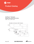
1
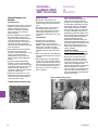
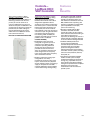
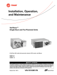
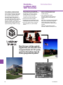
This LonMark™ certified controller
uses the Space Comfort Controller
(SCC) profile to exchange information
over a LonTalk™ network. Networks
with LonMark certified controllers
provide the latest open protocol
technology. Being LonMark certified
guarantees that owners and end-users
have the capability of adding Trane
products to other “open” systems and
relieves owners of the pressure and
expense of being locked into a single
Controls—
LonMark DDC
VAV Controller
Introduction
DDC supplier.The Trane VV550 VAV
controller with VariTrane VAV units can
be applied to more than just Trane
systems. When a customer buys a
Trane VAV unit withTrane DDC
controller, they take advantage of:
y The most educated and thorough
factory service technicians in the
controls industry
y Factory-commissioned quality
y Knowing they have selected the most
reliable VAV controllers in the industry
y Trane as a single source to solve any
VAV equipment, or system-related
issues
y Over 150 local parts centers
throughout North America that can
provide what you need, when you
need it.
Don’t let your existing controls supplier
lock you out of the most recognized
name in VAV system control in the
industry. Specify Trane open-protocol
systems.
What are the new features of this
controller? Read on to find out more.
Don’t let your existing controls
supplier lock you out of the most
recognized name in VAV system
control in the industry. Specify
Trane open-protocol systems.
C 26
VAV-PRC008-EN
Controls—
LonMark DDC
VAV Controller
Options
VV550—Trane DDC LonMark Controller
Single-Duct Terminal Unit (VCCF, VCWF, and VCEF)
Unit Heat
Cooling Only
(VCCF model)
Hot Water
(VCWF model)
Electric
(VCEF model)
Control
DD11
DD12
DD13
DD14
DD15
DD17
DD12
DD13
DD17
DD14
DD15
Description
SpaceTemp Control without Reheat
SpaceTemp Control with Remote Normally-Closed On/Off Hot Water Valve (Normally-Open Outputs)
SpaceTemp Control with Remote Proportional Hot Water Valve with Optional Spare On/Off Output
SpaceTemp Control with Remote Staged Electric Heat
SpaceTemp Control with Remote Pulse-Width Modulation Electric Heat
SpaceTemp Control with Remote Normally-Open On/Off Hot Water Valve (Normally-Closed Output)
SpaceTemp Control with Normally-Closed On/Off Hot Water Valve (Normally-Open Outputs)
SpaceTemp Control with Proportional Hot Water Valve with Optional Spare On/Off Output
SpaceTemp Control with Normally-Open On/Off Hot Water Valve (Normally-Closed Output)
SpaceTemp Control with Staged Electric Heat
SpaceTemp Control with Pulse-Width Modulation Electric Heat
Page #
C 35
C 35
C 35
C 35
C 35
C 35
C 35
C 35
C 35
C 35
C 35
Dual-Duct Terminal Unit (VDDF)
Unit Heat
Control
(VDDF model)
DD11
DD18
Description
SpaceTemp Control (No Remote Heat) and Heating Control
SpaceTemp Control (No Remote Heat) and Heating—Constant-Volume Control
Page #
C 36
C 36
Fan-Powered Terminal Units with PSC Motor (VPCF, VPWF, VPEF, VSCF, VSWF, and VSEF)
Low-Height Fan-Powered Terminal Units with PSC Motor (LPCF, LPWF, LPEF, LSCF, LSWF, and LSEF)
Unit Heat
Cooling Only
(VPCF, VSCF,
LPCF, LSCF
models)
Hot Water
(VPWF, VSWF
LPWF, LSWF)
Electric
(VPEF, VSEF
LPEF, LSEF)
Control
DD11
DD12
DD13
DD14
DD15
DD17
DD12
DD13
DD17
DD14
DD15
Description
SpaceTemp Control without Reheat
SpaceTemp Control with Remote Normally-Closed On/Off Hot Water Valve with Normally-Open Outputs
SpaceTemp Control with Remote Proportional Hot Water Valve
SpaceTemp Control with Remote Staged On/Off Electric Heat
SpaceTemp Control with Remote Pulse-Width Modulation Electric Heat
SpaceTemp Control with Remote Normally-Open On/Off Hot Water Valve with Normally-Closed Outputs
SpaceTemp Control with Normally-Closed On/Off Hot Water Valve with Normally-Open Outputs
SpaceTemp Control with Proportional Hot Water Valve
SpaceTemp Control with Normally-Open On/Off Hot Water Valve with Normally-Closed Outputs
SpaceTemp Control with Staged On/Off Electric Heat
SpaceTemp Control with Pulse-Width Modulation Electric Heat
Page #
C 37
C 37
C 37
C 37
C 37
C 37
C 37
C 37
C 37
C 37
C 37
Fan-Powered Terminal Units with ECM (VPCF, VPWF, VPEF, VSCF, VSWF, and VSEF)
Unit Heat
Cooling Only
(VPCF, VSCF
models)
Hot Water
(VPWF, VSWF
models)
Electric
(VPEF, VSEF
models)
VAV-PRC008-EN
Control
DD11
DD12
DD13
DD14
DD15
DD17
DD12
DD13
DD17
DD14
DD15
Description
SpaceTemp Control without Reheat
SpaceTemp Control with Remote Normally-Closed On/Off Hot Water Valve with Normally-Open Outputs
SpaceTemp Control with Remote Proportional Hot Water Valve
SpaceTemp Control with Remote Staged On/Off Electric Heat
SpaceTemp Control with Remote Pulse-Width Modulation Electric Heat
SpaceTemp Control with Remote Normally-Open On/Off Hot Water Valve with Normally-Closed Outputs
SpaceTemp Control with Normally-Closed On/Off Hot Water Valve with Normally-Open Outputs
SpaceTemp Control with Proportional Hot Water Valve
SpaceTemp Control with Normally-Open On/Off Hot Water Valve with Normally-Closed Outputs
SpaceTemp Control with Staged On/Off Electric Heat
SpaceTemp Control with Pulse-Width Modulation Electric Heat
Page #
C 38
C 38
C 38
C 38
C 38
C 38
C 38
C 38
C 38
C 38
C 38
C 38
C 27
Controls—
LonMark DDC
VAV Controller
General Features and
Benefits
Assured Accuracy
y Proportional-plus-integral control loop
algorithm for determining required
airflow needed to control room
temperature. Airflow is limited by
active minimum and maximum
airflow setpoints.
y Pressure-independent (PI) operation
that automatically adjusts valve
position to maintain required airflow.
In certain low-flow situations or in
cases where the flow measurement
has failed, the DDC controller will
operate in a pressure-dependent (PD)
mode of operation.
y When combined with the patented
Trane Flow ring and pressure
transducer, flow is repeatable to +/- 5%
accuracy across the Pressure
Independent (PI) flow range. (See
Valve/Controller Airflow Guidelines
section).
y Improved 2-Point Air Balancing is
available – Assures optimized flowsensing accuracy across the operating
range.This provides a more accurate
airflow balancing method when
compared to typical single-point flow
correction air balancing.
y Analog input resolution of +/- 1/8°F
within the comfort range maximizes
zone temperature control yielding
excellent comfort control.
Reliable Operation
y Built for life – Trane products are
designed to stand the test of time, with
a proven design life that exceeds 20
years.
y Fully factory tested – fully screened
and configured at the factory. All
features are tested including fan and
reheat stage energization, air valve
modulation, and controller inputs and
outputs.
Safe Operation
y All components, including the
controller, pressure transducer,
transformer, etc. are mounted in a
NEMA 1 sheet metal enclosure and are
tested as an assembly to UL1995
standards. The result is a rugged and
safe VAV, controller, and thus, overall
unit.
y When in PI-mode, EH is disabled when
the sensed flow is below the minimum
required.
y HW coil VAV units in ventilation flow
control (VFC) have a Freeze protection
algorithm to protect the water coil and
the internal space from water damage.
This is accomplished by driving the
water valve to maximum position on
alarm conditions.
Features
&
Benefits
System-Level Optimization
Trane controllers are designed to
integrate into Trane Tracer Summit
Systems and leverage clear and clean
unit-controller related data for system
level control decisions. Integrating a
Trane VV550 controller into a Tracer
Summit Control System provides the
next step in building system control.
Specifically, system-level decisions on
how to operate all components can be
made. Energy efficient optimization
strategies like Static Pressure
Optimization, Ventilation Reset, and
CO2 Demand-controlled Ventilation can
be employed with the simple press of a
button. The end-result is the most
efficient and reliable building control
system available.
Simplified Installation
Factory Commissioned Quality – All
Trane DDC VAV controllers are factorycommissioned. This means that the
DDC boards are powered and runtested with your specific sequence
parameters.They are connected to a
communication link to make sure that
information and diagnostic data
function properly. Before any VariTrane
VAV unit ships they must pass a
rigorous quality control procedure. You
can be assured that a Trane VAV unit
with Trane DDC VAV controls will work
right out of the crate.
Factory-commissioning of unit
LonMark VV550 DDC VAV Controller
C 28
VAV-PRC008-EN
Controls—
LonMark DDC
VAV Controller
Zone sensor air balance – When
applied to a Trane zone sensor with
thumbwheel and on/cancel buttons, a
balancing contractor can drive the
primary air valve to maximum or
minimum airflow from the sensor to
determine the point of calibration to be
used (maximum will result in optimum
performance). The flow reading can
then be calibrated from the sensor,
without the use of additional service
tools. (Non-LCD versions)
DDC Sensor with Thumbwheel & NSB
Tenant-Finish Heat Mode – In some
office projects, the building is being
constructed as tenants are being
identified. Tenant-finish heat mode is
designed for applications when a
given floor has not been occupied. The
main AHU system is used for heat and
because the internal furnishings are
not complete, the sensors have not
been installed. In this case, the primary
valve drives open using the heat of the
main AHU to keep plumbing lines
from freezing. When available, the
operation of the VAV unit fan (series or
parallel) remains unaffected.
Controller Flexibility
y 24 VAC binary input that can be
configured as a generic input or as
occupancy input. When the DDC
controller is operating with Tracer
Summit, the status of the input is
provided to Tracer Summit for its
action. In stand-alone operation and
when configured for an occupancy
input, the input will control occupancy
status of the DDC controller.
y Auxiliary temperature analog input
configured for an auxiliary
temperature sensor.The value of the
input is used as status-only by Tracer
Summit if Tracer Summit is providing a
supply air temperature to the DDC
controller. Otherwise, the input will be
used for determining heating/cooling
VAV-PRC008-EN
Features
&
Benefits
control action of the VAV unit. When
the auxiliary temperature sensor is
located in the discharge of the unit,
and attached to a TraneTracer Summit
BAS, additional test sequencing and
reporting is available to maximize VAV
system capabilities and simplify
system commissioning.
y Dual-duct support with two DDC
controllers. One DDC controller
controls the cooling air valve and the
other controller controls the heating air
valve. With constant-volume
sequences, the discharge air volume is
held constant by controlling discharge
air volume with the heating Controller.
y LonMark certified performance
ensures that a Trane VAV with
controller will provide state-of-the-art,
consistent open communication
protocol for integration with the
industry’s latest (Non-Trane) building
automation control systems, including
Johnson Control, Andover, Siemans,
Honeywell, etc.
y CO2 demand controlled ventilation
enables a HVAC system to adjust
ventilation flow based on critical zone,
average CO2 of specified zones, etc.
Trane demand controlled ventilation
strategies are pre-defined for simplifed
application and can be easily
customized to meet the needs of a
specific system.
C 29
Controls—
LonMark DDC
VAV Controller
Trane DDC VAV
Controller Logic
Controller
Logic
Space Temperature Control
Space temperature control
applications are where Trane emerged
as an industry leader in quality and
reliability.This did not occur overnight
and has continued to improve as our
controller and control logic has
improved over time. STC employs
controller logic designed to modulate
the supply airstream and associated
reheat (either local or remote) to
exactly match the load requirements of
the space.
Control Logic
Direct Digital Control (DDC) controllers
are today’s industry standard. DDC
controllers share system-level data to
optimize system performance
(including changing ventilation
requirements, system static pressures,
supply air temperatures, etc.). Variables
available via a simple twisted-shielded
wire pair include occupied/unoccupied
status, minimum and maximum
airflow setpoints, zone temperature
and temperature setpoints, air valve
position, airflow cfm, fan status (on or
off), fan operation mode (parallel or
series), reheat status (on or off), VAV
unit type, air valve size, temperature
correction offsets, flow correction
values, ventilation fraction, etc.
Additionally, minimum and maximum
airflow and specific controller
sequence requirements are preprogrammed to ensure that
appropriate ventilation standards are
consistently maintained. When
connected to a Trane Tracer Summit
control system, trend logging, remote
alarming, etc. are available to fully
utilize the power and capabilities of
your systems.
With the advent of LonMark open
protocol, the most reliable VAV
controller is now available for ANY
system. Gone are the days of being
locked into a single supplier.Trane DDC
controllers provide Trane-designed
solid-state electronics intended
specifically for VAV applications
including:
General Operation-Cooling
In cooling control action, the DDC
controller matches primary airflow to
cooling load. The DDC controller will
automatically change over to heating
control action if the supply air
temperature is above a configured/
editable setpoint. When the supply air
temperature is less than 10 degrees
below this setpoint, the controller will
automatically switch to cooling control
action. The DDC controller first chooses
the Tracer Summit-provided supply air
1. Space Temperature Control
2. Ventilation Flow Control (100%
outside air applications)
3. Flow Tracking Space Pressurization
Control (New feature)
Flow Sensor Signal vs. Airflow Delivery
5
Flow Sensor DP (In. wg)
1
4"
5"
6"
8"
10"
temperature value to use for auto
changeover. If this is not available, it
uses the temperature provided by the
optional auxiliary temperature sensor
(must be installed for inlet temperature
monitoring). If this is also not available,
it uses the heating/cooling mode
assigned by Tracer Summit or the DDC
controller’s service tool.
General Operation-Reheat
In heating control action, the DDC
controller matches primary airflow to
heating load. The DDC controller will
automatically change over to heating
control action if the supply air
temperature is above a configured/
editable setpoint. When the supply air
temperature is less than 10 degrees
below this setpoint, the controller will
automatically switch to cooling control
action. The DDC controller first
chooses the Tracer Summit-provided
supply air temperature value to use for
auto changeover. If this is not available,
it uses the temperature provided by
the optional auxiliary temperature
sensor (must be installed for inlet
temperature monitoring). If this is also
not available, it uses the heating/
cooling mode assigned by Tracer
Summit or the DDC controller’s service
tool.
When heat is added to the primary air,
the air is considered reheated. Reheat
can be either local (integral to the VAV
unit in the form of an electric coil or hot
water coil) or remote (typically
existing wall fin radiation, convector,
etc.) or any combination of local and
remote. The operating characteristics of
the four basic types of VariTrane DDC
terminal reheat are discussed.
12" 14" 16"
0.1
0.01
10
100
1,000
10,000
Cfm
Note: Flow sensor DP (in. wg) is measured at the flow ring to aid in system balancing and commissioning. See
"Valve/Controller Airflow Guidelines" in each section for unit performance.
C 30
VAV-PRC008-EN
Controls—
LonMark DDC
VAV Controller
Single-Duct: On/Off Hot Water Reheat –
Three stages of on/off hot water reheat
are available. Two-position water valves
complete the HW reheat system and are
either fully opened or fully closed. The
heating minimum airflow setpoint is
enforced during reheat.
Stage 1 energizes when the space
temperature is at or below the heating
setpoint. When the zone temperature
rises above the active heating setpoint
by 0.5°F (0.28°C), stage 1 is de-energized.
Stage 2 energizes when the space
temperature is 1°F (0.56°C) or more
below the active heating setpoint, and is
de-energized when the space
temperature is 0.5°F (0.28°C) below the
active heating setpoint. Stage 3
energizes when the zone temperature is
2°F (1.11°C) or more below the active
heating setpoint, and de-energizes when
the space temperature is 1.5°F (0.83°C)
below the active heating setpoint. When
reheat is de-energized, the cooling
minimum airflow setpoint is activated.
Single-Duct: Proportional Hot
Water Reheat –
Proportional hot water reheat uses 3wire floating-point-actuator technology.
The heating minimum airflow setpoint is
enforced during reheat.
The water valve opens as space
temperature drops below the heating
setpoint. A separate reheat proportionalplus-integral control loop from that
controlling airflow into the room is
enforced. Water valve position is
dependent on the degree that the space
temperature is below the active heating
setpoint and the time that the space
temperature has been below the active
VCEF
VAV-PRC008-EN
heating setpoint. If not already closed,
the water valve fully closes when the
zone temperature rises above the
active heating setpoint by 0.5 °F (0.28
°C). An additional on/off remote heat
output is available and energized when
the proportional valve is driven 100%
open and de-energized when the
proportional valve reaches 50% open.
When reheat is de-energized, the
cooling minimum airflow setpoint is
activated. Again, these reheat devices
can be either local or remote.
Single-Duct: On/Off Electric Reheat –
One, two, or three stages of staged
electric reheat are available. The
heating minimum airflow setpoint is
enforced during reheat.
Stage 1 is energized when the space
temperature falls below the active
heating setpoint and minimum airflow
requirements are met. When the zone
temperature rises above the active
heating setpoint by 0.5°F (0.28°C),
stage 1 is de-energized. Stage 2
energizes when the space temperature
is 1°F (0.56°C) or more below the active
heating setpoint, and is de-energized
when the space temperature is 0.5°F
(0.28°C) below the active heating
setpoint. Stage 3 energizes when the
zone temperature is 2°F (1.11°C) or
more below the active heating
setpoint, and de-energizes when the
space temperature is 1.5°F (0.83°C)
below the active heating setpoint.
When reheat is de-energized, the
cooling minimum airflow setpoint is
activated.
Controller
Logic
Single-Duct: Pulse-Width Modulation
of Electric Heat –
One to three stages of pulse-width
modulation of electric heat are
available. Energizing for a portion of a
three-minute time period modulates
the electric heater.This allows exact
load matching for energy efficient
operation, and optimum zone
temperature control. The heating
minimum airflow setpoint is enforced
during reheat.
The amount of reheat supplied is
dependent on both the degree that the
space temperature is below the active
heating setpoint and the time that the
space temperature has been below the
active heating setpoint. If not already
off, reheat de-energizes when the zone
temperature rises more than 0.5°F
(0.28°C) above the heating setpoint.
The Stage 1 “on” time is proportional
to the amount of reheat required. For
example, when 50% of stage 1
capacity is required, reheat is on for 90
seconds and off for 90 seconds. When
75% of stage 1 capacity is required,
reheat is on for 135 seconds and off for
45 seconds. When 100% of stage 1
capacity is required, reheat is on
continuously.
Stage 2 uses the same “on” time logic
as stage 1 listed above, except stage 1
is always energized. For example,
when 75% of unit capacity is required,
stage 1 is energized continuously, and
stage 2 is on for 90 seconds and off for
90 seconds. When reheat is deenergized, the cooling minimum
airflow setpoint is activated. Caution:
Care should be taken when sizing
electric heaters. Leaving air
temperatures (LAT) should not exceed
100°–110°F, with 95°F being the optimal
for zone temperature and comfort
control. At elevated LATs, room
stratification may result in uneven air
distribution and zone temperature
complaints. To prevent stratification,
the warm air temperature should not
be more than 20°F (6.7°C) above zone
air temperature. (See Diffuser, “D”,
section for additional application
details)
C 31
Controls—
LonMark DDC
VAV Controller
Fan-Powered Terminal Units:
On/Off Hot Water Reheat –
One or two stages of on/off hot water
reheat are available. Two position
water valves complete the HW reheat
system and are either fully opened or
fully closed. The heating minimum
airflow setpoint is enforced during
reheat.
On parallel fan-powered units, the fan
is energized upon a call for heating. The
parallel fan is turned off when the
space temperature rises above the fan
on/off point (active heating setpoint
plus fan offset) plus 0.5°F (0.28°C).
Series fan-powered terminal unit fans
are continuously energized during
occupied mode. When unoccupied, the
fan is energized upon a call for heating
or cooling and de-energized when
unoccupied zone set point is satisfied.
When the zone temperature falls below
the active heating setpoint, the UCM
modulates the primary airflow to the
minimum heating airflow setpoint.
Stage 1 energizes when the space
temperature is below the active
heating setpoint, and is de-energized
when the space temperature is 0.5°F
(0.28°C) above the active heating
setpoint. Stage 2 energizes when the
zone temperature is 1°F (0.56°C) or
more below the active heating
setpoint, and de-energizes when the
space temperature is 0.5°F (0.28°C)
below the active heating setpoint.
When reheat is de-energized, the
cooling minimum airflow setpoint is
activated.
Fan-Powered Terminal Units:
Proportional Hot Water Reheat –
Proportional hot water reheat uses
3-wire floating-point-actuator
technology.The heating minimum
airflow setpoint is enforced during
reheat.
On parallel fan-powered units, the fan
is energized upon a call for heating. The
parallel fan is turned off when the
space temperature rises above the fan
on/off point (active heating setpoint
plus fan offset) plus 0.5ºF (0.28ºC).
Series fan-powered terminal unit fans
are continuously energized during
occupied mode. When unoccupied, the
fan is energized upon a call for heating
or cooling and de-energized when
unoccupied zone setpoint is satisfied.
The water valve opens as space
temperature drops below the heating
setpoint. A separate reheat
C 32
Controller
Logic
VPEF
VSEF
proportional-plus-integral control loop
from that controlling airflow into the
room is enforced. The degree to which
the hot water valve opens is
dependent on both the degree that the
space temperature is below the active
heating setpoint and the time that the
space temperature has been below the
active heating setpoint. If not already
closed, the water valve fully closes
when the zone temperature rises
above the active heating setpoint by
0.5 °F (0.28 °C). When reheat is deenergized, the cooling minimum
airflow setpoint is activated.
Fan-powered Terminal Units:
On/Off Electric Reheat –
One or two stages of staged electric
reheat are available. The heating
minimum airflow setpoint is enforced
during reheat.
On parallel fan-powered units, the fan
is energized upon a call for heating. The
parallel fan is turned off when the
space temperature rises above the fan
on/off point (active heating setpoint
plus fan offset) plus 0.5°F (0.28°C).
Series fan-powered terminal unit fans
are continuously energized during
occupied mode. When unoccupied, the
fan is energized upon a call for heating
or cooling and de-energized when
unoccupied zone set point is satisfied.
Stage 1 energizes when the space
temperature is below the active
heating setpoint, and is de-energized
when the space temperature rises
0.5°F (0.28°C) above the active heating
setpoint. Stage 2 energizes when the
space temperature is 1.0°F (0.56°C) or
more below the active heating
setpoint, and is de-energized when the
space temperature is 0.5°F (0.28°C)
below the active heating setpoint.
When reheat is de-energized, the
cooling minimum airflow setpoint is
activated.
Fan-powered Terminal Units:
Pulse-Width Modulation of Electric
Heat –
One or two stages of pulse-width
modulation of electric heat are
available. Energizing for a portion of a
three-minute time period modulates
the electric heater.This allows exact
load matching for energy efficient
operation and optimum zone
temperature control. The heating
minimum airflow setpoint is enforced
during reheat.
On parallel fan-powered units, the fan
is energized upon a call for heating. The
parallel fan is turned off when the
space temperature rises above the fan
on/off point (active heating setpoint
plus fan offset) plus 0.5°F (0.28°C).
Series fan-powered terminal unit fans
are continuously energized during
occupied mode. When unoccupied, fan
is energized upon a call for heating or
cooling and de-energized when
unoccupied zone set point is satisfied.
The amount of reheat supplied is
dependent on both the degree that the
space temperature is below the active
heating setpoint and the time that the
space temperature has been below the
active heating setpoint. If not already
off, reheat de-energizes when the
space temperature rises 0.5°F (0.28°C)
above the active heating setpoint. The
Stage 1 “on” time is proportional to the
amount of reheat required. For
example, when 50% of stage 1
capacity is required, reheat is on for 90
seconds and off for 90 seconds. When
75% of stage 1 capacity is required,
reheat is on for 135 seconds and off for
45 seconds. When 100% of stage 1
capacity is required, reheat is on
continuously.
Stage 2 uses the same “on” time logic
as stage 1 listed above, except stage 1
is always energized. For example,
when 75% of unit capacity is required,
stage 1 is energized continuously, and
stage 2 is on for 90 seconds and off for
90 seconds. When reheat is deenergized, the cooling minimum
airflow setpoint is activated. When
reheat is de-energized, the cooling
minimum airflow setpoint it activated.
VAV-PRC008-EN
Controls—
LonMark DDC
VAV Controller
Ventilation Control
Ventilation control enhances the
usability of Trane DDC controllers in
more select applications that require
measurement of outside air
(ventilation). Ventilation control is
designed for use with constant volume
single-duct VAV units which modulate
VAV-PRC008-EN
the primary damper and associated
reheat to maintain an average constant
discharge air temperature. The reheat
is modulated to provide discharge air
temperature consistent with AHU
supply air temperature (typically 50º–
60ºF). This is critical to ensure that
ASHRAE Standard 62 Ventilation
Ventilation
Control
standards are attained, consistently
maintained, and monitored. When
connected to a Trane Summit control
system, trend logging, remote
alarming, etc. is available. In fact, the
Trane Tracer Control System can
provide unmatched “peace of mind”
by calling/paging the appropriate
person(s) when specific alarms occur.
C 33
Controls—
LonMark DDC
VAV Controller
the air valve to maintain space
comfort, the exhaust box modulates a
similar amount to maintain the
required CFM differential. This is a
simple, reliable means of
pressurization control, which meets the
requirements of the majority of zone
pressurization control applications.
Typical applications include:
Flow Tracking Control
This enhanced VAV DDC controller
feature allows two Trane VV550
controllers to coordinate modulation
simultaneously. This allows a specific
CFM offset to be maintained.The CFM
offset provides pressurization control
of an occupied space, while
maintaining the comfort and energy
savings of a VAV system. A flow
tracking system in a given zone
consists of a standard Space Comfort
Control VAV (see B )unit plus a singleduct, cooling-only, exhaust VAV unit
(see C ). As the supply VAV unit
modulates the supply airflow through
y School and University laboratories
Flow
Tracking
The CFM offset is assured and can be
monitored and documented when
connected to a Trane Tracer Summit
Building Automation System. Flow
Tracking Control is designed to meet
most pressurization control projects. If
an application calls for pressure control
other than flow tracking, contact your
local Trane Sales Office for technical
support.
y Industrial laboratories
y Hospital operating rooms
y Hospital patient rooms
y Research and Development facilities
y And many more…
How Does It Operate?
Supply VAV
Exhaust
To other VAVs or
Main Control Panel
B
Primary Air
from Main
AHU
Communication link
A
C
T
Occupied Space
C 34
VAV-PRC008-EN
Controls—
LonMark DDC
VAV Controller
Control
Drawings
VV550—DDC LonMark Controller for Single-Duct Terminals
DD11–Space Temp Control Cooling Only
DD12–Space Temp Control w/ N.C. Hot Water Valve
DD13–Space Temp Control w/ Modulating Hot Water Valve
DD14 Space Temp Control w/ Stage Electric Heat
DD15–Space Temp Control w/ Pulse-width Modulation
DD17–Space Temp Control w/ N.O. Hot Water Valve
HEATER STAGE
OPTIONAL
CONTACTOR(S)
TRANSFORMER
10.
7.
2ND
TO
DAMPER
ACTUATOR
3RD
24VAC 60HZ
NEC CLASS - 2
CONTROL CIRCUIT
LOAD = 8 VA
(WITHOUT HEAT)
6.
Y or (W)
SCREW
8.
OPTIONAL
DISCONNECT
SWITCH
BK
10.
OPTIONAL POWER
J8
TB1-1
GREEN
BL or (BK)
G-OPEN
OPTIONAL
FUSE, DISCONNECT
& TRANSFORMER
R-CLOSE
WH-HOT
BL
Y
WH-HOT
BL
Y
R
O
BR
BL
Y
1ST
V
8.
BL
(50VA)
OPTIONAL
FUSE
Y
TB1-1
TB1-2
9.
GND 24V
VV550
5.
R (HOT)
(TB4-2) 24VAC
O (COMMON)
(TB4-1) BIP
(TB4-2) 24VAC
Tracer VV550
BK (RETURN)
(TB1-2) GND
Y
NOT CONNECTED
OPTIONAL FIELD INSTALLED
OCCUPANCY SENSOR
PRESSURE
TRANSDUCER
R
G
TB2-6
TB3-1
TB2-5
TB3-2
TB3-3
+
VOUT
TB2-2
-
5
4
3
2
1
ZONE SENSOR
W/ COMM. JACK
REMOTE MTD.
3.
VV550
CONTROL BOX
4.
OPTIONAL FIELD
INSTALLED ZONE SENSOR
TWISTED PAIR
COMMUNICATIONS
WIRING
NOTES:
1.
TB3-5
TB3-6
BK (CLOSE)
TO J9
R (OPEN)
TO J10
Factory Wiring
Field Wiring
Optional or Alternate Wiring
OPTIONAL FIELD INSTALLED
AUX TEMP SENSOR
2.
1/4" Quick connect required for all field connections.
3.
Zone sensor terminals 4 and 5 required twisted pair wiring for communications jack equipped zone sensor option.
4.
No additional wiring required for night setback override (ON/CANCEL).
5.
The optional binary input connects between TB4–1 (BIP) and 24VAC (HOT) from transformer. The binary input
can be reconfigured as an occupancy input via the communications interface.
6.
If unit mounted transformer is not provided, polarity from unit to unit must be maintained to prevent permanent
damage to control board. If one leg of 24VAC supply is grounded, then ground leg must be connected to TB1–2.
7.
Contactors are 24 VAC: 12VA max/coil (Mercury contactors). 10VA max/coil (Magnetic contactors).
8.
Optional fuse, disconnect switch and transformer wiring (cooling only or hot water units). Wiring goes through
9.
Transformer wire colors: 120V–
–
W (HOT)
TO J8
FIELD INSTALLED
PROP.
WATER
VALVE
24VAC
12VA MAX
OPTIONAL FIELD INSTALLED
PROPORTIONAL WATER VALVE
TO J9
TO J8
ON - OFF
WATER VALVE
24 VAC
12VA MAX
OPTIONAL FIELD INSTALLED
0N-OFF WATER VALVE
–O, 277V–BR, 480V–R/BK, 575V–R, 190V–R, 220V–R, 347V–R.
10.
11. Three-stage not available with pulse-width modulation.
VAV-PRC008-EN
C 35
Controls—
LonMark DDC
VAV Controller
Control
Drawings
VV550—DDC LonMark Controller for Dual-Duct Terminals
DD11–Space Temp Control (No Remote Heat) and Heating Control
DD18–Space Temp Control (No Remote Heat) and Heating Control—Constant-Volume Control
COOLING VALVE
24VAC
TO TB1 ON
HEATING
VALVE UCM
6.
DAMPER
ACTUATOR
WIRING
24VAC 50/60 HZ
NEC CLASS-2
CONTROL CIRCUIT
LOAD = 16VA
Y
GROUND
SCREW
CLOSE
HOT
HOT
Y
2
OPTIONAL
DISCONNECT
BL
1
OPEN
TB4
or (BK)
OPTIONAL
FUSE, DISCONNECT
& TRANSFORMER
BL
OPTIONAL POWER
TRANSFORMER
(50VA)
BL
TB4
Tracer VV550
TB3-5
PRESSURE
TRANSDUCER
OPTIONAL
FUSE
Y
1
2
TB3-6
OPTIONAL FIELD INSTALLED
AUX TEMP SENSOR
+
R
VOUT
G
5.
R ((HOT))
(TB4-2) 24VAC
(TB4-1) BIP
VV550
CONTROL BOX
(TB4-2) 24VAC
Y
TWISTED PAIR
COMMUNICATIONS
WIRING
FIELD INSTALLED
NOT CONNECTED
OCCUPANCY SENSOR
TB2-6
TB3-1
TB2-5
TB3-2
TB3-3
HEATING VALVE
24VAC
TO TB4 IN
COOLING
5
DAMPER
ACTUATOR
WIRING
4
3
2
1
4.
OPTIONAL FIELD
INSTALLED ZONE SENSOR
Y
CLOSE
HOT
HOT
Y
BL
OPEN
BL
NOTE:
1.
Factory Wiring
Field Wiring
Optional or Alternate Wiring
2. 1/4" quick connect required for all field connections.
3. Zone sensor terminals 4 and 5 require twisted pair wiring for communications
jack equipped zone sensor option.
4. No additional wiring required for night setback override (ON/CANCEL).
Tracer VV550
5. The optional binary input connects between TB4-1 (BIP) and 24VAC (HOT) from transformer. The binary
input can be reconfigured as an occupancy input via the communications interface.
6. If unit mounted transformer is not provided, polarity from unit to unit must be maintained to prevent permanent
damage to control board. If one leg of 24VAC supply is grounded, then ground leg must be connected to TB1-2.
PRESSURE
TRANSDUCER
7. Optional fuse, disconnect switch and transformer wiring.
8. Cooling controller space temperature and space setpoint network variables should be bound heating controller.
R
BK
G
+
VOUT
-
VV550
CONTROL BOX
TWISTED PAIR
COMMUNICATIONS
WIRING
FIELD INSTALLED
C 36
VAV-PRC008-EN
Controls—
LonMark DDC
VAV Controller
Control
Drawings
VV550—DDC LonMark Controller for Fan-Powered Terminals
DD11–Space Temp Control Cooling Only
DD12–Space Temp Control w/ N.C. Hot Water Valve
DD13–Space Temp Control w/ Modulating Hot Water Valve
DD14–Space Temp Control w/ Stage Electric Heat
DD15–Space Temp Control w/ Pulse-width Modulation
DD17–Space Temp Control w/ N.O. Hot Water Valve
6.
OPTIONAL FIELD INSTALLED
ELECTRIC HEATER
8.
7.
HEATER STAGE
2ND
V
5.
TO
DAMPER
ACTUATOR
R (HOT)
TO FAN RELAY
BK (RETURN)
(TB4-2) 24VAC
(TB1-2) GND
NOT CONNECTED
OPTIONAL FIELD INSTALLED
OCCUPANCY SENSOR
TB2-6
TB3-1
TB2-5
TB3-2
TB3-3
BR
R (FAN)
BL
5
4
3
2
1
G-OPEN
ZONE SENSOR
R-CLOSE
WH-HOT
WH-HOT
V
(TB4-1) BIP
GR (NC CONTACT)
Y
R (FAN)
BR
O
BR
BL
Y
(TB4-2) 24VAC
O (COMMON)
Y
1ST
O
BR
CONTACTOR(S)
TO TRANSFORMER
REMOTE MTD.
4.
OPTIONAL FIELD
INSTALLED ZONE SENSOR
TB3-5
TB3-6
OPTIONAL FIELD INSTALLED
AUX TEMP SENSOR
W (HOT)
TO J8
BK (CLOSE)
Tracer VV550
TO J9
TO J10
R (OPEN)
PROP.
WATER
VALVE
24VAC
12VA MAX
PROPORTIONAL WATER VALVE
PRESSURE
TRANSDUCER
R
BK
G
+
VOUT
-
TO J9
TO J8
ON - OFF
WATER VALVE
24 VAC
12VA MAX
OPTIONAL FIELD INSTALLED
0N-OFF WATER VALVE
VV550
CONTROL BOX
TWISTED PAIR
COMMUNICATIONS
WIRING
FIELD INSTALLED
NOTES:
1.
2.
Factory Wiring
Field Wiring
Optional or Alternate Wiring
1/4" Quick connect required for all field connections.
3.
4.
No additional wiring required for night setback override (ON/CANCEL).
5.
The optional binary input connects between TB4–1 (BIP) and 24VAC (HOT from transformer. The binary input can be
Transformer provided in all units.
8.
VAV-PRC008-EN
Contactors are 24 VAC: 12 VA max/coil (Mercury contactors). 10VA max/coil (Magnetic contactors).
C 37
Controls—
LonMark DDC
VAV Controller
Control
Drawings
VV550—DDC LonMark Controller for ECM Fan-Powered Terminals
DD11—Space Temp Control Cooling Only
DD12—Space Temp Control w/ N.C. Hot Water Valve
DD13—Space Temp Control w/ Modulating Hot Water Valve
DD14—Space Temp Control w/ Stage Electric Heat
DD15—Space Temp Control w/ Pulse-width Modulation
DD17—Space Temp Control w/ N.O. Hot Water Valve
TO
DAMPER
ACTUATOR
HEATER STAGE
CONTACTOR(S)
7.
OPTIONAL OR FIELD INSTALLED
ELECTRIC HEATER
TO TRANSFORMER
2ND
Y
BL
Y
BL
G-OPEN
R-CLOSE
WH-HOT
WH-HOT
V
O
1ST
BR
TO
ECM
MOTOR
8.
Y
BK
R
NEUT.
2
24V
RED
BL
RED
4
BL
Tracer VV550
24V
3
OPTIONAL FIELD INSTALLED
AUX TEMP SENSOR
6.
R
1
TB3-6
ECM
BOARD
G
R
BK
TB3-5
W
BK
BL
Y
BL
TB2-6
TB3-1
TB2-5
MOTOR
RELAY
5
TB4-2
PRESSURE
TRANSDUCER
R
BK
G
TB3-2
TB3-3
4
3
2
1
ZONE SENSOR
W/ COMM. JACK
REMOTE MTD.
+
3.
4.
VOUT
-
OPTIONAL FIELD
INSTALLED ZONE SENSOR
VV550
CONTROL BOX
5.
TWISTED PAIR
COMMUNICATIONS
WIRING
FIELD INSTALLED
R (HOT)
(TB4-2) 24VAC
O (COMMON)
(TB4-1) BIP
GR (NC CONTACT)
BK (RETURN)
Y
(TB4-2) 24VAC
(TB1-2) GND
NOT CONNECTED
OPTIONAL FIELD INSTALLED
OCCUPANCY SENSOR
W (HOT)
TO J8
BK (CLOSE)
TO J9
TO J10
R (OPEN)
PROP.
WATER
VALVE
24VAC
12VA MAX
OPTIONAL FIELD INSTALLED
PROPORTIONAL WATER VALVE
ON - OFF
WATER VALVE
24 VAC
12VA MAX
TO J9
TO J8
OPTIONAL FIELD INSTALLED
0N-OFF WATER VALVE
NOTES:
1.
Factory Wiring
Field Wiring
Optional or Alternate Wiring
2.
1/4" Quick connect required for all field connections.
3.
Zone sensor terminals 4 and 5 require twisted pair wiring for communcations jack equipped zone sensor option.
4.
No additional wiring required for night setback override (ON/CANCEL).
5.
The optional binary input connects between TB4–1 (BIP) and 24VAC (HOT) from transformer. Input can be
reconfigured as an occupancy input via the communications interface.
6.
Fan CFM can be easily adjusted from its min CFM to its max CFM via the ECM control board dial switches with
a flat-head screwdriver. The switches set the percentage flow.
Contactors are 24 VAC: 12VA max/coil (Mercury contactors). 10VA max/coil (Magnetic contactors).
9.
C 38
Three-stage not available with pulse-width modulation.
VAV-PRC008-EN
Controls—
LonMark DDC
VAV Controller
Accessories
LonMark Direct Digital
Controller—Unit Control
Module
The Trane LonMark direct digital
controller Unit Control Module (DDCUCM) is a microprocessor-based
terminal unit with non-volatile memory
which provides accurate airflow and
room temperature control of Trane and
non-Trane VAV air terminal units.
LonMark provides a simple open
protocol to allow integration of Trane
VAV units and controls into other
existing control systems. The UCM can
operate in pressure-independent or
pressure-dependent mode and uses a
proportional plus integral control
algorithm. The controller monitors
zone temperature setpoints, zone
temperature and its rate of change and
valve airflow (via flow ring differential
pressure). The controller also accepts
an auxiliary duct temperature sensor
input or a supply air temperature value
from Tracer Summit. Staged electric
heat, pulse width modulated electric
heat, proportional hot water heat or on/
off hot water heat control are provided
when required. The control board
operates using
24-VAC power. TheTrane LonMark
DDC-UCM is also a member of the
Trane Integrated Comfort™ systems
(ICS) family of products. When used
with a Trane Tracer Summit™ building
management controller or other Trane
controllers, zone grouping and unit
diagnostic information can be
obtained. Also part of ICS is the factorycommissioning of parameters
specified by the engineer (see "FactoryInstalled vs. Factory-Commissioned" in
the Features and Benefits section for
more details).
SPECIFICATIONS
Supply voltage:
24 VAC, 50/60 Hz
Maximum VA load:
No heat or fan:
8 VA (Board, Transducer, Zone Sensor,
and Actuator)
Physical dimensions:
Width:
5.5" (139.7 mm)
Length:
4.5" (69.85 mm)
Height:
2.0" (44.45 mm)
Connections:
1/4" (6.35 mm) Stab Connections
Note: If using field-installed heat,
24 VAC transformer should be sized
for additional load.
Communications:
LonMark – Space Comfort Control
(SCC) profile with FTT-10 transceiver.
Output ratings:
Actuator Output:
1st Stage Reheat:
2nd Stage Reheat:
3rd Stage Reheat:
22 awg. unshielded level 4
communication wire.
24 VAC at 12 VA
24 VAC at 12 VA
24 VAC at 12 VA
24 VAC at 12 VA
Binary input:
24 VAC, occupancy or generic.
Auxiliary input:
Can be configured for discharge or
primary air temperature sensor.
Operating environment:
32 to 140°F, (0 to 60°C)
5% to 95% RH, Non-condensing
Storage environment:
-40 to 180°F (-40 to 82.2°C),
5% to 95%RH, Non-Condensing
Fan control:
Series fan: On unless unoccupied
and min. flow has been
released.
Parallel fan: On when zone
temperature is less than
heating setpoint plus fan
offset. Off when zone
temperature is more than
heating setpoint plus fan
offset plus 0.5°F (0.28°C).
Heat staging:
Staged electric or hot water
proportional or pulse-width
modulation
For additional accessory information, refer to pages C 17 – 25.
Note:Trane LonMark DDC-UCM
controllres can also take advancage of
factory-commissioned quality on nonTrane systems through LonMark open
protocol.
VAV-PRC008-EN
C 39
Controls—
LonMark DDC
VAV Controller
Data Lists
Table 1 provides an input/output listing forTracer VV550/551 VAV controllers. Table 2 provides the configuration properties for the
controller.The content of the lists conforms to both the LonMark SCC functional profile 8500 and the LonMark node object.
Table 1. Input/output listing
Input description
Space temperature
Setpoint
Occupancy, schedule
Occupancy, manual command
Occupancy sensor
Application mode
Heat/cool mode input
Fan speed command
Auxiliary heat enable
Valve override
Flow override
Emergency override
Source temperature
Space CO2
Clear alarms/diagnostics
Air flow setpoint input
* Part of the node object.
Input
SNVT type
Output description
Output
SNVT type
nviSpaceTemp
nviSetpoint
nviOccSchedule
nviOccManCmd
nviOccSensor
nviApplicMode
nviHeatCool
nviFanSpeedCmd
nviAuxHeatEnable
nviValveOverride
nviFlowOverride
nviEmergOverride
nviSourceTemp
nviSpaceCO2
nviRequest*
nviAirFlowSetpt
SNVT_temp_p
SNVT_temp_p
SNVT_tod_event
SNVT_occupancy
SNVT_occupancy
SNVT_hvac_mode
SNVT_hvac_mode
SNVT_switch
SNVT_switch
SNVT_hvac_overid
SNVT_hvac_overid
SNVT_hvac_emerg
SNVT_temp_p
SNVT_ppm
SNVT_obj_request
SNVT_flow
Space temperature
Unit status, mode
Effective setpoint
Effective occupancy
Heat cool mode
Setpoint
Discharge air temperature
Space CO2
Effective air flow setpoint
Air flow
File table address
Object status
Alarm message
*Part of the node object.
nvoSpaceTemp
nvoUnitStatus
nvoEffectSetpt
nvoEffectOccup
nvoHeatCool
nvoSetpoint
nvoDischAirTemp
nvoSpaceCO2
nvoEffectFlowSP
nvoAirFlow
nvoFileDirectory*
nvoStatus*
nvoAlarmMessage
SNVT_temp_p
SNVT_hvac_status
SNVT_temp_p
SNVT_occupancy
SNVT_hvac_mode
SNVT_temp_p
SNVT_temp_p
SNVT_ppm
SNVT_flow
SNVT_flow
SNVT_address
SNVT_obj_status
SNVT_str_asc
Table 2. Configuration properties
Configuration property description
Send heartbeat
Occ temperature setpoints
Minimum send time
Receive heartbeat
Location label
Local bypass time
Manual override time
Space CO2 limit
Nominal air flow
Air flow measurement gain
Minimum air flow
Maximum air flow
Minimum air flow for heat
Maximum air flow for heat
Minimum flow for standby
Firmware major version
Firmware minor version
Flow offset for tracking applications
Local heating minimum air flow
Minimum flow for standby heat
* Part of the node object.
C 40
Configuration property
SNVT type
SCPT reference
nciSndHrtBt
nciSetpoints
nciMinOutTm
nciRecHrtBt
nciLocation
nciBypassTime
nciManualTime
nciSpaceCO2Lim
nciNomFlow
nciFlowGain
nciMinFlow
nciMaxFlow
nciMinFlowHeat
nciMaxFlowHeat
nciMinFlowStdby
nciDevMajVer*
nciDevMinVer*
nciFlowOffset
nciMinFlowUnitHt
nciMnFlowStbyHt
SNVT_time_sec
SNVT_temp_setpt
SNVT_time_sec
SNVT_time_sec
SNVT_str_asc
SNVT_time_min
SNVT_time_min
SNVT_ppm
SNVT_flow
SNVT_multiplier
SNVT_flow
SNVT_flow
SNVT_flow
SNVT_flow
SNVT_flow
n/a
n/a
SNVT_flow_f
SNVT_flow
SVNT_flow
SCPTmaxSendTime (49)
SCPTsetPnts (60)
SCPTminSendTime (52)
SCPTmaxRcvTime (48)
SCPTlocation (17)
SCPTbypassTime (34)
SCPTmanOverTime (35)
SCPTlimitCO2 (42)
SCPTnomAirFlow (57)
SCPTsensConstVAV (67)
SCPTminFlow (54)
SCPTmaxFlow (51)
SCPTminFlowHeat (55)
SCPTmaxFlowHeat (37)
SCPTminFlowStby (56)
SCPTdevMajVer (165)
SCPTdevMinVer (166)
SCPToffsetFlow (265)
SCPTminFlowUnitHeat (270)
SCPTminFlowStbyHeat(263)
VAV-PRC008-EN