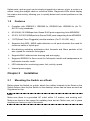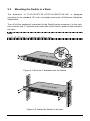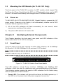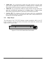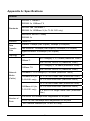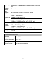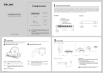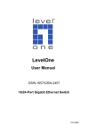
1
User Guide
TL-SL1210
8-Port 10/100Mbps + 2-Port Gigabit Switch
TL-SL1117
16-Port 10/100Mbps + 1-Port Gigabit Switch
TL-SL1226
24-Port 10/100Mbps + 2-Port Gigabit Switch
TL-SL1351
48-Port 10/100Mbps + 3-Port Gigabit Switch
Rev: 2.0.0
7106503252
COPYRIGHT & TRADEMARKS
Specifications are subject to change without notice.
is a
registered trademark of TP-LINK TECHNOLOGIES CO., LTD. Other brands and
product names are trademarks or registered trademarks of their respective holders.
No part of the specifications may be reproduced in any form or by any means or
used to make any derivative such as translation, transformation, or adaptation
without permission from TP-LINK TECHNOLOGIES CO., LTD. Copyright © 2010
TP-LINK TECHNOLOGIES CO., LTD. All rights reserved.
http://www.tp-link.com
FCC STATEMENT
This equipment has been tested and found to comply with the limits for a Class A
digital device, pursuant to part 15 of the FCC Rules. These limits are designed to
provide reasonable protection against harmful interference when the equipment is
operated in a commercial environment. This equipment generates, uses, and can
radiate radio frequency energy and, if not installed and used in accordance with
the instruction manual, may cause harmful interference to radio communications.
Operation of this equipment in a residential area is likely to cause harmful
interference in which case the user will be required to correct the interference at
his own expense.
This device complies with part 15 of the FCC Rules. Operation is subject to the
following two conditions:
1)
This device may not cause harmful interference.
2) This device must accept any interference received, including interference that
may cause undesired operation.
Any changes or modifications not expressly approved by the party responsible for
compliance could void the user’s authority to operate the equipment.
EC DECLARATION OF CONFORMITY (EUROPE)
In compliance with the EMC Directive 89/336/EEC, Low Voltage Directive 73/23/
EEC, this product meets the requirements of the following standards:
¾
EN55022
¾
EN55024
¾
EN60950
CE MARK WARNING
This is a class A product. In a domestic environment, this product may cause radio
interference, in which case the user may be required to take adequate measures.
SAFETY NOTICES
Cautions:
Do not use this product near water, for example, in a wet basement or near a
swimming pool.
Avoid using this product during an electrical storm. There may be a remote risk of
electric shock from lightning.
CONTENTS
Package Contents:.............................................................................1
Chapter 1
Introduction of the Product .........................................1
1.1
Overview of the product .................................................................... 1
1.2
Features ............................................................................................ 2
Chapter 2
Installation.....................................................................2
2.1
Mounting the Switch on a Desk ......................................................... 2
2.2
Mounting the Switch in a Rack .......................................................... 3
2.3
Mounting the SFP Module (for TL-SL1351 Only) .............................. 4
2.4
Power on ........................................................................................... 4
Chapter 3
Identifying External Components................................4
3.1
Front Panel........................................................................................ 4
3.2
Rear Panel ........................................................................................ 5
Appendix A: Specifications ...............................................................6
Package Contents
The following items should be found in your box:
¾
One Switch
¾
One power cord
¾
This User's Guide
¾
Rubber footpads for Desk-mount
¾
Rack-mount kit for installing the switch in a 19-inch rack
Note:
Make sure that the package contains the above items. If any of the listed items are
damaged or missing, please contact with your distributor.
Chapter 1
Introduction of the Product
This chapter describes the features of the TL-SL1210 / TL-SL1117 / TL-SL1226 /
TL-SL1351 Gigabit Switch. TL-SL1210, TL-SL1117, TL-SL1226 and TL-SL1351
just differ in the number of LED indicators and ports, and all figures in this user
guide are of TL-SL1351.
1.1
Overview of the product
The TL-SL1210/TL-SL1117/TL-SL1226/TL-SL1351 Gigabit Switch provides you
with a high-performance, low-cost, easy-to-use, seamless and standard upgrade
to boost your old network to 1000Mbps. Increase the speed of your network server
and backbone connections, make Gigabit connection to a server or uplink a
network necessarily.
The TP-LINK TL-SL1210/TL-SL1117/TL-SL1226/TL-SL1351 features a nonblocking switching architecture that forwards and filters packets at full wire-speed
for maximum throughput. MAC address auto-learning and auto-aging, IEEE802.3x
flow control for Full Duplex mode and backpressure for Half Duplex mode. It is
compatible with all 10,100, and 1000Mbps Ethernet devices because it is
standard-based.
The TL-SL1210/TL-SL1117/TL-SL1226/TL-SL1351 is plug-and-play and no
configuration is required. Auto MDI/MDIX cable detection on all ports eliminate the
need for crossover cable or Uplink port. Each port can be used as general ports or
1
Uplink ports, and any port can be simply plugged into a server, a hub, a router or a
switch, using the straight cable or crossover cable. Diagnostic LEDs which display
link status and activity, allowing you to quickly detect and correct problems on the
network.
1.2
Features
¾
Complies with IEEE802.3, IEEE802.3u, IEEE802.3ab, IEEE802.3z (for TLSL1351 only) standards
¾
8/16/24/48 10/100Mbps Auto-Sense RJ45 ports supporting Auto-MDI/MDIX
¾
2/1/2/2 10/100/1000Mbps Auto-Sense RJ45 ports supporting Auto-MDI/MDIX
¾
1 SFP(Small Form Pluggable) module interface (For TL-SL1351 only)
¾
Supports Auto MDI / MDIX cable detection on all ports eliminate the need for
crossover cable or Uplink port
¾
Non-blocking switching architecture that forwards and filters packets at full
wire -speed for maximum throughput
¾
Supports MAC address auto-learning and auto-aging
¾
Supports IEEE802.3x flow control for full-duplex model and backpressure for
half-duplex transfer model
¾
LED indicators for monitoring power, link, activity, speed
¾
Internal power supply
Chapter 2
2.1
Installation
Mounting the Switch on a Desk
Before place the Switch on a desk, attach four rubber footpads to the flutes on the
Switch bottom, then lay the Switch on the desktop, where can be have as much as
5kg placed on top.
Note:
Make sure there is a grounded AC outlet within 1.5 meters, and working well.
Make sure there is free space for radiating heat and air. Make sure not to place
anything too heavy on top of the switch.
2
2.2
Mounting the Switch in a Rack
The dimension of TL-SL1210/TL-SL1117/TL-SL1226/TL-SL1351 is designed
according to the standard 19'' rack- mountable steel case of Electronic Industries
Association.
Turn off all the equipment connected to the Switch before mounting it in the rack,
then rivet the two “L” brackets onto each side of the Switch, fasten it with screws in
the rack.
Note:
For TL-SL1210, the “L” brackets will differ in size.
Figure 2-1 Rivet the ‘L’brackets onto the Switch
Figure 2-2 Fasten the Switch in the rack
3
2.3
Mounting the SFP Module (for TL-SL1351 Only)
The front panel of the TL-SL1351 consists of a SFP module, which support The
Hot Plug- And- Draw. Should fixed the SFP into SFP pluggable when use the SFP
module. The switch could identify and configure the SFP module automatically.
2.4
Power on
TL-SL1210/TL-SL1117/TL-SL1226/TL-SL1351 Gigabit Switch is powered by AC
power supply. Powering on the Switch, it will automatically initialize and its LED
indicators should respond as follows:
1)
All of the LED indicators will flash momentarily for one second, which
represents a resetting of the system.
2)
The power LED indicator will remain ON.
Chapter 3
Identifying External Components
This Chapter describes the front panel, rear panel and LED indicators of the
Switch (here takes TL-SL1351 for example).
3.1
Front Panel
The front panel of TL-SL1351 consists of switch LED indicators, 48 10/100Mbps
RJ-45 ports, 2 10/100/1000Mbps RJ-45 ports and 1 SFP module.
Note:
The SFP module is only for TL-SL3151.
Figure 3-1 TL-SL1351 Switch Front Panel sketch
The LED indicators include Power, Link/Act, 1000Mbps and 100Mbps LED
indicators, which are used for monitoring and pre-troubleshooting of the Switch.
The following section explains the status of LED indicators for the Switch along
with an explanation of each indicator.
¾
Power LED: This indicator will light solid red when the Switch powers up. If
the LED is not lit, please check the power supply and connection.
4
¾
1000M LED: The corresponding gigabit port LED indicator will light solid
green when the gigabit port connected to a 1000Mbps device. It flashes green
when data is being transmitted or received on the working connection.
¾
100M LED: The corresponding 100M port LED indicator will light solid green
when the 10/100M port connected to a 100Mbps device. It flashes green
when data is being transmitted or received on the working connection.
¾
Link/Act LED: This indicator will light solid green when the corresponding
port is connected correctly. It flashes green when data is being transmitted or
received on the working connection.
3.2
Rear Panel
The rear panel of the TL-SL1351 features a power receptacle, which is an AC
power receptacle. Connect the female of the power cord head here, and the male
head to the AC power outlet.
Figure 3-2 TL-SL1351 Switch Rear Panel sketch
5
Appendix A: Specifications
General
IEEE802.3 10Base-T
IEEE802.3u 100Base-TX
Standards
IEEE802.3ab 1000Base-T
IEEE802.3z 1000Base-X (for TL-SL1351 only)
ANSI/IEEE Std 802.3 Nway
IEEE802.3x
Protocol
Data
Transfer
Rate
Topology
CSMA/CD
Ethernet: 10Mbps (Half Duplex), 20Mbps (FullDuplex)
Fast Ethernet: 100Mbps (Half Duplex), 200Mbps (Full Duplex)
Gigabit Ethernet: 2000Mbps (Full Duplex)
Star
10Base-T:
100Base-TX:
Network
Media
(Cable)
UTP category 3, 4, 5 cable (maximum 100m)
EIA/TIA-568 100Ω STP (maximum 100m)
UTP category 5, 5e cable (maximum 100m)
EIA/TIA-568 100Ω STP (maximum 100m)
1000Base-T: UTP category 5, 5e cable (maximum 100m)
1000Base-SX (for
TL-SL3151 only):
62.5 u m multi mode fiber (maximum 275m)
50 u m multi mode fiber (maximum 550m)
62.5 u m multi mode fiber (maximum 550m)
1000Base-LX (for
TL-SL3151 only):
50 u m multi mode fiber (maximum 550m)
9 u m/10 u m single mode fiber (maximum
5km)
8/16/24/48 10/100Mbps Auto-Negotiation RJ-45 ports
Number of
Ports
2/1/2/2 10/100/1000Mbps Auto-Negotiation RJ-45 ports
1 SFP module Interface (for TL-SL1351 only)
6
Uplink Ports
Auto MDI/MDI-X cable detection, Each port can be used Uplink
ports
Transfer
Method
Store-and-Forward
MAC
Address
Table
8k, Automatically learning, automatically Update
10Base-T: 14880pps/Port
Frame Filter 100Base-TX: 148810pps/Port
Rate
1000Base-T: 1488095pps/Port
1000Base-X: 1488095pps/Port (for TL-SL1351 only)
10Base-T: 14880pps/Port
Frame
Forward
Rate
100Base-TX: 148810pps/Port
1000Base-T: 1488095pps/Port
1000Base-X: 1488095pps/Port (for TL-SL1351 only)
Safety &
Emissions
FCC, CE
Environmental and Physical
Operating
Temperature
0°C ~40°C
Storage Temperature
-40°C ~70°C
Operating Humidity
10%~90% non-condensing
Storage Humidity
5%~90% non-condensing
7