1
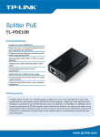
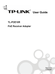
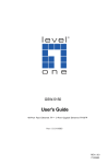
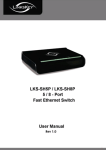
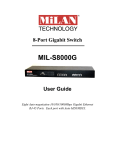
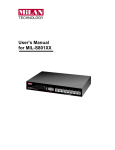
User Guide
TL-SF1008P
8-port 10/100M Desktop PoE Switch
Rev:1.0.0
71035874
COPYRIGHT & TRADEMARKS
Specifications are subject to change without notice.
is a registered trademark of TP-LINK TECHNOLOGIES CO., LTD.
Other brands and product names are trademarks or registered
trademarks of their respective holders.
No part of the specifications may be reproduced in any form or by
any means or used to make any derivative such as translation,
transformation, or adaptation without permission from TP-LINK
TECHNOLOGIES CO., LTD. Copyright © 2008 TP-LINK TECHNOLOGIES CO., LTD. All rights reserved.
http://www.tp-link.com
FCC STATEMENT
This equipment has been tested and found to comply with the limits
for a Class B digital device, pursuant to part 15 of the FCC Rules.
These limits are designed to provide reasonable protection against
harmful interference in a residential installation. This equipment
generates, uses and can radiate radio frequency energy and, if not
installed and used in accordance with the instructions, may cause
harmful interference to radio communications. However, there is no
guarantee that interference will not occur in a particular installation.
If this equipment does cause harmful interference to radio or
television reception, which can be determined by turning the
equipment off and on, the user is encouraged to try to correct the
interference by one or more of the following measures:
•
Reorient or relocate the receiving antenna.
•
Increase the separation between the equipment and
receiver.
•
Connect the equipment into an outlet on a circuit different
from that to which the receiver is connected.
•
Consult the dealer or an experienced radio/ TV technician
for help.
This device complies with part 15 of the FCC Rules. Operation is
subject to the following two conditions:
1) This device may not cause harmful interference.
2) This device must accept any interference received, including
interference that may cause undesired operation.
Any changes or modifications not expressly approved by the party
responsible for compliance could void the user’s authority to operate
the equipment.
CE Mark Warning
This is a class B product. In a domestic environment, this product
may cause radio interference, in which case the user may be
required to take adequate measures.
SAFETY NOTICES
Cautions
Do not use this product near water, for example, in a wet basement
or near a swimming pool.
Avoid using this product during an electrical storm. There may be a
remote risk of electric shock from lightning.
CONTENT
Package Contents...........................................................................1
Chapter 1. Introduction of the Product ........................................1
1.1
Overview of the Product .............................................1
1.2
Convention ...................................................................2
1.3
Features........................................................................2
Chapter 2. Installation ....................................................................3
2.1
Mounting the Switch on a Desk..................................3
2.2
Power On ......................................................................4
Chapter 3. Identifying External Components ..............................4
3.1
Front Panel ...................................................................4
3.2
Rear Panel ....................................................................6
Appendix A: Specifications ...........................................................8
Package Contents
The following items should be found in your box:
¾ One TL-SF1008P 8-port 10/100M Desktop PoE Switch
¾ One DC Power Adapter
¾ Four rubber cushions to be used under the switch
¾ This User Guide
Note
Make sure that the box contains the above items. If any of the listed
items are damaged or missing, please contact with your distributor.
Chapter 1.
Introduction of the Product
Thank you for choosing the TL-SF1008P 8-port 10/100M Desktop
PoE Switch.
1.1 Overview of the Product
The TL-SF1008P 8-port 10/100M Desktop PoE Switch provides the
seamless network connection, which integrates 100Mbps Fast
Ethernet and 10Mbps Ethernet network capabilities.
This PoE Switch is also a Power Sourcing Equipment (PSE*). Four
of the eight Auto-Negotiation RJ45 ports (port-1~port-4) on the
switch support Power over Ethernet (PoE*) function, which can
automatically
detect
and
supply
power
802.3af-complaint powered devices (PDs*).
1
with
those
IEEE
*PSE: a device (switch or hub for instance) that will provide power in a PoE
setup.
*PoE: This technology describes a system to transmit electrical power, along
with data, to remote devices over standard twisted-pair cable in an
Ethernet network.
*PD: a device powered by a PSE and thus consumes energy. Examples include
powering IP telephones, wireless LAN access points, network cameras,
network hubs, embedded computers etc.
1.2 Convention
The Switch or TL-SF1008P mentioned in this User Guide stands for
TL-SF1008P 8-port 10/100M Desktop PoE Switch without any
explanation.
1.3 Features
¾ Complies with IEEE802.3, IEEE802.3u, IEEE802.3af standards
¾ 8 10/100Mbps Auto-Negotiation RJ45 ports with 4-port PoE
function (port-1~port-4), all of them support Auto-MDI/MDIX
¾ Supports PoE power up to 15.4W for each PoE port
¾ Supports PoE power up to 53W for PoE ports
¾ Supports PoE IEEE802.3af compliant PDs
¾ Supports IEEE802.3x flow control for Full-duplex Mode and
backpressure for Half-duplex Mode
¾ 1K entry MAC address table of the TL-SF1008P with autolearning and auto-aging
2
¾ LED indicators for monitoring power, link, activity and speed
¾ External power adapter supply
Chapter 2.
Installation
During the installation procedure, please only use the accessories
equipped with the switch.
2.1 Mounting the Switch on a Desk
To install the Switch, please follow the steps:
1) You can place the Switch on a flat desk.
2) Please insert the power adapter carefully to the power socket of
the switch, and then connect it properly to a power source
through the cable of the switch.
3) Ensure adequate ventilation space around the switch for
dissipating heat and air.
Note
1) Please avoid any heavy thing placed on the switch.
2) Make sure the power is off before unplugging the power
adapter.
3
2.2 Power On
The TL-SF1008P Switch can be used with DC power supply.
Powering on the Switch, it will automatically initialize and its LED
indicators will respond as follows:
1) All the LED indicators except PoE ports LED will light synchronously at first,
then all of them included Link/Act LED
(green), 100Mbps LED (green) and PoE MAX LED (red), will
light off at once, which indicates the system initialized well.
2) The Power indicator will light all the time.
Note
If the LED indicators don’t respond as described above, please
check the power supply and its connection.
Chapter 3.
Identifying External Components
This Chapter describes the front panel, rear panel and LED indicators of the Switch.
3.1 Front Panel
Figure 3-1 TL-SF1008P Switch Front Panel
The Switch’s LEDs are located on the front panel.
4
Name
Status
Indication
Power
On(green)
Off
Power on.
Power off.
There is a PoE PD connected to
the port, which supply power
successfully.
The PoE power circuit may be in
short, or the power current may
be over that of the PD’s
classification.
No PD connected to the
corresponding port,or no power is
supplied according to the power
limits of the port.
On(green)
PoE ports
(port-1~port-4)
On(red)
Off
Flashing
(red)
PoE MAX
On(red)
Off
Flashing
(green)
Link/Act
(port-1~port-8)
On(green)
Off
The power of all the connected
PoE ports is >=53w.
The power of all the connected
PoE ports is >=43w. No power
may be supplied if additional PDs
are connected.
The power of all the connected
PoE ports is <43w, or there is No
PD connected to the
corresponding port.
Data transmitting or receiving on
corresponding port.
There is a 10Mbps or 100Mbps
device connected to the
corresponding port.
No device connected to the
corresponding port.
5
On(green)
100Mbps
(port-1~port-8)
Off
There is a 100Mbps device
connected to the corresponding
port.
There is a 10Mbps device
connected to the corresponding
port, or there is no device
connected to the corresponding
port.
Note
If all PoE PDs power consumption is >= 53w, a priority* will be
arranged among the PoE ports like port-1 > port-2 > port-3 > port-4,
then the system will cut off the power of the lowest-priority port.
*Priority: This function will help protect the system when the system power is
overloaded. For example, Port 1, 2 and 4 is using 15.4w (maximum
power for per port is 15.4W), the system power is 46.2w in total. If
there is an additional PD inserted to Port 3 with 10w, then the system
will cut off the power of Port 4 because of the overloaded power, this
means Port 1, 2 will use 15.4w, and Port3 will use 10w ,no power will
be supplied to Port 4.
3.2 Rear Panel
Figure 3-2 TL-SF1008P Switch Rear Panel
6
The following parts are located on the rear panel:
¾ Power (48V):
48V indicates the input voltage of the power
adapter provided with this TL-SF1008P Switch. The Power socket
is where you will connect the power adapter.
¾ PoE Ports (1-4):
These ports support PoE function which
integrates power and data onto one the same cable. Once the
device you connect to the switch is identified, the switch will
supply power through the PoE port, and then you can use it as a
10/100Mbps Auto-Negotiation RJ45 Ethernet port. The working
status can be indicated by the corresponding LEDs on the front
panel.
¾ Ethernet Ports (1-8): Besides the 4 PoE ports, the TL-SF1008P
Switch is also equipped with the other four 10/100Mbps
Auto-Negotiation RJ45 ports without PoE function. Once the
network devices are connected to these 8 ports through the
network cable, the switch will make them plug and play according
to the Auto-MDI/MDIX detection. The working status can be
indicated by the corresponding LEDs on the front panel.
Note
Make sure the PDs you connected to the switch are complaint with
IEEE 802.3af.
7
Appendix A: Specifications
General
Standard
Topology
Protocol
Data Transfer
Rate
Network
Media(Cable)
Number of Ports
PoE Power on
RJ-45
LED indicators
Transfer Method
MAC Address
Learning
Frame Filter Rate
Frame Forward
Rate
IEEE802.3,IEEE802.3u,IEEE802.3x,IEEE802.3af
Star
CSMA/CD
Ethernet: 10Mbps (Half Duplex)
20Mbps (Full Duplex)
Fast Ethernet: 100Mbps (Half Duplex)
200Mbps (Full Duplex)
10Base-T:
UTP category 3, 4, 5 cable (maximum 100m)
EIA/TIA-568 100Ω STP (maximum 100m)
100Base-TX:
UTP category 5, 5e cable (maximum 100m)
EIA/TIA-568 100Ω STP (maximum 100m)
8 10/100Mbps Auto-Negotiation RJ45 ports with
PoE enabled (port-1 ~ port-4)
Power+: ping 3 & ping 6
Power -: ping 1 & ping 2
Power, Link/Act, 100Mbps
Store-and-Forward
Automatically learning, automatically aging
10Base-T: 14880pps/Port
100Base-Tx: 148800pps/Port
10Base-T: 14880pps/Port
100Base-Tx: 148800pps/Port
8
Environmental and Physical
5.8 watts. (max. no PD connected)
Power Consumption
58 watts (max. with 53w PD connected)
Operating
0 ~40°C (32 ~104°F )
Temperature
Storage Temperature
Operating Humidity
Storage Humidity
-40 ~70°C (-40 ~158°F)
10%~90% non-condensing
5%~95% non-condensing
9