1
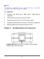
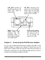
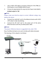
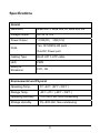
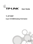
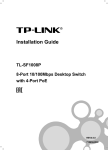
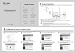
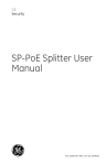
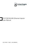
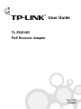
User Guide
TL-POE10R
PoE Receiver Adapter
Rev:1.0.0
71035981
COPYRIGHT & TRADEMARKS
Specifications are subject to change without notice.
is a registered trademark of TP-LINK TECHNOLOGIES CO., LTD.
Other brands and product names are trademarks or registered
trademarks of their respective holders.
No part of the specifications may be reproduced in any form or by any
means or used to make any derivative such as translation, transformation,
or adaptation without permission from TP-LINK TECHNOLOGIES CO.,
LTD. Copyright © 2008 TP-LINK TECHNOLOGIES CO., LTD. All rights
reserved.
http://www.tp-link.com
FCC STATEMENT
This equipment has been tested and found to comply with the limits
for a Class B digital device, pursuant to part 15 of the FCC Rules.
These limits are designed to provide reasonable protection against
harmful interference in a residential installation. This equipment
generates, uses and can radiate radio frequency energy and, if not
installed and used in accordance with the instructions, may cause
harmful interference to radio communications. However, there is no
guarantee that interference will not occur in a particular installation.
If this equipment does cause harmful interference to radio or
television reception, which can be determined by turning the
equipment off and on, the user is encouraged to try to correct the
interference by one or more of the following measures:
¾
¾
Reorient or relocate the receiving antenna.
Increase the separation between the equipment and
receiver.
¾
Connect the equipment into an outlet on a circuit different
from that to which the receiver is connected.
¾
Consult the dealer or an experienced radio/ TV technician
for help.
This device complies with part 15 of the FCC Rules. Operation is
subject to the following two conditions:
1)
This device may not cause harmful interference.
2)
This device must accept any interference received, including
interference that may cause undesired operation.
Any changes or modifications not expressly approved by the party
responsible for compliance could void the user’s authority to operate
the equipment.
CE Mark Warning
This is a class B product. In a domestic environment, this product
may cause radio interference, in which case the user may be
required to take adequate measures.
SAFETY NOTICES
¾
Do not use this product near water, for example, in a wet
¾
Avoid using this product during an electrical storm. There may
basement or near a swimming pool.
be a remote risk of electric shock from lightning.
CONTENTS
Package Contents...........................................................................1
Chapter 1.
Introduction .............................................................1
1.1
Overview of the production .......................................1
1.2
Features ....................................................................2
Chapter 2.
Identifying External Components..........................2
Chapter 3.
Connecting the PoE Receiver Adapter ...................3
Specifications .................................................................................5
Package Contents
The following items should be found in your package:
¾
TL-POE10R PoE Receiver Adapter
¾
One Ethernet (CAT5 UTP) Cable
¾
One Power Cable
¾
This User Guide
) Note:
Make sure that the package contains the above items. If any of the
listed items are damaged or missing, please contact with your
distributor.
Chapter 1. Introduction
1.1 Overview of the production
Thank you for choosing the TL-POE10R PoE Receiver Adapter.
The PoE Receiver Adapter fully complies with IEEE 802.3af
standard, and can work with all IEEE 802.3af PoE compliant PSE
(Power Source Equipment) or PoE Supplier Adapter, such as
TP-LINK’s TL-SF1008P or TL-POE150S, to deliver 12V or 5V Direct
Current to the device which do not support PoE.
PoE (Power over Ethernet) technology allows the existing Ethernet
infrastructure to transmit electrical power, along with data, to remote
IP endpoints over the Ethernet cables, which can greatly save the
cost of the external power cables. Your network can benefit from
PoE technology for it will ensure the normal working status of your
network while keep the existing Ethernet infrastructure secure.
1
) Note:
TL-POE10R is applicable to the device that has no external
connections other than the Ethernet cables.
1.2 Features
¾
Complies with IEEE 802.3, IEEE 802.3u, IEEE 802.3af
standards
¾
Data and Power carried over the same cable
¾
Supports optional 5V DC or 12V DC power supply
¾
Supports Plug-and-Play for the devices,without any configuration
¾
Elegant appearance with space-saving mini size
Chapter 2. Identifying External Components
POWER+DATA IN: Connect to the PSE or PoE Supplier
Adapter with a CAT5 UTP cable.
2
DC OUT: Connect to the
power port of the Ethernet
device with the provided
power cable to supply the
power of 5V or 12V DC.
LAN OUT: Connect to
the Ethernet device with
CAT5 UTP cable to
transmit data.
PWR: Power LED, a
steady green light
indicates that the
connected PSE or
PoE Supplier Adapter
can supply power.
Power-mode switch:
You can choose the
DC output as 12V or
5V by turning the
switch left or right.
Chapter 3. Connecting the PoE Receiver Adapter
You can use TL-POE10R PoE Receiver Adapter with PSE or PoE
Supplier Adapter to expand your network to where there are no
power lines or outlets, where you wish to fix devices such as APs, IP
Cameras or IP Phones, etc. The following steps will tell you how to
connect the PoE Receiver Adapter correctly.
3
1.
Use a CAT5 UTP cable to connect a PoE port of the PSE( ex.
PoE Switch) to the POWER+DATA IN port.
2.
Choose the appropriate DC output by the Power-mode Switch,
default output is 12V.
) Note:
Please make sure that the output is correct, different voltage may
destroy the device.
3.
Connect the LAN OUT port to the Ethernet device with CAT5
UTP cable for data transmitting.
4.
Connect the DC OUT port to the power port of the same
Ethernet device with the provided power cable.
) Note:
The power of Ethernet device is suggested to be under 10W.
Now, the Ethernet device can work normally with data and power.
The topology of this network is as follows:
PoE Switch
TL-SF1008P
CAT5 UTP Cable
Notebook
With Wireless Adapter
(Power & Data)
PoE Receiver Adapter
TL-POE10R
Power Cable
CAT5 UTP Cable
(Data)
PC
4
Wireless AP
TL-WA601G
Specifications
Normal
Standards
IEEE 802.3, IEEE 802.3u, IEEE 802.3af
Voltage Output
DC 5V or 12V
Power Output
11.5W(5V)
Ports
12W(12V)
Two 10/100M RJ45 ports
One DC Power port
Cabling Type
RJ45 CAT 5 UTP cable
LED
PWR
Safety &
Emissions
FCC, CE
Environmental and Physical
Operating Temp.
0℃~40℃ (32℉~104℉)
Storage Temp.
-40℃~70℃ (-40℉~158℉)
Operating Humidity
10%~90% RH, Non-condensing
Storage Humidity
5%~90% RH, Non-condensing
5