1
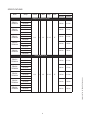
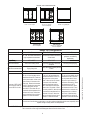
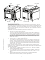
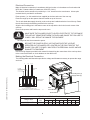
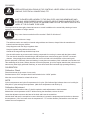
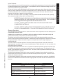
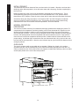
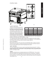
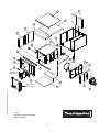
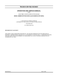
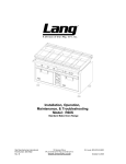
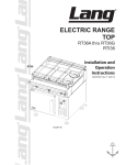
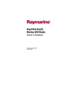
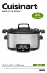
ELECTRIC RANGE
MODEL
TRE36C & TRE36D
Commerical & Marine Applications
Installation and
Operation
Instructions
2M-W1624 Rev. - June. 11, 2010
IL2021
TRE36D5
TRE36C5
SAFETY SYMBOLS
CAUTION
These symbols are intended to alert the user to the presence of
important operating and maintenance instructions in the manual
accompanying the appliance.
WARNING
RETAIN THIS MANUAL FOR FUTURE REFERENCE
NOTICE
Using any part other than genuine Toastmaster factory supplied parts relieves the
manufacturer of all liability.
Toastmaster reserves the right to change specifications and product design
without notice.Such revisions do not entitle the buyer to corresponding changes,
improvements, additions or replacements for previously purchased
equipment.
Due to periodic changes in designs, methods, procedures, policies and
regulations, the specifications contained in this sheet are subject to change
without notice. While Toastmaster exercises good faith efforts to provide
information that is accurate, we are not responsible for errors or omissions
in information provided or conclusions reached as a result of using the
specifications. By using the information provided, the user assumes all risks in
connection with such use.
MAINTENANCE AND REPAIRS
Contact your local authorized service agent for service or required maintenance.
Please record the model number, serial number, voltage and purchase date in the area below and have it
ready when you call to ensure a faster service.
Model No.
Authorized Service Agent Listing
Reference the listing provided with the unit
Serial No.
or
for an updated listing go to:
Voltage
Website:
E-mail Telephone:
Purchase Date
www.toastmastercorp.com
[email protected]
(314) 678-6347
The Service Help Desk
8:00 am to 4:30 p.m. Central Standard Time
Business
Hours:
(314) 678-6347
Telephone:
Fax:
E-mail
Website:
(314) 781-2714
[email protected]
[email protected]
[email protected]
Mailing Address:
2
www.star-mfg.com
Toastmaster
10 Sunnen Drive
St. Louis, MO 63143
U.S.A
Consult One of Our Many Local Qualified Service Agents Before you call
the Toastmaster Technical Service & Parts Department at 1-800-807-9054.
TABLE OF CONTENTS
Specifications . . . . . . . . . . . . . . . . . . . . . . . . . . . . . . . . . . . . . . . . . . . . . . . . . . . . . 4
General Information. . . . . . . . . . . . . . . . . . . . . . . . . . . . . . . . . . . . . . . . . . . . . . . . . 5
INSTALLATION
Range Top Configurations. . . . . . . . . . . . . . . . . . . . . . . . . . . . . . . . . . . . . . . . . . . . . . 6
Equipment Description . . . . . . . . . . . . . . . . . . . . . . . . . . . . . . . . . . . . . . . . . . . . . . . . 7
Recieving the Range. . . . . . . . . . . . . . . . . . . . . . . . . . . . . . . . . . . . . . . . . . . . . . . . . . 8
Location. . . . . . . . . . . . . . . . . . . . . . . . . . . . . . . . . . . . . . . . . . . . . . . . . . . . . . . . . . . . 8
Un-crating. . . . . . . . . . . . . . . . . . . . . . . . . . . . . . . .. . . . . . . . . . . . . . . . . . . . . . . . . . . 8
Installing the Legs . . . . . . . . . . . . . . . . . . . . . . . . . . .. . . . . . . . . . . . . . . . . . . . . . . . . 8
Electrical Connection. . . . . . . . . . . . . . . . . . . . . . . . . . . . . . . . . . . . . . . . . . . . . . . . . . 9
Making the Connection. . . . . . . . . . . . . . . . . . . . . . . . . . . . . . . . . . . . . . . . . . . . . . . . 9
Electrical Specifications. . . . . . . . . . . . . . . . . . . . . . . . . . . . . . . . . . . . . . . . . . . . . . . . 9
Cleaning. . . . . . . . . . . . . . . . . . . . . . . . . . . . . . . . . . . . . . . . . . . . . . . . . . . . . . . . . . 10
Calibration. . . . . . . . . . . . . . . . . . . . . . . . . . . . . . . . . . . . . . . . . . . . . . . . . . . . . . . . . 10
Troubleshooting. . . . . . . . . . . . . . . . . . . . . . . . . . . . . . . . . . . . . . . . . . . . . . . . . . . . . 11
CONVECTION OVEN
Features . . . . . . . . . . . . . . . . . . . . . . . . . . . . . . . . . . . . . . . . . . . . . . . . . . . . . . . . . . 12
Initial Preheat. . . . . . . . . . . . . . . . . . . . . . . . . . . . . . . . . . . . . . . . . . . . . . . . . . . . . . . 13
General Operation. . . . . . . . . . . . . . . . . . . . . . . . . . . . . . . . . . . . . . . . . . . . . . . . . . . 13
Typical Operation. . . . . . . . . . . . . . . . . . . . . . . . . . . . . . . . . . . . . . . . . . . . . . . . . . . . 13
DECK OVEN
Initial Preheat. . . . . . . . . . . . . . . . . . . . . . . . . . . . . . . . . . . . . . . . . . . . . . . . . . . . . . . 14
Normal Operation, Preheat. . . . . . . . . . . . . . . . . . . . . . . . . . . . . . . . . . . . . . . . . . . . 14
Oven Rack. . . . . . . . . . . . . . . . . . . . . . . . . . . . . . . . . . . . . . . . . . . . . . . . . . . . . . . . . 14
Control Panel. . . . . . . . . . . . . . . . . . . . . . . . . . . . . . . . . . . . . . . . . . . . . . . . . . . . . . . 15
3-Heat Swtiches . . . . . . . . . . . . . . . . . . . . . . . . . . . . . . . . . . . . . . . . . . . . . . . . . . . . 15
Pan Placement . . . . . . . . . . . . . . . . . . . . . . . . . . . . . . . . . . . . . . . . . . . . . . . . . . . . . 15
Vent Control. . . . . . . . . . . . . . . . . . . . . . . . . . . . . . . . . . . . . . . . . . . . . . . . . . . . . . . . 15
Timer. . . . . . . . . . . . . . . . . . . . . . . . . . . . . . . . . . . . . . . . . . . . . . . . . . . . . . . . . . . . . 15
EXPLODED VIEW
Range Top . . . . . . . . . . . . . . . . . . . . . . . . . . . . . . . . . . . . . . . . . . . . . . . . . . . . . . 16 - 17
Deck Oven . . . . . . . . . . . . . . . . . . . . . . . . . . . . . . . . . . . . . . . . . . . . . . . . . . . . . . 18 - 19
Convection Oven . . . . . . . . . . . . . . . . . . . . . . . . . . . . . . . . . . . . . . . . . . . . . . . . . 20 - 23
WIRING DIAGRAM
Convection Oven w/Range Top 208/240V.. . . . . . . . . . . . . . . . . . . . . . . . . . . . . . . . 24
Convection Oven w/Range Top 480V . . . . . . . . . . . . . . . . . . . . . . . . . . . . . . . . . . . 24
Deck Oven w/Range Top 208/240v . . . . . . . . . . . . . . . . . . . . . . . . . . . . . . . . . . . . . 25
Deck Oven w/Range Top 480V . . . . . . . . . . . . . . . . . . . . . . . . . . . . . . . . . . . . . . . . 25
Warranty. . . . . . . . . . . . . . . . . . . . . . . . . . . . . . . . . . . . . . . . . . . . . . . . . . . . . . . . . . 27
NOTICE
Service on this or any of our other units must be performed by a qualified personnel
only. Consult your Service Agent Directory. You can call our toll free number 1-800807-9054 or visit our website WWW.STAR-MFG.COM for the service agent nearest you.
SPECIFICATIONS
Model
Voltage
Total kW Ph
Width
Height
Depth
Weight
Shipping
Installed
525 lbs
417 lbs
485 lbs
377 lbs
525 lbs
417 lbs
430 lbs
322 lbs
495 lbs
387 lbs
525 lbs
417 lbs
485 lbs
377 lbs
525 lbs
417 lbs
430 lbs
322 lbs
495 lbs
387 lbs
Range Convection Oven
TRE36C1 /
TRE36C1M
TRE36C2 /
TRE36C2M
TRE36C3 /
TRE36C3M
TRE36C4 /
TRE36C4M
TRE36C5 /
TRE36C5M
208V/60Hz
240V/60Hz
480V/60Hz
208V/60Hz
240V/60Hz
480V/60Hz
208V/60Hz
240V/60Hz
21.0
3
36”
37 1/4”
37”
480V/60Hz
208V/60Hz
240V/60Hz
480V/60Hz
208V/60Hz
240V/60Hz
480V/60Hz
Range Deck Oven
TRE36D2 /
TRE36D2M
TRE36D3 /
TRE36D3M
TRE36D4 /
TRE36D4M
TRE36D5 /
TRE36D5M
208V/60Hz
240V/60Hz
480V/60Hz
208V/60Hz
240V/60Hz
480V/60Hz
208V/60Hz
240V/60Hz
21.6
3
36”
37 1/4”
37”
480V/60Hz
208V/60Hz
240V/60Hz
480V/60Hz
208V/60Hz
240V/60Hz
480V/60Hz
2M-W1624 TM 36” RANGE OP MANUAL
TRE36D1 /
TRE36D1M
GENERAL INFORMATION
CAUTION
This equipment is designed and sold for commercial use only by personnel trained and
experienced in its operation and is not sold for consumer use in and around the home nor for
use directly by the general public in food service locations.
Before using your new equipment, read and understand all the instructions & labels associated with
the unit prior to putting it into operation. Make sure all people associated with its use understand the
units operation & safety before they use the unit.
All shipping containers should be checked for freight damage both visible and concealed. This unit
has been tested and carefully packaged to insure delivery of your unit in perfect condition.
If equipment is received in damaged condition, either apparent or concealed, a claim must be made
with the delivering carrier.
Concealed damage or loss - if damage or loss is not apparent until after equipment is unpacked, a
request for inspection of concealed damage must be made with carrier within 15 days. Be certain to
retain all contents plus external and internal packaging materials for inspection. The carrier will make
an inspection and will supply necessary claim forms.
INSTALLATION
This unit is equipped for the voltage indicated on the nameplates mounted on the right side of the
range. They will operate on alternating current (AC) only.
DO NOT CONNECT TO DIRECT CURRENT (DC).
WARNING
The installation of the electric range should conform to the:
NATIONAL ELECTRIC CODE AND ALL LOCAL ELECTRIC CODES AND
ORDINANCES AND THE LOCAL ELECTRIC COMPANY RULES AND
REGULATIONS
For your protection we recommend that a qualified electrician install this range. They should be
familiar with electrical installations and all electric codes. Proper connections and power supply are
essential for efficient performance. The external wiring should be in conduit or an approved type
of flexible cable suitable for operation at the temperature indicated on the wiring diagram, and of a
proper size to carry the load. The supply circuit should be properly fused and equipped with a means
of disconnecting, as required by local electrical code. THE BODY OF THE RANGE SHOULD BE
GROUNDED (DO NOT GROUND TO A GAS SUPPLY LINE).
2M-W1624 TM 36” RANGE OP MANUAL
GENERAL OPERATING PROCEDURES
The Toastmaster series electric range is wired for operation for 3-phase power supplies by making
line connections at the terminal block, located on the bottom panel, behind the right side panel. All
connections should be made by a qualified service agent. Refer the the Electrical Connection section
& wiring diagram sections of this manual for more information.
Before operating the unit, any rust preventative material needs to be removed from the surface using
a nonflammable grease solvent. Once completed, wash the surface with warm water and a mild
detergent, rinse with a damp cloth and dry wipe dry. Griddle surface must be seasoned immediately,
refer to your company guidelines or the seasoning section of this manual.
DANGER:
WARNING
THIS APPLIANCE MUST BE GROUNDED AT THE TERMINAL PROVIDED.
FAILURE TO GROUND THE APPLIANCE COULD RESULT IN ELECTROCUTION
AND DEATH.
INSTALLATION OF THE UNIT MUST BE DONE BY PERSONNEL QUALIFIED
TO WORK WITH ELECTRICITY. IMPROPER INSTALLATION CAN CAUSE
INJURY TO PERSONNEL AND/OR DAMAGE TO EQUIPMENT. UNIT MUST BE
INSTALLED IN ACCORDANCE WITH ALL APPLICABLE CODES.
RANGE TOP CONFIGURATION
TRE36C1/D1
TRE36C2/D2
Three 12” x 24” hot tops
TRE36C3/D3
Two 12” x 24” hot tops
Two round hotplates
TRE36C4/D4
One 36” x 24” griddle plate
TRE36C5/D5
Six round hotplates
IL2020
One 24” x 24” griddle plate
Two round hotplates
Range Top Configurations
Hot Plates
Round French Plates
12” x 24” Hot Plates controlled by Round French Plates controlled by
high temperature thermostats.
3 heat switch.
Temp Range
Recommended:
Not-Recommended
Griddle Plates
36” x 24” or 24” x 24”
grill plates, controlled by
thermostats.
0°F to 850°F
0°F to 750°F
0°F to 450°F
Stock Pots & Heavy Kettle
Light duty sauce pans and small
stockpots.
All heavy and light frying.
Frying of any kind
Heavy Stock Pots or Heavy Urns or
Kettles
To “dry out” the hot plate, set the
thermostat dial at 250°F and turn
on the power switch. Allow unit to
cycle at least 15 minutes at this
heat level. Reset the thermostat
Element “DRY OUT”
to 350°F allowing the same time.
to be done with a
Continue doing this until you
non-GFCI circuit
reach 850°F then allow the unit
to maintain this temperature for a
minimum of 4 hours. More time
may be required if the unit has to
operate in a moist enviroment
To “dry out” the frenchplate, set
the three-heat switch to the “LO”
setting and turn on the power
switch. Allow unit to run at least
15 minutes at this heat level.
Reset the three-heat switch to
“MED” and allow the same time.
Reset to the “HI” position. When
you reach position 3, allow the unit
to maintain this temperature for a
minimum of 4 hours. More time
may be required if the unit has to
operate in a moist enviorment
To “dry out” the griddle, set the
thermostat to 250°F and turn
on the power switch. Allow
the unit to cycle at least 15
minutes at this setting. Reset
the thermostat to 350°F
allow the same time. Reset
the thermostat to 450°F and
allow the unit to maintain the
temperature for a minimum
of 4 hours. More time may
be required if the unit has to
operate in a moist enviroment.
If unit is out of use for three or more days, a one-hour preheat schedule should be used, especially when
exposed to high humidity and/or cool temperatures.
NOTICE: During the first few hours of operation you may notice a small amount of smoke & odor coming from the range.
This is normal for a new range and will disappear after the first few hours of use.
2M-W1624 TM 36” RANGE OP MANUAL
The below procedure is to be followed in situations when the circuit trips when unit is turned on.
Griddle
French Plates
Hot Plate
IL2022
Deck Oven
Circuit Breakers
Convection Oven
EQUIPMENT DESCRIPTION
Toastmaster Model TRE36 electric oven range are rated heavy duty for commercial use. The oven
range consists of a range top fastened to an oven base. There are marine units available which would
qualify it for shipboard use. These models are indicated with a “M” in the model number The marine
features are on oven door latch, grease tray latch, bolt-down legs, range top adjustable sea rails and a
grab bar across the front.
OVEN BASE: The oven base can be either a deck oven or convection oven.
a. Deck Oven (“D in Model #, example TRE36D1)
The deck oven base has a aluminized steel inner lining, removable deck of rigidized steel,
vent with damper and landing shelf type aluminized steel lined door. The oven is insulated
on all sides and is equipped with one slide-in rack. Heating is accomplished with top and
bottom formed tubular heating elements which are each controlled by a 3-heat (low, medium,
high) switch. The deck oven has a thermostatic control with a temperature range of 200°F
to 550°F (93°C to 287°C).
2M-W1624 TM 36” RANGE OP MANUAL
b. Convection Oven (“C” in Model #, example TRE36C1)
The convection oven has aluminized steel oven liners, vent damper and aluminized steel
lined door. The oven is insulated on all sides. Removable rack supports can accommodate
three racks. The heating element is enclosed in the side of the oven cavity and encircles the
oven blower fan. The convection oven has a thermostatic control with a temperature range
of 100°F to 450°F (38°C to 232°C).
RANGE: The range top can consist of up to 3 different components and the components can be
configured in five ways. Troughs with a drip chute are located in the front and rear for draining into two
wide drawer type receptacles
a. Griddle: for grilling. The griddle can be either 24” x 24” or 24” x 36”. Each of the 12” griddle
sections are thermostatically controlled.
b. 12” x 24” Hot Plate: for stock pot cooking (Not recommended for griddling). The hot plates
are thermostatically controlled and have a temperature range of 250°F to 850°F (121°C to
454°C).
c. Round Hot Plate (French Plates): for stock pot cooking. The twin hot plates have 9”
diameter and are controlled by 3-heat (low, medium, high) switches.
Receiving the Range
Upon receipt, check for freight damage, both visible and concealed. Note
visible damage on the freight bill at the time of delivery and require the
carrier’s agent to sign the freight bill. Concealed loss or damage means loss
or damage, which does not become apparent until the merchandise has
been unpacked. If concealed loss or damage is discovered upon unpacking,
make a written request for inspection by the carrier’s agent within 15 days
of delivery. Keep all packing material for inspection. Do not return damaged
merchandise to Toastmaster. File your claim with the carrier.
Location
Prior to un-crating, move the range as near its intended location as practical.
The crating will help protect the unit from the physical damage normally associated with moving it
through hallways and doorways.
The clearances to combustable surfaces must be maintained: 3 inches from the back & sides.
Un-crating
The unit will arrive unassembled inside a wood frame covered by cardboard box and strapped to a
skid. Remove the cardboard cover, cut the straps and remove the wood frame.
CAUTION
RANGE IS VERY HEAVY AND FOR SAFE HANDLING, INSTALLER SHOULD
OBTAIN HELP AS NEEDED, OR EMPLOY APPROPRIATE MATERIALS
HANDLING EQUIPMENT (SUCH AS A FORKLIFT, DOLLY, OR PALLET JACK)
TO REMOVE THE UNIT FROM THE SKID AND MOVE IT TO THE PLACE OF
INSTALLATION.
ANY STAND, COUNTER OR OTHER DEVICE ON WHICH RANGE WILL BE
LOCATED MUST BE DESIGNED TO SUPPORT THE WEIGHT OF THE OVEN.
CAUTION
SHIPPING STRAPS ARE UNDER TENSION AND CAN SNAP BACK WHEN CUT.
Remove range from skid and place in intended location.
Installing the Legs
To install the 6-inch legs, remove
the legs from the packing, place
some cardboard on the floor and
gently tip the oven onto its back.
Fasten the legs into the threaded
holes provided and then gently flip
the oven onto its legs.
IL2023
2M-W1624 TM 36” RANGE OP MANUAL
Legs ship standard with all ranges.
Electrical Connection
Make all electrical connections in accordance with local codes or in the absence of local codes with
NFPA No. 70 latest edition (in Canada use: CSA STD. C22.1).
The electrical service entrance is provided by a 1 1/4” knockout on the oven bottom. A three pole
terminal block is provided for connection.
Place spacers, (i.e. 2x4 wood block not supplied) at the front and rear of the oven top.
Place the range top on the spacers that are located on top of the oven.
The six wire leads that supply electricity to the cook top are bundled under the front of the top. Route
the six wires through the bushing provided in the oven top.
Align the four locating pins in the bottom corner of the top with the four holes in each corner of the
oven top.
Remove the spacers and lower the top onto the oven.
MAKE SURE THE SIX WIRE LEADS TO SUPPLY ELECTRICITY TO THE RANGE
TOP ARE NOT CRIMPED BETWEEN THE OVEN AND RANGE TOP. FAILURE TO
COMPLY WILL RESULT IN DAMAGE TO EQUIPMENT.
WARNING
The range can now be connected to power.
BE SURE THE POWER SUPPLY VOLTAGE MATCHES THE VOLTAGE
SPECIFIED ON THE NAMEPLATE LOCATED ON THE RIGHT SIDE OF THE
RANGE. FAILURE TO COMPLY MAY RESULT IN PERSONAL INJURY AND/OR
DAMAGE TO EQUIPMENT
WARNING
Use the wiring diagram provided in this manual for determining the connections of the cook top wires
to the oven terminal block or circuit breakers on the 480V units.
Making the Electrical Connection
The following table and illustrations provide the voltage and kilowatts necessary to operate the range
and oven.
3
1,5
2,4,6
TO OVEN
TO RANGE
TOP
Locating Pins (4)
2M-W1624 TM 36” RANGE OP MANUAL
Supply Wires (6)
TERMINAL BLOCK
IN OVEN BASE
Three Phase
NOTE: 480V UNITS GET WIRED DIRECTLY INTO
THE CIRCUIT BREAKER IN THE OVEN, REFER TO WIRING DIAGRAM.
IL2024
480V
Circuit Breaker
IL2025
Terminal Block
Range Style
w/ CONVECTION OVEN
w/ DECK OVEN
ELECTRICAL SPECIFICATIONS
208 Volt
240 Volt
Total
k.W.
L1
L2
L3
L1
L2
L3
21.6
48.3 69.2 62.5 41.9 59.9 54.1
21.0
45.8 66.7 62.5 39.7 57.8 54.1
480 Volt
L1
L2
L3
20.5 29.5 27.1
19.9 28.9 27.1
CLEANING
WARNING
CAUTION
KEEP WATER AND SOLUTIONS OUT OF CONTROLS. NEVER SPRAY OR HOSE CONTROL
CONSOLE, ELECTRICAL CONNECTIONS, ETC.
MOST CLEANERS ARE HARMFUL TO THE SKIN, EYES, MUCOUS MEMBRANES AND
CLOTHING. WEAR RUBBER GLOVES, GOGGLES OR FACE SHIELD AND PROTECTIVE
CLOTHING. CAREFULLY READ THE WARNING AND FOLLOW THE DIRECTIONS ON THE
LABEL OF THE CLEANER TO BE USED.
The range should be thoroughly cleaned at least once a week in addition to the normal daily cleaning to insure
against the accumulation of foreign material.
CAUTION
Any oven cleaner used should be marked “Safe On Aluminum”.
Always start with a cold oven / range
The stainless exterior can easily be cleaned using stainless steel cleaner, always follow the manufacture’s
instructions when using any cleaner.
Keep-drip pans under the range top plates clean.
Keep the hotplate and griddle surfaces clean.
Outside of the range and top should be kept clean.
Care should be taken to prevent caustic cleaning compounds from coming in contact with the blower wheel.
The oven interior should be cleaned using a mild soap and a non metal scouring pad. DO NOT use caustic
cleaners. Always apply these cleaners when the oven is cold and rub in the direction of the metal’s grain.
Electric equipment is inherently clean and sanitary, but may become unsanitary if dirt is allowed to accumulate on it.
Take advantage of the clean, sanitary features of electric equipment, give it the regular attention that it deserves the
same as any other highly perfected machinery, to insure best results and continued high operating efficiency.
CALIBRATION
Calibration Check
Place thermometer in the center of oven cavity.
Allow the oven to Preheat for at least half an hour.
NOTE
Cycle on temperatures and cycle off temperatures for 3 cycles. (Red indicator light indicates when oven is calling for
heat) After 3 cycles average the temperature. (Add all six temperatures and divide by 6)
Calibration Adjustment
A 1/16” flat blade screwdriver with a 2” shaft is required to make adjustments to the thermostat.
Maintain the oven temperature at 350°F. Without turning the thermostat, remove the knob.
Locate the adjustment screw at the base of the shaft and insert the screwdriver.
Hold the shaft and turn the screwdriver counter clockwise to increase the temperature and clockwise to decrease
the temperature. (1/8 of a turn will move the temperature 5-7 °F in either direction). Reinstall the oven knob and
recheck the oven temperature.
10
2M-W1624 TM 36” RANGE OP MANUAL
Set thermostat to 350°F and place both 3-heat switches in the “HIGH” position.
TROUBLESHOOTING
Troubleshooting is not an exact science, several factors may play a part in why your unit is not operating correctly.
The following symptoms are a general idea of what may be causing the malfunction and should not be considered the
complete answer to the situation that you have with your machine. Here are some of the possible problems you may
encounter and possible solutions to those problems.
TESTS
NOTICE:
WARNING
Service on this or any other appliance must be performed by qualified personnel only.
Consult your Toastmaster Authorized Service Agent Directory. You can call our toll free
number 1-800-264-7827 or visit our website WWW.STAR-MFG.COM for the service agent
nearest you.
BOTH HIGH AND LOW VOLTAGES ARE PRESENT INSIDE THIS APPLIANCE WHEN THE
UNIT IS PLUGGED/WIRED INTO A LIVE RECEPTACLE. BEFORE REPLACING ANY PARTS,
DISCONNECT THE UNIT FROM THE ELECTRIC POWER SUPPLY.
If an item on the list is followed by an asterisk (*), the work should be done by a factory authorized service
representative.
CAUTION
USE OF ANY REPLACEMENT PARTS OTHER THAN THOSE SUPPLIED BY TOASTMASTER
OR THEIR AUTHORIZED DISTRIBUTORS CAN CAUSE BODILY INJURY TO THE OPERATOR
AND DAMAGE TO THE EQUIPMENT AND WILL VOID ALL WARRANTIES
RANGE TOP TROUBLESHOOTING
Symptom
Hotplate will not heat
French Plate will not heat
2M-W1624 TM 36” RANGE OP MANUAL
Griddle plate will not heat
Possible Causes
Possible Causes
No power to unit
Defective thermostat
Failed element
No power to unit
Failed 3-heat switch
Failed element
No power to unit
Failed thermostat
Failed element
Test
Failed Thermostat
Failed element
Verify calibration
Remove the wires and check for continuity across the element*
Failed 3-heat switch
Call factory or consult service manual for proper test
11
The oven exterior dimensions are 36” (91.44cm) Wide, 22” (55.88cm) High, 34” (86.36cm) Deep.
The Front, Back, and Sides are constructed of stainless steel with an aluminized top and bottom
The oven cavity is insulated with high temperature insulation for efficiency and reduced heat loss.
Interior Construction
The oven cavity dimensions are 20” (50.8cm) Wide, 17” (43.18cm) High, 29” (73.66cm) Deep.
The oven is designed for three shelves and comes with three Chrome Plated Racks.
The interior of the oven is constructed of aluminized steel.
Operation
The oven is a forced air convection oven with a vented oven cavity.
The air is driven by a 1/3 HP fan motor.
Controls
Easy to use manual control knobs.
Mechanical temperature sensing and controls.
Technical
Oven operates as shipped on 208, 240, or 480-Volt Three Phase.
Floor space required is 42” (106.68cm) Wide, 37” (94cm) Deep.
The oven weighs 275 lb.
.
Timer
Vent Knob
Temperature
VENT
TIMER
TEMPERATURE
POWER
ON
OFF
HEATING
ON
FUSES
Power
Switch
Circuit Breaker Panel
12
IL2028
2M-W1624 TM 36” RANGE OP MANUAL
CONVECTION OVEN
FEATURES
Exterior Construction
Prior to putting any oven into full time operation at normal cooking temperatures, it must be thoroughly dried
out. Moisture absorption in the closed spaces, in the insulation, and even inside the heating elements can
cause future trouble if not properly treated.
To “dry out” the oven, set the thermostat to 250°F and turn on the power switch. Allow the unit to cycle at
least 15 minutes at this heat level. Reset the thermostat to 350°F allow the same time. Reset the thermostat
to 450°F and allow the unit to maintain the temperature for a minimum of 4 hours. More time may be
required if the unit has to operate in moist environment.
If the unit is out of use for three or more days, a one-hour preheat schedule should be used, especially
when exposed to high humidity and/or cool temperatures.
NOTICE: During the first few hours of operation you may notice a small amount of
smoke coming from the oven, and a faint odor from the smoke. This is normal for
a new range and will disappear after the first few hours of use.
CAUTION: ALWAYS KEEP THE AREA NEAR THE APPLIANCE FREE FROM
COMBUSTIBLE MATERIALS.
CAUTION: KEEP FLOOR IN FRONT OF EQUIPMENT CLEAN AND DRY. IF SPILLS
OCCUR, CLEAN IMMEDIATELY, TO AVOID THE DANGER OF SLIPS OR FALLS.
General Operation
The convection oven roasts and bakes in shorter time and at lower temperatures with less shrinkage than
conventional commercial ovens.
A blower in the convection oven circulates air within the chamber to heat the entire space evenly and
transfer heat efficiently to the product, even with stacked loading.
The airflow continuously removes the thick layer of moist, cool air that otherwise would surround the
product. When properly loaded and operated, it maintains this airflow throughout the chamber to eliminate
hot spots and roasts or bakes with minimum power consumption at twice the output capacity of a
conventional oven.
The power switch on the lower portion of the control panel energizes the fan motor and activates the
thermostatically controlled circuit for the oven heating elements. When this switch is in the on position, the
red indicator light will illuminate.
2M-W1624 TM 36” RANGE OP MANUAL
Rotating the thermostat control knob from “off” position to selected temperature causes the indicator light
to illuminate and closes the contactor that feeds power to the heating elements. This light will cycle “on
and off” as the thermostat calls for heat in the oven. The blower, however, operates continuously while the
power switch is in the “on” position.
The black knob operates a damper in the oven vent stack. The damper is open when the vent knob is
pulled outward, this will remove moisture from the bake and will provide a dryer bake. Close the vent to
contain the moisture in the bake.
Circuit breakers behind the control panel protect the electrical components from overload. On 208/240V
units the circuit breakers are located in both the range top and oven, 480V units all circuit breakers are in
the oven.
CONVECTION OVEN TYPICAL OPERATION
ACTION
RESULT
Turn power switch to ON
Control Panel heat call light comes on.
Adjust proper temperature, between 140°F - 450°F and allow
preheating for 20 minutes.
Oven begins heating
Open oven doors and insert product. Set timer for up to 60
minutes.
Timer begins counting down
Timer rings when done.
Product should now be done.
13
CONVECTION OVEN
Initial Preheat
INITIAL PREHEAT
Before the initial use of the oven it must be allowed to thoroughly dry the elements out. This is
accomplished by setting the top and bottom oven 3-heat switches to the “Low” position and the
thermostat to 350°F degrees. Allow the oven to heat until all vapor and smoke has been eliminated.
Somewhere along the rising temperature curve between 250°F and 350°F degrees a moderate
amount of smoke will issue from within the oven. Preservative oils and oil accumulated during
manufacture will come off as smoke at these temperatures. Do not be alarmed.
NORMAL OPERATION
PREHEATING
The oven will not bake uniformly if not allowed to thoroughly preheat before loading the product. To
compensate for the temperature loss during loading, set the oven thermostat 50° degrees over the
desired cooking temperature, load the oven, then reset the thermostat to the proper temperature
after closing the oven door. The oven can be preheated with the 3-heat switches set on any position,
however, the fastest preheat will be accomplished with both the switches set to the “High” position.
Once the oven is at the set temperature and the product is loaded reset the 3-heat switches to their
proper setting. An indicator light, located below the oven thermostat knob, will go out once the oven
has received the set temperature. Allow the oven indicator lamp to cycle on and off at least two times
during the preheat.
OVEN RACK
The oven is equipment with a removable rack as standard. Baking pies, bread, or for roasting
operations the rack can be placed directly on the metal deck and the pans placed on the rack. For
cakes or pastries the rack can be slid into the rack supports, located about halfway up the oven sides,
and the pans placed on the rack in this raised position.
OVEN RACK
DECK
DOOR REMOVED FOR CLARITY
14
IL2033
2M-W1624 TM 36” RANGE OP MANUAL
DECK OVEN
The preservatives must be cleaned off the oven front before it is heated. Wipe the oven front with a
damp rag and a mild soap solution, rinse with warm water and a damp rag, and then completely dry
the oven front.
CONTROL PANEL
TEMPERATURE
UPPER
DECK OVEN
VENT
LOWER
TIMER
INICATOR LIGHT
IL2032
3-HEAT SWITCHES
2M-W1624 TM 36” RANGE OP MANUAL
While the oven thermostat controls the
Class of
Average
Switch
temperature, the 3-heat switches control
Rack Position
product Temperature Settings
the amount of power from the upper and
Pie
375-425°F
Medium
On Deck
lower elements. Setting the top element
Rolls
375-400°F
High
Rack
Support
3-heat switch to “High” will burn (or broil)
Cake
350-400°F
High
Rack Support
the tops and setting the bottom 3-heat
Pastries
325-375°F
High
Rack Support
switch to “Low” will not cook the bottom of
Bread
425-450°F
Medium
On Deck
most products. Set the 3-heat switches
to achieve the best uniformity between
Roast
300-325°F
Medium
On Deck
the top and bottom of the product. Best
results for baking will be accomplished with the top 3-heat switch set to the “Low” position and
the bottom 3-heat switch set to either “Medium” or “High”.
The Temperature Switch Setting and Rack Position chart is suggested as a guide in baking
the various classes of product. Be aware this chart is only a suggestion. Correct temperature,
switch settings and rack positions will be arrived at through experience.
PAN PLACEMENT
Place the pan in the center of the oven rack for the best baking results. Keep the oven door
closed as much as possible. Excessively opening the oven door will cool the front section of
the oven and the products placed near the opening will bake slower.
VENT CONTROL
The oven is supplied with an oven vent control located above the thermostat dial. If cooking
products with high moisture content open the vent by pulling the knob out. The moisture will be
vented out the back of the oven as steam. If the products require a moist baking environment
push the vent damper closed.
TIMER
A 60 minute mechanical timer is standard equipment for the TRE36D units. To set, turn the
dial until the indicator line is aligned with the desired time on the control panel. If setting the
timer for less than 10 minutes the dial must first be turned past the 10 minute mark then reset
to the required time. Once the timer has timed-out it will sound a bell for about 5 seconds then
automatically turn off.
15
1
2
3
4
5
6
7
8
9
10
11
12
13
14
15
16
17
18
19
20
21
22
Toastmaster Electric Range Top TRE36 Series
Part Number
P9-50401-02
P9-50401-03
2N-11120-12
2N-11120-13
2N-11120-14
P9-50300-82-1
PS-11010-341
PS-11010-351
PS-11010-361
2N-11010-09
2N-11010-21
2N-11010-23
2N-11010-10
2N-11010-22
2N-11010-24
P9-50300-42
P9-50300-41
P9-50300-22
P9-50300-43
N2-RF21-415-W4
N2-RF21-414-W3
Q9-RF21-423-2
Q9-RF21-423-21
P9-RF21-228
2E-31800-01
2E-30304-W35
2T-30402-23
2T-30402-08
N2-RF21-305-W3
N2-RF21-306-W3
N2-RF21-304-W3
2M-60301-W178
2M-60301-W179
2M-60301-W180
2M-60301-W181
2M-60301-W182
2J-31601-01
2J-31601-02
N2-70701-W62
Description
SMOOTH RANGE PLATE ASSY 1/2 X 2’
SMOOTH RANGE PLATE ASSY 1/2 X 3’
ELMNT TK 208V 2600W
ELMNT TK 240V 2600W
ELMNT TK 480V 2600W
EGO PLATE FRM ASY PHANT
HOTPLATE 208V 5000W CAST
HOTPLATE 240V 5000W CAST
HOTPLATE 480V 5000W CAST
ELMNT T/P 208V 2KW O/S
ELEMT T/P 240V 2KW O/S
ELEMT T/P 480V 2KW O/S
ELMNT T/P 208V 3KW I/S
ELMNT T/P 240V 3KW I/S
ELEMT T/P 480V 3KW I/S
ZIG ZAG ASSY W SNOUT
ELEM PAN ASSY W/SNOUT
208-240V 3/16 STAT BULB HLDR
480V 3/16 BULB HLDR
PAN ASSY A/L - TM
MARINE PAN ASSY - TM
SWITCH DOOR ASSY 208V-430
SWITCH DOOR ASSY 480V-430
CIRCUIT BREAKER COVER
CB 250V50A 1 POLE CRLNGSW
SWITCH - 3 POS ROTARY EGO
STAT ADJ 850o 48C/T NAK
STAT ADJ 450°F
CONTROL PANEL TM - 1 & 3
CONTROL PANEL TM - 2 & 5
CONTROL PANEL TM - 4
LABEL-CNTL PANEL TM RT 1
LABEL-CNTL PANEL TM RT 2
LABEL-CNTL PANEL TM RT 3
LABEL-CNTL PANEL TM RT 4
LABEL-CNTL PANEL TM RT 5
PILOT LT 250V 6LEAD BLK
PILOT LT 480V 6LEAD BLK
KNOB ASSY-TM RANGE TOP
Application
N2-70701-W61
KNOB ASSY-TM RANGE TOP
GRIDDLES
N2-70701-W63
P9-50300-44-1
P9-60102-93
P9-50302-301
P9-50302-303-1
KNOB ASST-TM RANGE TOP
GRAB BAR ASSY 36 RANG
MARINE LATCH ASSY
SEARAIL ASSY 3’
SEARAIL ASSY 1’
ROUND PLATES
MARINE
MARINE
MARINE
MARINE
208V
240V
480V
208V
240V
480V
208V
240V
480V
208V
240V
480V
208/240V
480V
NON MARINE
MARINE
208/240V
480V
208/240V
208/240V
ROUND PLATES
HOTPLATES
GRIDDLES
TRE36C1, D1, C3, D3
TRE36C2, C5, D2, D5
TRE36C4, D4
TRE36C1 / TRE36D1
TRE36C2 / TRE36D2
TRE36C3 / TRE36D3
TRE36C4 / TRE36D4
TRE36C5 / TRE36D5
208/240V
480V
HOTPLATES
2M-W1624 TM 36” RANGE OP MANUAL
Fig No.
1
MARINE APPLICATIONS
2
3
4
22
21
20
16
19
18
17
15
14
13
5
6
7
12
2M-W1624 TM 36” RANGE OP MANUAL
11
10
MODEL: TRE36 RANGE TOP
IL2026, Rev. -, 5/27/2010
8
9
3
4
5
6
7
8
9
10
11
12
13
14
16
NI
NI
NI
Part Number
2A-50800-07
2A-LA36-145
2A-LA36-146
2A-3013164
2E-30304-W35
2E-31800-01
2E-31800-04
2H-60106-31
2J-30801-01
2J-31601-01
2J-31601-02
2M-60301-W02WL
2M-60301-W183
2P-51001-01
2P-51001-02
2R-50312-79-W2
2T-30402-07
N2-50312-33-W2
N2-70701-W64
N2-70701-W65
N2-70701-W66
N9-LA36-116
N2-LA36-130-W1
N2-LA36-142-W1
Q9-50312-81
OVEN DOOR & CONTROL PANEL
Qty
2
2
2
2
2
2
1
1
1
1
1
1
1
1
1
1
1
1
1
2
1
1
1
1
1
Description
TENSION DISC STD OVEN
DOOR RODS LA36
DOOR PIPE LA36
SPACER, DOOR & DRAWER HND
SWITCH - 3 POS ROTARY
CB 250V50A 1 POLE CRLNGSW
CB 480V 50A 3-POLE
INSULATION DOOR
TIMER MECHANICAL LONG
PILOT LT 250V 6LEAD BLK
PILOT LT 480V 6LEAD BLK
LABEL-W/D TM RANGE
LABEL-CNTL PANEL TM DO
SPRING OVN LH DOOR
SPRING OVN RH DOOR
HANDLE-DOOR TM DECK OVEN
STAT ADJ 550o 48 C/T
DOOR OUTSIDE PANEL ASSY - TM
KNOB ASSY-TM OVEN TIMER
KNOB ASSY-TM OVEN 3POS SW
KNOB ASSY-TM OVEN TSTAT
VENT PIPE ASSY
CONTROL SLIDE ASSY-W1
DOOR INSIDE PANEL A/L-TM
BREAKER HOLDER
18
Application
(mounted w/2 screws)
208V(M), 240V (M)
480V (M)
208V (M)
480V (M)
2M-W1624 TM 36” RANGE OP MANUAL
Fig No
1
2
TRE36D 36” BAKE DECK OVEN MAIN ASSEMBLY
Part No
Qty
Description
Application
2C-20103-02
37 SCRW SM PLT 10 X .5 PHLSL
N9-LA36-159
1
TOP LA OVEN S/S
2N-11050-25
ELE 36OVN 240V O/S 1.8KW
240V
2N-11050-29
2
ELMNT 36” OVEN 480V O/S
480V
2N-11050-31
ELE 36”OVN 208V O/S 1.8KW
208V
2N-11050-26
ELE 36OVN 240V I/S 1.2KW
240V
2N-11050-30
2
ELMNT 36” OVEN 480V I/S
480V
2N-11050-32
ELE 36”OVN 208V I/S 1.2KW
208V
P9-50301-09
12 LONG ELEMENT CLIP S/S
P9-50301-10
12 SHORT ELEMENT CLIP
2C-20301-15
8
NUT HEX 10-32 PLTD
N9-LA36-109-1
1
CAPILLARY SHIELD
2P-70901-05
1
PLGBTNBLKPLSTC 3/4DP-750
2E-31200-02
1
LUG GROUNDING UL APPROVED
2C-20103-01
2
SCRW SM PLT 10X7/8 PHIL
2E-30500-07
1
TRM BLOCK 3PLELRGE 125AMP
N9-LA36-128
1
SWITCH DOOR ASSY
N2-LA36-193-W2
1
DOOR ASSY A/L
N9-LA36-184
1
DECK CHANNEL ASSY A/L
2A-72500-06
4
LEG 5 1/2 W/BOLT DOWN ADJ
Marine
2B-50200-09
1
RACK 36 OVEN
2B-50200-52
1
RACK 36 OVEN CRUISE LINE
Marine
1
3
2
5
4
7
6
See Controls
Parts List
1
9
1
8
10
11
12
13
14
2M-W1624 TM 36” RANGE OP MANUAL
See Door
Parts List
16
Model:
TRE36D Deck Oven
IL2034
19
Rev. -
6/11/10
TRE36C 36” CONVECTION OVEN MAIN
ASSY
Item
No.
Part No.
QTY
Description
1
Q9-F6-160
1
TOP A/L
2
2H-F6-259
1
INSULATION-TOP REAR
3
2H-F6-260
1
INSULATION-REAR FILLER
Q9-F6-113
1
VENT PIPE ASSEMBLY
4
2N-11090-09
5
2N-11090-10
1
2N-11090-11
TRE36C CONVECTION OVEN
DOOR ASSY
Part No.
App.
ELMNT F6OVEN 208V 6KW
208V
ELMNT F6OVEN 240V 6KW
240V
ELMNT F6OVEN 480V 6KW
480V
QTY
Description
2A-3013164
2
SPACER, DOOR & DRAWER HND
2C-20103-06
AR
SCRW SM PLT 6 X 3/8 PHL
2C-20109-13
AR
SCRW MS SS 10-32 X .5 PH
2C-20202-17
AR
WSHR LOCK FOR 70601-27/28
2F-70601-05
AR
PLATE & BUSH HINGE HALF
2F-70601-06
AR
HINGE PIN, HALF HINGE
2H-F6-144-1
1
1
NAMEPLATE LOGO TM
App.
DOOR INSULATION
6
2H-F6-251
1
INSULATION-SIDE R/H FRONT
2M-60301-W185
7
2H-F6-159-1
1
INSULATION CAN SIDE UPPER
2R-50312-79-W2
1
8
2H-F6-252
1
INSULATION-SIDE R/H REAR
HANDLE, DOOR TM CONVE
OVEN
9
2H-F6-159
1
INSULATION CAN SIDE LOWER
N2-F6-145-W2
1
OUTSIDE DOOR PANEL ASSY
10
Q9-F6-189
1
MOTOR MOUNT ASSEMBLY NO
N2-F6-146-W1
2
STIFFENER - DOOR HANDLE
11
2H-F6-254
1
INSULATION- BOTTOM REAR
PS-50301-50-1
1
DOOR STOP ASSY L/H
12
2H-F6-253
1
INSULATION-BOTTOM FRONT
Q9-F6-144
1
INSIDE DOOR PANEL A/L
13
Q9-F6-131
1
BOTTOM FRONT CHANNEL
14
Q9-F6-137
1
SWITCH DOOR
15
2F-70601-28
1
HINGE BRAKET LOWER LEFT
16
Q9-F6-129
1
FRONT STD
17
2F-70601-27
1
HINGE BRAKET UPPER LEFT
18
Q9-F6-130
1
TOP FRONT CHANNEL ALL
19
Y9-50300-63
1
MARINE PAN LATCH ASSY
20
Q9-50301-52
1
21
Q9-F6-132
22
MARINE
TRE36C CONVECTION OVEN
CONTROLS ASSY
Part No.
QTY
Description
App.
2E-30303-06
1
SWT TOG ON-ON DPDT BLK
2E-30700-03
1
CONTC 3POLE 40A208-240VAC
2E-30701-03
1
CONTC2POL35A208-240V50/60
DOOR STOP LH ARM&BRACKET
MARINE
ASSY
2E-308010-01
2
CB 250V 50A
2
HINGE NUT PLATE
2E-30901-02
2
FUS HLDR FOR 15AMP FUSE
2H-F6-257
1
INSULATION- LEFT FRONT
2E-31400-04
1
XFRMR 480/240VAC 100VA
480V
23
2H-F6-256
1
INSULATION-LEFT REAR
2E-31800-04
1
CB 480V 50A 3 POLE
480V
24
2H-F6-258
1
INSULATION-TOP FRONT
2J-30801-01
1
TIMER MECHANICAL LONG
25
2H-F6-255
1
INSULATION-BACK
2J-31601-01
2
PILOT LT 250V 6LEAD BLK
NI
2H-F6-158
1
CAN SIDE INSULATION
2R-70701-25
2T-30402-27
N2-70701-W64
1
1
1
KNOB DAMPER BLACK PLAIN
STAT ADJ 450 DEG 48 PILOT
KNOB ASSY-TM OVEN TIMER
N2-70701-W67
1
KNOB 450o D PHANTOM
N2-F6-138-W2
1
CONTROL SLIDE SPOTWELD
208V,
240V
2M-W1624 TM 36” RANGE OP MANUAL
MARINE
20
3
1
2
24
23
22
25
21
20
18
17
16
4
5
6
19
15
7
8
13
SEE
CONTROLS
PARTS LIST
14
11
SEE DOOR
PARTS LIST
9
12
2M-W1624 TM 36” RANGE OP MANUAL
10
Model:
TRE36C CONVECTION OVEN
MAIN ASSEMBLY
IL2035
21
Rev. -
6/11/10
CONVECTION OVEN MOTOR FAN ASSEMBLY
Item No.
Part No.
QTY
1
2C-20104-18
4
2
2C-20201-09
AR
3
2A-20503-01
4
5
Description
Application
SCRW HXHDCP 5/16-18X1-1/4
ALL MODELS
WSHR PLT 5/16 FLAT SAE
ALL MODELS
4
5/16IDX27/640DX5/16LG STL
ALL MODELS
2I-70801-06
4
RUBBER GROMMET 7/16 I.D.
ALL MODELS
2U-30200-03
1
MTR 1/3HP 480V 3PH 60HZ
480V
5
2U-30200-12
1
MTR 1/3HP 115/208-240 1PH
208/240V
6
Q9-F6-180
1
MOTOR MOUNT WELDMENT
ALL MODELS
7
2H-F6-184
1
MOTOR INSULATION
ALL MODELS
8
Q9-F6-186
1
MOTOR INSULATION RETAINER
ALL MODELS
9
2C-20301-13
AR
NUT HEX 1/4-20 PLTD
ALL MODELS
10
2C-20301-06
4
NUT HEX 5/16-18 PLTD
ALL MODELS
2C-20202-08
4
WSHR PLT 5/16 LOCK SPLIT
ALL MODELS
2C-20306-02
4
AVK CAD 1/4-20 1ST GRP
ALL MODELS
13
Q9-F6-185
4
BLOWER SPACER
ALL MODELS
14
2C-20201-07
4
WSHR FLT 1/4 SAE PLTD
ALL MODELS
15
2C-20104-14
4
SCRW HXHD TAPBOLT
ALL MODELS
16
2C-20103-06
4
SCRW SM PLT 6 X 3/8 PHL
ALL MODELS
17
Q9-F6-406
1
WELD ORIFICE RING
ALL MODELS
18
Q9-F6-181
1
MOTOR MOUNT PLATE
ALL MODELS
19
2U-71500-03
1
BLOWER WHEEL F-6
ALL MODELS
2M-W1624 TM 36” RANGE OP MANUAL
11
12
22
1
2
16
3
17
4
18
5
19
6
15
14
7
8
13
12
2
11
10
2M-W1624 TM 36” RANGE OP MANUAL
9
Model:
TRE36C Motor Fan Assembly
IL2036
23
Rev. -
6/07/10
1
2
HEAT ELEMENT
THERMOSTAT
MODEL DESIGNATION
3
4
3 HEAT SWITCH
MOTOR
RT36A-T
RT36B-T
5
6
PILOT LAMP
CONTACTOR
RT36C-T
7
8
POWER SWITCH
CIRCUIT BREAKER
RT36E-T
9
10
SPEED UNIT
FUSE
TOP ARRANGEMENT
SEC-1
A
B
B
A
C
RT36D-T
SEC-2
A
B
B
A
C
SEC-3
C
B
C
A
C
TOP SECTION WIRE DIAGRAMS
2000
3000
1667
1667
1
9
1
2
4
8
2
3
8
5
4
8
3
4
2
1
3
5
5
1
1
2
4
3
1
1667
2 3
4
2 3 4
3
6
6
27
1
28
2
27
32
2
8
28
A
32
8
8
B
GRILL
C
HOT TOP
SPEED UNITS
34
2
DASHED LINES TO BE
CONNECTED TO TERMINAL BLOCK
IN FIELD AT INSTALLATION.
31
30
10
38
38
35
ELECTRICAL CONNECTIONS
CONNECT WIRES
FROM RANGE TOP
TO OVEN TERMINAL
BLOCK AS SHOWN
AT RIGHT
5
7
28
36
33
TERMINAL
BLOCK
RANGE
TOP
OVEN
THREE
PHASE
L1
L2
L3
3
1-5
2-4-6
1
2
-
28
L1 L2
37
POWER
SUPPLY
8
33
TERMINAL BLOCK
4
L1 L2 L3
CONVECTION OVEN W/ RANGE TOP 208V / 240V
ELECTRICAL DATA
LOADING
MODEL
L1 L2
RT36-T & FCOFL-T
L2 L3
6.6
THREE PHASE AMPS
208 VOLT
240 VOLT
KW
KW PER PHASE
NUMBER
L3 L1
10.0
5.0
TOTAL
21.6
L1
L2
L3
L1
L2
L3
48.3
69.2
62.5
41.9
59.9
54.2
1
2
HEAT ELEMENT
3
4
3 HEAT SWITCH
5
6
7
PILOT LAMP
RT36A-T
CONTACTOR
RT36B-T
POWER SWITCH
9
10
SPEED UNIT
RT36C-T
11
TRANSFORMER
12
CIRCUIT BREAKER
THERMOSTAT
MODEL DESIGNATION
MOTOR
FUSE
RT36D-T
OVEN WIRING
RT36E-T
6
2M-61105-W15, Rev. -
TOP ARRANGEMENT
SEC-1
A
B
B
A
C
1
SEC-2
A
B
B
A
C
2
3
2000
3000
SEC-3
C
B
C
A
C
4
5
1667
1
1667
1
1
6
9
2
4
5
1
2
4
3
1667
3
4
2
1
3
2 3 4
5
3
2 3 4
2
2
1
5
WIRE
NUT
11
A: GRILL
CONNECT WIRE FROM
RANGE TOP TO OVEN
CIRCUIT BREAKER
AS SHOWN AT RIGHT
10
240
5
7
L1 L2 L3
4
3
PHASE
MOTOR
T3
T2
T1
12
TO BREAKER
TO BREAKER
B: HOT TOP
C: SPEED UNIT
ELECTRICAL CONNECTIONS
X1
X2
H1
480
H2
2
TO BREAKER
DASHED LINES TO
BE CONNECTED TO
CIRCUIT BREAKER
IN FIELD AT
INSTALLATION
RANGE TOP
OVEN
CONNECT TO
TERMINAL
OVEN CIRCUIT
BLOCK
BREAKER
POWER
SUPPLY
THREE
PHASE
L1
L2
L3
3
1-5
2-4-6
1
2
3
CONVECTION OVEN / RANGE ELECTRICAL DATA
LO A D IN G
AMPS THREE PHASE
kW PER PHASE
480 V O LT
MODEL NUMBER
L1-L2 L2-L3 L1-L3 T O T A L
L1
L2
L3
R T 36-T & F C O F L-T 6.2
10.2
5.2
21.8
20.6
29.9
28.3
CAUTION: CHECK OVEN FOR PROPER DIRECTION OF FAN ROTATION
CHANGE PHASING OF POWER IF NECESSARY TO CORRECT.
6
L1 L2 L3
CONVECTION OVEN W/ RANGE TOP 480V
TERMINAL BLOCK
2M-61105-W16, Rev. -
24
MODEL DESIGNATION
1
2
HEAT ELEMENT
THERMOSTAT
3
4
3 HEAT SWITCH
PILOT LAMP
5
6
CIRCUIT BREAKER
SPEED UNIT
TOP ARRANGEMENT
RT36A-T
RT36B-T
RT36C-T
RT36D-T
RT36E-T
1
SEC-3
C
B
C
A
C
SEC-2
A
B
B
A
C
SEC-1
A
B
B
A
C
STAR
2
3
4
5
TOP SECTION WIRE DIAGRAMS
2000
3000
1667
1
2
4
3
1
1667
1667
1
1
6
2
4
3
4
2
1
3
4
6
2 3 4
2 3 4
3
P1
P2
P1
P2
4
OVEN WIRING
2
2
5
5
5
4
1
A
C
L2
2
1
L1
3
C
C
HOT TOP
SPEED UNITS
ELECTRICAL CONNECTIONS
2
L2
L1
POWER
SUPPLY
CONNECT WIRES FROM RANGE
TOP TO LOWER OVEN
TERMINAL BLOCK AS SHOWN
AT RIGHT
1
2
1
B
GRILL
DASHED LINES TO BE
CONNECTED TO TERMINAL BLOCK
IN FIELD AT INSTALLATION
5
3
L1
2
TERMINAL
BLOCK
L1
L2
L3
THREE
PHASE
RANGE
TOP
3
1-5
2-4-6
OVEN
1
2
-
L3
L2
TERMINAL BLOCK
DECK OVEN W/ RANGE TOP 208V / 240V
ELECTRICAL DATA
LOADING
MODEL
NUMBER
KW
KW PER PHASE
L1 L2
RT36-T & DO36-T
L2 L3
6.0
10.0
L3 L1
TOTAL
5.0
21.0
MODEL DESIGNATION
1
2
HEAT ELEMENT
THERMOSTAT
3
4
3 HEAT SWITCH
PILOT LAMP
5
CIRCUIT BREAKER
6
SPEED UNITS
THREE PHASE AMPS
208 VOLT
240 VOLT
RT36A-T
RT36B-T
RT36C-T
RT36D-T
RT36E-T
RT36F-T
L1
L2
L3
L1
L2
L3
45.8
66.7
62.5
39.7
57.8
54.2
2M-61106-W02, Rev. -
TOP ARRANGEMENT
1
2
3
TOP SECTION WIRE DIAGRAMS
SEC-3
C
B
C
A
C
C
SEC-2
A
B
B
A
C
C
SEC-1
A
B
B
A
C
B
4
5
2000
3000
1667
1667
1
4
4
6
2
1
6
1
2
4
3
1
1667
3
4
2
1
3
4
2 3
4
2 3
4
3
OVEN WIRING
2
2
4
TO BREAKER
1
4A
8C
6
C
8B
6
1
L1
3
8A
5B
4A
A
DASHED LINES TO BE
CONNECTED TO CIRCUIT
BREAKER
IN FIELD AT INSTALLATION
L2
2
5A
GRILL
TO BREAKER
B
8B
L2
2
1
8A
7
L3
L1
L2
3
3
2
L1
C
HOT TOP
SPEED UNITS
ELECTRICAL CONNECTIONS
8C
C
TO BREAKER
CONNECT WIRES FROM RANGE
TOP TO OVEN CIRCUIT
BREAKER AS SHOWN AT RIGHT
1C
1B
RANGE TOP
CONNECT TO
OVEN CIRCUIT
BREAKER
POWER
SUPPLY
THREE
1A
PHASE
L1
L2
L3
3
1-5
2-4-6
OVEN
TERMINAL
BLOCK
1
2
-
5
2
L1 L2 L3
TERMINAL BLOCK
DECK OVEN W/ RANGE TOP 480V
ELECTRICAL DATA
MODEL
NUMBER
RT36-T + DO36-T
LOADING
L1 L2
6.0
L2 L3
10.0
AMPS
480 VOLT
KW
KW PER PHASE
L3 L1
5.0
TOTAL
21.0
L1
L2
L3
19.9
28.9
27.1
25
2M-61106-W11, Rev. -
26
Warranty Statement
Toastmaster warrants equipment that it manufactures to be free from defects in material and
workmanship. Toastmaster’s obligation is limited to repairing or replacing, at Toastmaster’s option, without
cost to the customer, any part found to be defective, as well as any labor or material expense required to
replace the part.
Length of Warranty
This warranty is effective for a period of 12 months from the date the equipment is placed in service.
Exceptions
•
This warranty is valid only for the original end user owner/operator of the equipment.
•
This warranty does not apply to normal maintenance functions, including (but not limited to)
improper operation, installation or the use of an improper utility supply.
•
This warranty is valid only if the equipment is used in a commercial setting. The equipment
is designed and constructed for commercial use by trained professionals only. Any use of the
equipment in private or domestic applications immediately voids this warranty.
•
This warranty does not apply to any parts, labor and material expenses for service that is not
pre-approved and performed by a Toastmaster authorized service agent. Any such service
immediately voids this warranty.
•
This warranty does not apply to any parts, labor and material expenses associated with the
installation of parts that are not factory-approved for use in the equipment. Any use of such
parts immediately voids this warranty.
•
This warranty is not valid if terms of payment have not been met.
Parts Warranty
Parts that are sold to repair our of warranty equipment are warranted for ninety (90) days. The part
only is warranted, the labor to replace the parts is NOT warranted.
Portable Equipment
Toastmaster will not honor service bills that include travel time and mileage charges for servicing any
products considered “Portable”. These products should be taken to the Service Agency for repair.
A portable unit is a unit thats designed to sit on a countertop, has a powercord & is less than 50lbs
installed.
Toastmaster reserves the right to change the design and specifications of this equipment or any related
documentation at any time. The end user is not entitled to upgrades resulting from these changes.
This warranty is exclusive and supersedes all other warranties for the equipment, both expressed and
implied. There are no implied warranties of merchantability or of fitness for a particular purpose.
The foregoing is Toastmaster’s sole and exclusive obligation and the end user sole and exclusive remedy
for any action including breach of contract or negligence. In no event shall Toastmaster be liable for a sum
in excess of the purchase price of the equipment, or for any prospective or lost profits of the end user.
is a registerd trademark of Toastmaster, A Middleby Company. All rights reserved.
27
STAR INTERNATIONAL HOLDINGS INC. COMPANY
Star - Holman - Lang - Wells - Bloomfield - Toastmaster
10 Sunnen Drive, St. Louis, MO 63143 U.S.A.
(314) 678-6303
www.star-mfg.com
28