1
INSTRUCTION MANUAL
NETWORK VIDEO RECEIVER
N-VR2010
10/100M PoE
Thank you for purchasing TOA's Network Video Receiver.
Please carefully follow the instructions in this manual to ensure long, trouble-free use of your equipment.
TABLE OF CONTENTS
1. SAFETY PRECAUTIONS ............................................................................... 3
2. LIST OF INCLUDED COMPONENTS AND PARTS ............................... 6
3. GENERAL DESCRIPTION ............................................................................. 6
4. FEATURES .......................................................................................................... 6
5. HANDLING PRECAUTIONS .......................................................................... 7
6. SYSTEM CONFIGURATION .......................................................................... 8
7. NOMENCLATURE AND FUNCTIONS
[ Front ] ...................................................................................................................... 9
[ Rear ] ..................................................................................................................... 10
8. CONNECTIONS
8.1.
8.2.
8.3.
8.4.
8.5.
8.6.
8.7.
8.8.
Connection example ........................................................................................ 11
Monitor Connection .......................................................................................... 12
Network Connection ......................................................................................... 12
Microphone Connection ................................................................................... 12
Audio Signal I/O Connection ............................................................................ 12
Contact Input and Output Terminals ................................................................ 12
Serial Port ........................................................................................................ 13
DIP Switch Setting ........................................................................................... 14
9. SETTING INITIALIZATION ............................................................................. 14
10. TROUBLESHOOTING ..................................................................................... 14
11. SPECIFICATIONS ............................................................................................. 15
2
SAFETY PRECAUTIONS
• Before installation or use, be sure to carefully read all the instructions in this section for correct and safe
operation.
• Be sure to follow all the precautionary instructions in this section, which contain important warnings and/or
cautions regarding safety.
• Keep this instruction manual handy for future reference.
Safety Symbol and Message Conventions
Safety symbols and messages described below are used in this manual to prevent bodily injury and property
damage which could result from mishandling. Before operating your product, read this manual first and
understand the safety symbols and messages so you are thoroughly aware of the potential safety hazards.
WARNING
Do not expose the unit to rain or an environment where it may be
splashed by water or other liquids, as doing so may result in fire or
electric shock.
WARNING
Indicates a potentially hazardous situation which could result in death
or serious personal injury if ignored or mishandled.
When Installing the Unit
• This is a class A product. In a domestic environment this product may cause radio interference in which case
the user may be required to take adequate measures.
• Use the unit only with the voltage specified on the unit. Using a voltage higher than that which is specified
may result in fire or electric shock.
• Do not cut, kink, or otherwise damage or modify the power supply cord. Also, avoid using the power cord in
close proximity to heaters, and never place heavy objects, including the unit itself, on the power cord as
doing otherwise may result in fire or electric shock.
• Avoid installing or mounting the unit in unstable locations, such as on a rickety table or a slanted surface
because a fire or electric shock may result.
• Since the unit is designed for in-door use, do not install it outdoors. If installed outdoors, the aging of parts
causes the unit to fall off, resulting in personal injury. Also, when it gets wet with rain, there is a danger of
electric shock.
3
WARNING
Indicates a potentially hazardous situation which could result in death
or serious personal injury if ignored or mishandled.
When the Unit is in Use
• Should the following irregularity be found during use, immediately switch off the power, disconnect the power
supply plug from the AC outlet and contact your nearest TOA dealer. Make no further attempt to operate the
unit in this condition as this may cause fire or electric shock.
· If you detect smoke or a strange smell coming from the unit.
· If water or any metallic object gets into the unit
· If the unit falls, or the unit case breaks
· If the connection cable is damaged (exposure of the core, disconnection, etc.)
· No sound output
· If no camera images are displayed on the monitor TV
• To prevent a fire or electric shock, never open nor remove the unit case as there are high voltage
components inside the unit. Refer all servicing to your nearest TOA dealer.
• Do not place cups, bowls or other containers of liquid or metal pieces on top of the unit. If they accidentally
spill into the unit, this may cause a fire or electric shock.
• Do not insert nor drop metallic objects or flammable materials in the unit, as this may result in fire or electric
shock.
• Do not touch a power supply plug during thunder and lightning, as this may result in an electric shock.
4
CAUTION
Indicates a potentially hazardous situation which could result in
moderate or minor personal injury, and/or property damage if ignored
or mishandled.
When Installing the Unit
• Never insert nor remove the power supply plug with wet hands, as an electric shock may result.
• When unplugging the power supply cord, be sure to grasp the power supply plug; never pull on the cord
itself. The power supply cord may be damaged, possibly causing a fire or electric shock.
• When moving the unit, be sure to remove its power supply cord from the wall outlet. Moving the unit with the
power cord connected to the outlet may cause damage to the power cord, resulting in fire or electric shock.
• Do not block the ventilation slots in the unit’s cover. Heat may build up in the unit, causing a fire.
• Avoid installing the unit in humid or dusty locations, in locations exposed to the direct sunlight, near the
heaters, or in locations generating sooty smoke or steam as doing otherwise may result in fire or electric
shock.
When the Unit is in Use
• Do not place heavy objects on the unit as this may cause it to fall or break which may result in personal
injury.
• If dust accumulates on the power supply plug or in the wall AC outlet, a fire may result. Clean them
periodically. In addition, insert the plug in the wall outlet securely.
• Switch off the power and unplug the power supply plug from the AC outlet for safety purposes when cleaning
or leaving the unit unused for 10 days or more. A fire or electric shock may result.
CU version complies with Part 15 of the FCC Rules.
Note
This equipment has been tested and found to comply with the limits for a Class A digital device,
pursuant to Part 15 of the FCC Rules. These limits are designed to provide reasonable protection
against harmful interference when the equipment is operated in a commercial environment. This
equipment generates, uses, and can radiate radio frequency energy and, if not installed and used in
accordance with the instruction manual, may cause harmful interference to radio communications.
Operation of this equipment in a residential area is likely to cause harmful interference in which case the
user will be required to correct the interference at his own expense.
Modifications
Any modifications made to this device that are not approved by TOA Corporation may void the authority
granted to the user by the FCC to operate this equipment.
5
2. LIST OF INCLUDED COMPONENTS AND PARTS
Check to be sure that the following components and parts are contained in the package:
Power conversion cable ...................................................................................................... 1
Network Video Receiver Instruction Manual ........................................................................ 1
3. GENERAL DESCRIPTION
TOA's N-VR2010 Network Video Receiver can convert images transmitted by the digital signals on a LAN
from a Network Camera or Network Video Transmitter into an analog composite signal and output it. MPEG-4
allows smooth moving images to be monitored.
The N-VR2010 can transmit bi-directional sub-band ADPCM or PCM quality voice. Its power supply features
PoE compatibility in addition to 24V AC or 24V DC operation, permitting simplified wiring work and cable
savings during construction by supplying power via the network.
The N-VR2010 has a 12V DC power output which supplies power to the equipment such as remote
controllers.
Since the N-VR2010 is equipped with RS-232C and RS-485 connectors, it can remotely operate a Digital
Video Recorder and Combination Dome Cameras connected to the Network Video Transmitter when used in
combination with a Remote Controller.
4. FEATURES
• After receiving streamed MPEG-4 data, the Network Video Receiver decompresses and converts it into an
analog signal, and then transmits the analog video signal.
• The Receiver is equipped with audio input and output (line/microphone input and line output) that enable
two-way signal transmission.
• External connected equipment, such as the Digital Video Recorder, Multi-Switcher, and Combination Dome
Camera can be controlled via the RS-232C/RS-485 interfaces.
• A built-in web server can be accessed using a web browser.
• The Receiver can function as a monitor system if the supplied software decoder is also used.
• Since the hub is compatible with PoE Standards, power can be supplied to the Network Video Receiver
using a single network cable. This eliminates the necessity for preparing a separate power supply in each
camera installation location, and greatly improves installation freedom. PoE (Power over Ethernet) (This
complies with the IEEE802.3af standard and allows simultaneous transmission of both normal data and DC
power using a 10BASE-T or 100BASE-TX network.)
6
5. HANDLING PRECAUTIONS
• Do not give the Receiver a great shock or vibration, as this will damage the Receiver.
• It is recommended that the Receiver be always used in locations where the ambient temperature ranges
from -0°C to +50°C and humidity levels of less than 90% to ensure that no condensation is formed.
• To clean, wipe with a dry soft cloth. Never use benzene, thinner or chemically processed towel as the
Receiver's plastic or other parts may be deformed or discolored.
• Installing the camera cables and monitor cables in close proximity to fluorescent lamps or other electrical
appliances can downgrade the picture quality. In such cases, change the wiring.
• If there is a strong electric or magnetic field near the Receiver, such as television transmission antennas,
motors or transformers, this may distort or roll the monitor picture. In such cases, run the entire wiring route
through metal conduit tubing.
• Shielded (STP) network cables must be used with this unit to ensure compliance with EMC standards.
• Secure sufficient space for cable installation.
• Install the Receiver in well-ventilated locations.
• Use appropriate cables to prevent electrical failures.
• Install cables so as to prevent their damage and provide ample cable slack if they need to be stretched taut.
• The IP address, subnet mask and gateway IP address must be set.
• When a connection is established between the Transmitter and multiple Receivers, if the data rate requested
by each Receiver differs, the transmission will be limited to the minimum set data rate.
• Personal computers running Microsoft Windows XP are required when setting the Network Video Receiver.
• TOA's software decoder does not support Macintosh or Unix operating systems.
MPEG-4 visual patent portfolio license
THIS PRODUCT IS LICENSED UNDER THE MPEG-4 VISUAL PATENT PORTFOLIO LICENSE FOR THE
PERSONAL AND NON-COMMERCIAL USE OF A CONSUMER FOR (1) ENCODING VIDEO IN
COMPLIANCE WITH THE MPEG-4 VISUAL STANDARD (“MPEG-4 VIDEO”)AND/OR (2) DECODING
MPEG-4 VIDEO THAT WAS ENCODED BY A CONSUMER ENGAGED IN A PERSONAL AND NONCOMMERCIAL ACTIVITY AND/OR WAS OBTAINED FROM A VIDEO PROVIDER LICENSE BY MPEG LA
TO PROVIDE MPEG-4 VIDEO. NO LICENSE IS GRANTED OR SHALL BE IMPLIED FOR ANY OTHER
USE. ADDITIONAL INFORMATION INCLUDING THAT RELATING TO PROMOTIONAL, INTERNAL AND
COMMERCIAL USES AND LICENSING MAY BE OBTAINED FROM MPEG LA,LLC.
SEE HTTP://WWW.MPEGLA.COM.
7
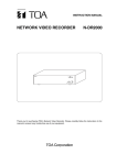
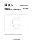
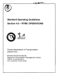
6. SYSTEM CONFIGURATION
The connection of a basic system is shown below.
The analog CCTV system is comprised of conventional cameras and switchers.
When using a PoE-compatible hub, the power supply need not be connected to the N-VT2010 Network Video
Transmitter, N-VR2010 Network Video Receiver and N-CC2360 Network Color camera. When using a hub not
supporting PoE, power must be independently supplied to each device. Connect the AC mains to N-DR2000
Network Video Recorder.
Connect 24V AC to the N-CC2564 Network Combination Dome Camera.
Network Video Transmitter
N-VT2010
Network Video Transmitter
N-VT2010
Analog
CCTV system
Combination Dome Camera
RS-485
To 24V AC
PoE compatible
switching HUB
Network Color Camera
N-CC2360
8
7
6
5
4
3
2
1
DC-IN
To AC mains
Network Combination
Dome Camera
N-CC2564
Software Decoder
N-SD2000
To 24V AC
Network Video Recorder
N-DR2000
TM
R
D
RO
ER
HD
W
PO
ER
Network Video Receiver
N-VR2010
Monitor
NETWORK V IDEO RECORDER N- DR2000
To AC mains
8
: Coaxial cable
: 10BASE-T/100BASE-TX
: 100BASE-TX/1000BASE-T
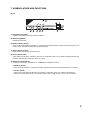
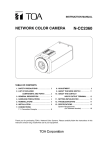
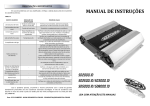
7. NOMENCLATURE AND FUNCTIONS
[Front]
10/100M PoE
1
2
3
4
5
6
(1) Initialization Key [INIT]
Initializes the setting contents to default conditions.
(2) Reset Key [RESET]
Restarts the Receiver.
(3) Ready Indicator (Green)
Lights continuously while the Receiver is operating. The indicator flashes quickly when the Receiver is set
to start mode, and flashes slowly during firmware update.
(4) Busy Indicator (Yellow)
Lights continuously during communications.
(5) Error Indicator (Red)
Lights when the Receiver's operation stops due to equipment failure. The indicator extinguishes when the
Receiver automatically resets and returns to normal.
(6) Network Terminal (RJ-45)
Connect this terminal to a 10BASE-T or 100BASE-TX compatible network.
• LINK/ACT (Green)
Lights when the network is correctly connected, and flashes while data is being transmitted or received
• FD/COL (Yellow)
Lights continuously while the Receiver is operating in full-duplex mode, and remains unlit while the
Receiver is in half-duplex mode. The indicator flashes when a data collision occurs over the network.
9
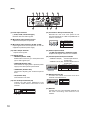
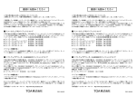
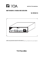
[Rear]
7
8
LINE
VOL
9
10
MIC IN
VIDEO
OUT
11
12
AUDIO ADJ.
NC
PHANTOM
MIC
12V
13
OUT
1
2
24V
IN
IN
ON
LINE
AUDIO
CONTACT
OUT
IN
OUT
1 2 C 1 2 C
MAX 0.2A
RS485
+
CONTACT
14
(7) Audio Input Terminal
(-10 dB, 10 kΩ, unbalanced type)
Receives line level audio signals.
15
RS485
RS-232C
16
17
(13) 24 V AC/24 V DC Input Terminal (3P)
Receives 24 V AC or 24 V DC power. Do not
use this terminal when a PoE-compatible hub is
used for connection.
(8) Microphone Input Volume Control
Adjusts the microphone input level.
(9) Microphone Input Terminal (-60 dB, 2.2 kΩ)
Inputs signals from the microphone. 9V can be
supplied for phantom power supply.
(10) Video Output Terminal
Outputs video signals.
(11) Setting switch
• MIC/LINE (default: LINE)
Selects either line level (7) or microphone level
(9) for audio signal input.
• PHANTOM (default: OFF)
Sets whether to supply the 9 V phantom power
supply to the microphone input terminal.
• AUDIO ADJ (default: OFF)
Used when adjusting the audio/microphone
level.
• NC (default: OFF)
This terminal is not used.
No.
1
2
1
2
3
3
(14) Audio Output Terminal
(-10 dB, low impedance, unbalanced type)
Outputs audio signals received via a network.
(15) Contact Input and Output Terminals
• CONTACT IN (3P) : Contact input terminal
(2 channels)
• CONTACT OUT (3P): Contact output terminal
(2 channels)
No.
Terminal name
No.
Terminal name
1
2
3
CONTACT IN 1
CONTACT IN 2
C
4
5
6
CONTACT OUT 1
CONTACT OUT 2
C
1 2 3 4 5 6
(16) RS-485 Terminal (3P)
Controls the remote controllers and other
external connected devices.
No.
(12) 12 V DC Output Terminal (2P)
Outputs 12 V DC power. (Maximum 0.2 A)
Connect TOA's remote controllers to this
terminal.
No.
1
2
1
10
2
Terminal name
12 V DC
GND
Terminal name
24 V AC/DC +
24 V AC/DC FG
7
8
9
Terminal name
RS-485 +
GND
RS-485 -
7 8 9
(17) RS-232C
Connect this port to the RS-232C terminal of a
PC when controlling other devices via a
network.
8. CONNECTIONS
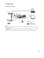
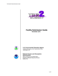
8.1. Connection example
PoE Compatible
Switching HUB
8
7
6
5
4
Software Decoder
N-SD2000
3
2
1
DC-IN
Network Video Receiver
N-VR2010
LINE
To AC mains
VOL
VIDEO
OUT
MIC IN
AUDIO ADJ.
NC
PHANTOM
MIC
12V
OUT
1
2
24V
IN
IN
LINE
AUDIO
CONTACT
CT
OUT
ON
IN
OUT
OU
1 2 C 1 2 C
Video input
MAX 0.2A
RS485
+
CONTACT
RS485
RS-232C
Video output
Monitor
Network Video Transmitter
N-VT2010
: BNC plug (optional)
Microphone
Color Camera
: Coaxial cable
: 10BASE-T/100BASE-TX
: 100BASE-TX/1000BASE-T
Notes
• Do not connect the 24 V AC or 24 V DC power when using a PoE-compatible hub since the power is
supplied from the hub.
• Connect the 24 V AC or 24 V DC power when not using a PoE-compatible hub since no power is supplied
from the hub.
• Shielded (STP) network cables must be used with this unit to ensure compliance with EMC standards.
11
8.2. Monitor connection
Connect the Receiver's video output terminal to the monitor's video input terminal using a coaxial cable (75Ω,
BNC).
8.3. Network Connection
Connect the Receiver to a hub using a straight cable. Use a null modem cable when connecting the Receiver
directly to a PC.
8.4. Microphone Connection
Connect a microphone using a mini-Jack.
When using an electret-condenser microphone, set the 9 V phantom power to ON.
8.5. Audio Input/Output connection
Connect line level audio signals using a pin jack. Audio input cannot be used simultaneously with microphone
input.
8.6. Contact Input and Output Terminals
Contact Input
There are two no-voltage contact inputs for connection of sensor trigger signals, etc. For details, refer to the
setup manual.
Contact Output
There are two contact outputs, allowing external connected device control and contact bridging between video
network system devices. For details, refer to the setup manual.
• Applicable cable
Solid cable:
Stranded cable:
AWG28 (Ø 0.32 mm) - AWG22 (Ø 0.65 mm)
AWG28 (0.08 mm2) - AWG22 (0.32 mm2)
Note
Strip the cable sheath approximately 10mm, then insert the cable while pushing down on the terminal button
with a screwdriver.
12
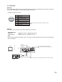
8.7. Serial Port
[RS-232C]
Use a null modem cable such as the YR-S2320 when connecting control terminals of the remote controller to
this terminal. No RS-232C connector plug is supplied with the unit.
• RS-232C Connector D-sub 9P
1 2 3 4 5
6 7 8 9
No.
1
2
3
4
5
6
7
8
9
Terminal name
Unconnected
RXD (Reception data)
TXD (Transmission data)
Unconnected
GND
Unconnected
RTS (Transmission request)
CTS (Transmission permission)
Unconnected
Both the RTS and CTS pins are internally shorted.
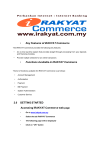
[RS-485]
Connect the control terminal of the remote controller to this terminal.
• Applicable cable
Solid cable:
Stranded cable:
AWG28 (Ø 0.32 mm) - AWG22 (Ø 0.65 mm)
AWG28 (0.08 mm2) - AWG22 (0.32 mm2)
Note
Strip the cable sheath approximately 10mm, then insert the cable while pushing down on the terminal button
with a screwdriver.
Network
Video Receiver
N-VR2010
Monitor
LINE
Rear
VOL
Connect the 24 V AC or 24 V DC
when not using a PoE-compatible hub.
VIDEO OUT
VIDEO
DE
OUT
UT
MIC IN
AUDIO ADJ.
NC
PHANTOM
MIC
12V
OUT
1
2
24V
IN
IN
LINE
AUDIO
CONTACT
OUT
IN
OUT
1 2 C 1 2 C
VIDEO IN
RS485
+
CONTACT
RS-485(+)
ON
RS485
RS-232C
RS-485(-)
RS-485
DC12 V
Remote Controller
C-RM500
Note: Connect the 12 V DC terminal when using a remote controller.
13
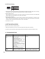
8.8. DIP Switch Setting
No.
1 2 3 4
1
2
3
4
Terminal name
MIC/ LINE
PHANTOM
AUDIO ADJ
NC
1: Selects either microphone level signal or line level signal as the audio input. Set to "MIC" when connecting
a microphone, and to "LINE" when connecting other devices. ("LINE" is the default.)
2: Supply voltage is 9 V DC.
When supplying the phantom power to the device connected to the audio input terminal, set the MIC/LINE
switch to MIC, then set this switch 2 to ON. ("OFF" is the default.)
3: Used for audio adjustment.
When adjusting, set this switch to ON and restart the Receiver. When the adjustment is complete, set this
switch to OFF and restart the Receiver. Audio signals from the audio input and microphone can be output
through the audio output terminal and monitored. ("OFF" is the default.)
4: This switch is not used.
9. SETTING INITIALIZATION
Returns the set contents to default conditions.
1. Either press the Reset key or switch on the power again while holding down the INIT key.
2. Continue to press the INIT key until the Ready indicator has switched from flashing to steady-on mode.
10. TROUBLESHOOTING
Symptom
Remedy
Possible Cause
Receiver does not start. Power is not supplied.
Supply power independently to the
(Ready LED does not [ When using a PoE-compatible hub Receiver.
for power supply ]
light.)
• Receiver not connected to the
PoE-compatible hub.
• PoE-compatible hub’s PoE
function is not made valid.
• Receiver is connected to the PoEcompatible hub’s port not
supporting PoE.
• Power requirement exceeds the
PoE-compatible hub’s supply
capability.
[ When using 24V AC or 24V DC for
power supply ]
• Incorrect terminal connections.
LINK/ACT LED does
not light.
14
Cable is not correctly connected to Confirm that the cable type (category, null
modem or straight) is appropriate for the
the Receiver’s network terminal.
connected port, then connect correctly.
11. SPECIFICATIONS
[N-VR2010 CU]
Power Source
Power Consumption
Power Terminal
Power Output
Video Output
Audio Input
Audio Output
Audio Frequency Response
Contact Input
Contact Output
Serial Port
Network
Network I/F
Network Protocol
Video Compression/Resolution
Frame Rate
Audio Compression/Decompression
Audio Sampling Frequency
Image Transfer Rate
Other Function
Operating Temperature
Operating Humidity
Finish
Dimensions
Weight
* 0 dB = 1V
24 V AC, 50/60 Hz or 24 V DC or PoE (IEEE802.3af)
10 W: at 24 V AC (9 W: PoE, 400 mA: 24 V DC)
Screwless connector (Solid cable: ø 0.4 – ø 1.2 mm (AWG 26 – 16)
Stranded cable: 0.3 – 1.25 mm2 (AWG 22 – 16))
12 V DC, max. 0.2 A, screwless connector
1 channel, VBS 1.0 V(p-p), 75 Ω, BNC jack, NTSC
1 channel, unbalanced, LINE/MIC changeable, volume adjustable
LINE: – 10 dB*, 10 kΩ, RCA pin jack
MIC: – 60 dB*, 2.2 kΩ, mini-jack, volume adjustable
phantom power supply (9 V, can be set with the switch)
1 channel, – 10 dB*, low impedance, unbalanced, RCA pin jack
50 to 14,000 Hz (when the sampling frequency is 32 kHz)
2 channel, no-voltage contact input, open voltage: 3 V DC,
short-circuit current : Under 10 mA, loop resistance: Under 200 Ω,
screwless connector
2 channel, open collector output, withstand voltage: 30 V DC,
control current: 50 mA, screwless connector
RS-232C: D-sub connector (9 pins, male), RS-485: screwless
connector
10BASE-T/100BASE-TX, Auto-Nego/Manual: RJ45 connector
TCP, UDP, SIP, RTP, IGMP, HTTP, ARP, DHCP, DNS, SNTP
MPEG-4: D1 (720 x 480), Half D1 (720 x 240), QVGA (320 x 240)
MPEG-4: D1 max. 30 fps
Sub-band ADPCM, PCM (non-compression)
8 kHz, 32 kHz
MPEG-4: max. 4 Mbps
Password authentication
0°C to +50°C (32°F to 122°F)
Under 90% RH (no condensation)
Case: Surface-treated steel plate, silver, paint
136 (W) x 44 (H) x 127.9 (D) mm (5.35" x 1.73" x 5.04")
700 g (1.54 lb)
Note: The design and specifications are subject to change without notice for improvement.
15
[N-VR2010 PL]
Power Source
Power Consumption
Power Terminal
Power Output
Video Output
Audio Input
Audio Output
Audio Frequency Response
Contact Input
Contact Output
Serial Port
Network
Network I/F
Network Protocol
Video Compression/Resolution
Frame Rate
Audio Compression/Decompression
Audio Sampling Frequency
Image Transfer Rate
Other Function
Operating Temperature
Operating Humidity
Finish
Dimensions
Weight
* 0 dB = 1V
24 V AC, 50/60 Hz or 24 V DC or PoE (IEEE802.3af)
10 W: at 24 V AC (9 W: PoE, 400 mA: 24 V DC)
Screwless connector (Solid cable: ø 0.4 – ø 1.2 mm (AWG 26 – 16)
Stranded cable: 0.3 – 1.25 mm2 (AWG 22 – 16))
12 V DC, max. 0.2 A, screwless connector
1 channel, VBS 1.0 V(p-p), 75 Ω, BNC jack, PAL
1 channel, unbalanced, LINE/MIC changeable, volume adjustable
LINE: – 10 dB*, 10 kΩ, RCA pin jack
MIC: – 60 dB*, 2.2 kΩ, mini-jack, volume adjustable
phantom power supply (9 V, can be set with the switch)
1 channel, – 10 dB*, low impedance, unbalanced, RCA pin jack
50 to 14,000 Hz (when the sampling frequency is 32 kHz)
2 channel, no-voltage contact input, open voltage: 3 V DC,
short-circuit current : Under 10 mA, loop resistance: Under 200 Ω,
screwless connector
2 channel, open collector output, withstand voltage: 30 V DC,
control current: 50 mA, screwless connector
RS-232C: D-sub connector (9 pins, male), RS-485: screwless
connector
10BASE-T/100BASE-TX, Auto-Nego/Manual: RJ45 connector
TCP, UDP, SIP, RTP, IGMP, HTTP, ARP, DHCP, DNS, SNTP
MPEG-4: D1 (720 x 576), Half D1 (720 x 288), CIF (352 x 288)
MPEG-4: D1 max. 25 fps
Sub-band ADPCM, PCM (non-compression)
8 kHz, 32 kHz
MPEG-4: max. 4 Mbps
Password authentication
0°C to +50°C (32°F to 122°F)
Under 90% RH (no condensation)
Case: Surface-treated steel plate, silver, paint
136 (W) x 44 (H) x 127.9 (D) mm (5.35" x 1.73" x 5.04")
700 g (1.54 lb)
Note: The design and specifications are subject to change without notice for improvement.
URL: http://www.toa.jp/
133-22-050-80