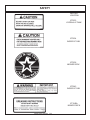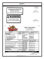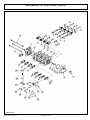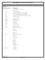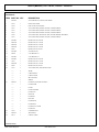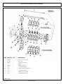
1
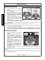
SABER
MOWER
NEW HOLLAND T6000
Current as of 06/17/2011
PARTS LISTING WITH
MOUNTING AND OPERATING
INSTRUCTIONS
Tiger Corporation
3301 N. Louise Ave.
Sioux Falls, SD 57107
1-800-843-6849
1-605-336-7900
www.tiger-mowers.com
06022005
TO THE OWNER / OPERATOR / DEALER
All implements with moving parts are potentially hazardous. There is no substitute for a cautious,
safe-minded operator who recognizes the potential hazards and follows reasonable safety practices.
The manufacturer has designed this implement to be used with all its safety equipment properly
attached to minimize the chance of accidents.
BEFORE YOU START!! Read the safety messages on the implement and shown in this manual.
Observe the rules of safety and use common sense!
READ AND UNDERSTAND THIS MANUAL! Non–English speaking operators will need to GET
THE MANUAL TRANSLATED as needed!
Warranty Information: Read and understand the complete Warranty Statement found in this manual. Fill out the
Warranty Registration form in full and return it within 90 days. Make certain the Serial Number of the machine is
recorded on the Warranty Card, and form that you retain.
FORWARD
This manual contains information about many features of the Tiger mowing
and roadside maintenance equipment. Some of these include: Safety precautions,
Assembly instructions, Operations, Maintenance and Parts. This manual will also
assist you in the proper break-in, daily care, and troubleshooting of your new
mower.
We recommend that you read carefully the entire manual before operating the
unit. Also, time spent in becoming fully acquainted with its performance features,
adjustments, and maintenance schedules will be repaid in a long and satisfactory
life of the equipment.
Troubleshooting - Please, before you call, help us to help you!
Please look at the equipment to observe what is happening, then:
• Classify the problem
• Hydraulic, electrical or mechanical - Read the trouble shooting section
• Tractor or Truck chassis - Contact vehicle dealer
• If unable to correct the problem yourself, contact your local Tiger Dealer after
gathering:
• Machine model _______________________
• Serial number ________________________
• Dealer name _________________________
• Detailed information about the problem including results of troubleshooting
Attention Owner / Operator / Dealer: It is your obligation to read, and understand,
the warranty information section located at the back of this manual denoting that the
purchaser understands the safety issues relating to this machine and has received
and will read a copy of this manual.
If at any time, you have a service problem with your Tiger mower, Contact
your local dealer for service and parts needed.
MANUFACTURED BY:
Tiger Corporation
3301 N. Louise Ave.
Sioux Falls, SD 57107
1-800-843-6849
1-605-336-7900
www.tiger-mowers.com
DISTRIBUTED BY:
_____________________
_____________________
1-_____-_____-________
1-_____-_____-________
TABLE OF CONTENTS
SAFETY SECTION_____________________________________
1
ASSEMBLY / MOUNTING SECTION______________________
2
OPERATION SECTION_________________________________
3
MAINTENANCE SECTION______________________________
4
PARTS SECTION______________________________________
5
COMMON PARTS SECTION____________________________
6
WARRANTY INFORMATION_____________________________
7
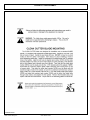
This symbol means:
CAUTION – YOUR SAFETY IS AT RISK!
When you see this symbol, read and
follow the associated instructions carefully
or personal injury or damage may result.
Tiger is a registered trademark.
SAFETY
SAFETY
SECTION
Saber Safety Section 1-1
SAFETY
General Safety Instructions and Practices
A safe and careful operator is the best operator. Safety is of primary importance to the
manufacturer and should be to the owner / operator. Most accidents can be avoided by being
aware of your equipment, your surroundings, and observing certain precautions. The first
section of this manual includes a list of Safety Messages that, if followed, will help protect the
operator and bystanders from injury or death. Read and understand these Safety Messages
before assembling, operating or servicing this mower. This equipment should only be
operated by those persons who have read the Manual, who are responsible and trained, and
who know how to do so safely and responsibly.
The Safety Alert Symbol combined with a Signal Word, as seen below, is used
throughout this manual and on decals which are attached to the equipment. The
Safety Alert Symbol means: “ATTENTION! BECOME ALERT! YOUR SAFETY IS
INVOLVED!” The symbol and signal word are intended to warn the owner /
operator of impending hazards and the degree of possible injury when operating
this equipment.
Practice all usual and customary safe working precautions and
above all -- remember safety is up to YOU! Only YOU can
prevent serious injury or death from unsafe practices.
Indicates an imminently hazardous situation that, if not avoided, WILL result in DEATH
OR VERY SERIOUS INJURY.
Indicates an imminently hazardous situation that, if not avoided, COULD result in
DEATH OR SERIOUS INJURY.
Indicates an imminently hazardous situation that, if not avoided, MAY result in MINOR
INJURY.
IMPORTANT!
NOTE:
Identifies special instructions or procedures that, if not strictly observed, could result
in damage to, or destruction of the machine, attachments or the enviroment.
Identifies points of particular interest for more efficient or convienient operation or
repair. (SG-1)
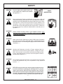
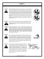
READ, UNDERSTAND, and FOLLOW the following Safety Messages.
Serious injury or death may occur unless care is taken to follow the
warnings and instructions stated in the Safety Messages. Always use
good common sense to avoid hazards. (SG-2)
Saber Safety Section 1-2
SAFETY
Si no lee Ingles, pida ayuda a alguien que
si lo lea para que le traduzca las medidas
de seguridad. (SG-3)
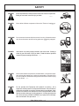
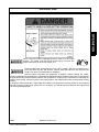
DANGER!
Never operate the Tractor or Implement until you have read and
completely understand this Manual, the Tractor Operator’s Manual,
and each of the Safety Messages found in the Manual or on the Tractor
and Implement. Learn how to stop the tractor engine suddenly in an
emergency. Never allow inexperienced or untrained personnel to
operate the Tractor and Implement without supervision. Make sure
the operator has fully read and understands the manuals prior to
operation. (SG-4)
WARNING!
LEA EL
INSTRUCTIVO!
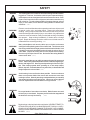
Always maintain the safety decals in good readable condition. If the
decals are missing, damaged, or unreadable, obtain and install replacement decals immediately. (SG-5)
WARNING!
Make certain that the “Slow Moving Vehicle” (SMV) sign is installed in
such a way as to be clearly visible and legible. When transporting the
Equipment use the Tractor flashing warning lights and follow all local traffic
regulations. (SG-6)
WARNING!
Operate this Equipment only with a Tractor equipped with an
approved roll-over-protective system (ROPS). Always wear seat
belts. Serious injury or even death could result from falling off the
tractor--particularly during a turnover when the operator could be
pinned under the ROPS. (SG-7)
WARNING!
Do not modify or alter this Implement. Do not permit anyone to modify
or alter this Implement, any of its components or any Implement
function. (SG-8)
DANGER!
BEFORE leaving the tractor seat, always engage the brake and/or set
the tractor transmission in parking gear, disengage the PTO, stop the
engine, remove the key, and wait for all moving parts to stop. Place the
tractor shift lever into a low range or parking gear to prevent the tractor
from rolling. Never dismount a Tractor that is moving or while the engine
is running. Operate the Tractor controls from the tractor seat only.
(SG-9)
Saber Safety Section 1-3
!
PELIGRO!
SAFETY
DANGER!
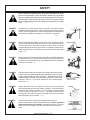
Never allow children or other persons to ride on the Tractor or Implement.
Falling off can result in serious injury or death.
(SG-10)
DANGER!
Never allow children to operate or ride on the Tractor or Implement.
(SG-11)
WARNING!
Do not mount the tractor while the tractor is moving. Mount the tractor
only when the tractor and all moving parts are completely stopped.
(SG-12)
DANGER!
Start tractor only when properly seated in the tractor seat. Starting a
tractor in gear can result in injury or death. Read the tractor operators
manual for proper starting instructions. (SG-13)
DANGER!
Never work under the Implement, the framework, or any lifted component unless the Implement is securely supported or blocked up to
prevent sudden or inadvertent falling which could cause serious injury
or even death. (SG-14)
DANGER!
Do not operate this Equipment with hydraulic oil leaking. Oil is
expensive and its presence could present a hazard. Do not check for
leaks with your hand! Use a piece of heavy paper or cardboard. Highpressure oil streams from breaks in the line could penetrate the skin
and cause tissue damage including gangrene. If oil does penetrate the
skin, have the injury treated immediately by a physician knowledgeable and skilled in this procedure. (SG-15)
Saber Safety Section 1-4
SAFETY
WARNING!
The operator and all support personnel should wear hard hats,
safety shoes, safety glasses, and proper hearing protection at all
times for protection from injury including injury from items thrown by
the equipment.
(SG-16)
CAUTION!
PROLONGED EXPOSURE TO LOUD NOISE MAY CAUSE PERMANENT HEARING LOSS! Tractors with or without an Implement attached can often be noisy enough to cause permanent hearing loss.
We recommend that you always wear hearing protection if the noise in
the operator’s position exceeds 80db. Noise over 85db over an extended period of time will cause severe hearing loss. Noise over 90db
adjacent to the operator over an extended period of time will cause
permanent or total hearing loss. Note: Hearing loss from loud noise
[from tractors, chain saws, radios, and other such sources close to the
ear] is cumulative over a lifetime without hope of natural recovery. (SG-I7)
WARNING!
Transport only at safe speeds. Serious accidents and injuries
can result from operating this equipment at unsafe speeds.
Understand the Tractor and Implement and how it handles before
transporting on streets and highways. Make sure the Tractor
steering and brakes are in good condition and operate properly.
Before transporting the Tractor and Implement, determine
the safe transport speeds for you and the equipment. Make
sure you abide by the following rules:
1. Test the tractor at a slow speed and increase the speed slowly.
Apply the brakes smoothly to determine the stopping characteristics
of the Tractor and Implement. As you increase the speed of the
Tractor the stopping distance increases. Determine the maximum
safe transport speed for you and this equipment.
2. Test the equipment at a slow speed in turns. Increase the speed
through the turn only after you determine that it is safe to operate
at a higher speed. Use extreme care and reduce your speed
when turning sharply to prevent the tractor and implement from
turning over. Determine the maximum safe turning speed for you
and this equipment before operating on roads or uneven ground.
3. Only transport the Tractor and Implement at the speeds that you
have determined are safe and which allow you to properly
control the equipment.
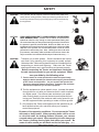
Be aware of the operating conditions. Do not operate the Tractor
with weak or faulty brakes. When operating down a hill or on wet
or rain slick roads, the braking distance increases: use extreme
care and reduce your speed. When operating in traffic always use
the Tractor’s flashing warning lights and reduce your speed. Be
aware of traffic around you and watch out for the other guy. (SG-19)
Saber Safety Section 1-5
SAFETY
WARNING!
Never attempt to lubricate, adjust, or remove material from the
Implement while it is in motion or while tractor engine is running. Make
sure the tractor engine is OFF before working on the Implement.
(SG-20)
WARNING!
Periodically inspect all moving parts for wear and replace when
necessary with authorized service parts. Look for loose fasteners,
worn or broken parts, and leaky or loose fittings. Make sure all pins
are properly secured. Serious injury may occur from not maintaining
this machine in good working order. (SG-21)
WARNING!
Always read carefully and comply fully with the manufacturers instructions when handling oil, solvents, cleansers, and any other chemical
agent. (SG-22)
DANGER!
Never run the tractor engine in a closed building or without adequate
ventilation. The exhaust fumes can be hazardous to your health.
(SG-23)
DANGER!
KEEP AWAY FROM ROTATING ELEMENTS to prevent entanglement
and possible serious injury or death.
(SG-24)
DANGER!
Never allow children to play on or around Tractor or Implement. Children
can slip or fall off the Equipment and be injured or killed. Children can
cause the Implement to shift or fall crushing themselves or others. (SG-25)
Saber Safety Section 1-6
SAFETY
DANGER!
NEVER use drugs or alcohol immediately before or while operating the
Tractor and Implement. Drugs and alcohol will affect an operator’s
alertness and coordination and therefore affect the operator’s ability to
operate the equipment safely. Before operating the Tractor or Implement, an operator on prescription or over-the-counter medication must
consult a medical professional regarding any side effects of the medication that would hinder their ability to operate the Equipment safely.
NEVER knowingly allow anyone to operate this equipment when their
alertness or coordination is impaired. Serious injury or death to the
operator or others could result if the operator is under the influence of
drugs or alcohol. (SG-27)
DANGER!
Operate the Tractor and/or Implement controls only while properly seated
in the Tractor seat with the seat belt securely fastened around you.
Inadvertent movement of the Tractor or Implement may cause serious
injury or death. (SG-29)
WARNING!
Mow only in conditions where you have clear visibility in daylight or with
adequate artificial lighting. Never mow in darkness or foggy conditions
where you cannot clearly see at least 100 yards in front and to the sides of
the tractor and mower. Make sure that you can clearly see and identify
passersby, steep slopes, ditches, drop-offs, overhead obstructions, power
lines, debris and foreign objects. If you are unable to clearly see this type
of items discontinue mowing.
(SGM-1)
DANGER!
There are obvious and hidden potential hazards in the operation of this
Mower. REMEMBER! This machine is often operated in heavy brush
and in heavy weeds. The Blades of this Mower can throw objects if
shields are not properly installed and maintained. Serious injury or
even death may occur unless care is taken to insure the safety of the
operator, bystanders, or passersby in the area. Do not operate this
machine with anyone in the immediate area. Stop mowing if anyone
is within 100 yards of mower. (SGM-2)
DANGER!
All Safety Shields, Guards and Safety devices including
(but not limited to) - the Deflectors, Chain Guards, Steel
Guards, Gearbox Shields, PTO integral shields , and
Retractable Door Shields should be used and maintained in good working condition. All safety devices
should be inspected carefully at least daily for missing
or broken components. Missing, broken, or worn items
must be replaced at once to reduce the possibility of
injury or death from thrown objects, entanglement, or
blade contact. (SGM-3)
Saber Safety Section 1-7
SAFETY
DANGER!
WARNING!
WARNING!
WARNING!
WARNING!
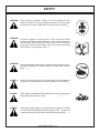
The rotating parts of this machine have been designed and tested for
rugged use. However, the blades could fail upon impact with heavy,
solid objects such as metal guard rails and concrete structures. Such
impact could cause the broken objects to be thrown outward at very
high velocities. To reduce the possibility of property damage, serious
injury, or even death, never allow the cutting blades to contact such
obstacles. (SGM-4)
Extreme care should be taken when operating near loose objects such
as gravel, rocks, wire, and other debris. Inspect the area before
mowing. Foreign objects should be removed from the site to prevent
machine damage and/or bodily injury or even death. Any objects that
cannot be removed must be clearly marked and carefully avoided by
the operator. Stop mowing immediately if blades strike a foreign
object. Repair all damage and make certain rotor or blade carrier is
balanced before resuming mowing. (SGM-5)
Many varied objects, such as wire, cable, rope, or chains, can become
entangled in the operating parts of the mower head. These items could
then swing outside the housing at greater velocities than the blades. Such
a situation is extremely hazardous and could result in serious injury or
even death. Inspect the cutting area for such objects before mowing.
Remove any like object from the site. Never allow the cutting blades to
contact such items. (SGM-6)
Mow at the speed that you can safely operate and control the tractor and
mower. Safe mowing speed depends on terrain condition and grass type,
density, and height of cut. Normal ground speed range is from 0 to 5 mph.
Use slow mowing speeds when operating on or near steep slopes,
ditches, drop-offs, overhead obstructions, power lines, or when debris and
foreign objects are to be avoided. (SGM-7)
Avoid mowing in reverse direction when possible. Check to make sure
there are no persons behind the mower and use extreme care when
mowing in reverse. Mow only at a slow ground speed where you can safely
operate and control the tractor and mower. Never mow an area that you
have not inspected and removed debris or foreign material. (SGM-8)
WARNING!
Do not put hands or feet under mower decks. Blade Contact can result
serious injury or even death. Stay away until all motion has stopped and
the decks are securely blocked up.
(SGM-9)
DANGER!
Replace bent or broken blade with new blades. NEVER ATTEMPT TO
STRAIGHTEN OR WELD ON BLADES SINCE THIS WILL LIKELY
CRACK OR OTHERWISE DAMAGE THE BLADE WITH SUBSEQUENT FAILURE AND POSSIBLE SERIOUS INJURY FROM THROWN
BLADES. (SGM-10)
Saber Safety Section 1-8
SAFETY
WARNING!
Do not mow with two machines in the same area except with Cab tractors
with the windows closed. (SGM-11)
DANGER!
Rotary and Flail Mowers are capable under adverse conditions of
throwing objects for great distances (100 yards or more) and causing
serious injury or death. Follow safety messages carefully.
STOP MOWING IF PASSERSBY ARE WITHIN 100 YARDS UNLESS:
-Front and Rear Deflectors are installed and in good,
working condition;
-Mower Head is running close to and parallel to the ground
without exposed Blades;
-Passersby are outside the existing thrown-object zone;
-All areas have been thoroughly inspected and all foreign
material such as rocks, cans, glass, and general debris
has been removed.
NOTE: Where there are grass and weeds high enough to hide debris
that could be struck by the blades, the area should be: inspected and large debris removed, mowed at an intermediate
height, inspected closely with any remaining debris being removed, and mowed again at desired final height. (SBM-1)
DANGER!
Use extreme caution when raising the Mower head. Stop the Blades
from turning when the Mower Head is raised and passersby are within
100 yards. Raising the Mower head exposes the Cutting Blades
which creates a potentially serious hazard and can cause serious
injury by objects thrown from the Blades or by contact with the Blades.
(SBM-2)
DANGER!
Be particularly careful in transport. The Mower has raised the center
of gravity for the tractor and has increased the possibility of overturn. Turn
curves or go up slopes only at low speed and using a gradual turning
angle. Slow down on rough or uneven surfaces. (SBM-3)
WARNING!
Never Leave the mower unattended while the head is in the
raised position. The mower could fall causing serious injury
to anyone who might inadvertently be under the mower.
(SBM-4)
WARNING!
The rotating parts of this machine continue to rotate even after the Tractor
has been turned off. The operator should remain in his seat for 60
seconds after the brake has been set, the PTO disengaged, the tractor
turned off, and all evidence of rotation has ceased. (SBM-5)
“Wait a minute...Save a life!”
Saber Safety Section 1-9
SAFETY
Relieve hydraulic pressure prior to doing any maintenance or repair
work on the Implement. Place the Mower Head on the ground or
securely supported on blocks or stands, disengage the PTO, and turn
off the engine. Push and pull the control Levers or Joystick several
times to relieve pressure prior to starting any maintenance or repair
work.
(SBM-6)
DANGER!
Always keep a careful lookout and use extreme care when working
around overhead obstructions. Never allow the Mower head or boom
within 10 feet of any power line. When working close to overhead power
lines consult your electric company for a safe code of operation.
(SBM-7)
DANGER!
When transporting Boom Mower on a truck or trailer, the height or width
may exceed legal limits when the boom is in the transport position.
Contact with side or overhead structures or power lines can cause
property damage or serious injury or death. If necessary lower boom to
reduce height and/or remove mowing head to reduce width to the legal
limits. (SBM-8)
DANGER!
Never operate the Tractor and Mower Unit without an OPS (Operators
Protective Structure) or Cab to prevent injury from objects thrown from
ground or from overhead trimming. Stop mowing if workers or passersby
are with in 100 yards. (SBM-9)
DANGER!
Left Rear Wheel must have a minimum of 1500 pound contact with the
surface to prevent lateral instability and possible tip-over which could
result in serious bodily injury or even death. Widen the wheel tread
and add weights if needed. Refer to the mounting instructions or call
Customer Service if you need assistance with Counterweight
Procedure. (SBM-11)
DANGER!
Always disconnect the wire leads from the mower pump solenoid
before performing service on the Tractor or Mower. Use caution when
working on the Tractor or Mower. Tractor engine must be stopped
before working on Mower or Tractor. The Mower Blades could
inadvertently be turned on without warning and cause immediate
dismemberment, injury or death. (SBM-12a)
DANGER!
The flail cutter shaft is designed for standard rotation (same
rotation as the tractor wheels during forward travel). Never operate the
cutter shaft in the reverse rotation. Operating this mower in reverse
rotation may cause objects to be thrown out the front of the mower
head.
Saber Safety Section 1-10
SAFETY
WARNING!
Engine Exhaust, some of its constituents, and certain components contain or emit
chemicals known to the state of California to cause cancer and birth or other reproductive
harm.
WARNING!
Battery posts, terminals and related accessories contain lead and lead compounds,
chemicals known to the state of California to cause cancer and birth or other reproductive
harm. Wash hands after handling!
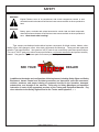
Tiger mowers use balanced and matched system components for blade carriers, blades, cuttershafts, knives, knife hangers, rollers, drive-train components and bearings. These parts are made and
tested to Tiger specifications. Non-genuine “will fit” parts do not consistently meet these specifications.
The use of “will fit” parts may reduce mower performance, void mower warranties and present a safety
hazard. Use genuine Tiger mower parts for economy and safety.
SEE YOUR
DEALER
In addition to the design and configuration of this Implement, including Safety Signs and Safety
Equipment, hazard control and accident prevention are dependent upon the awareness,
concern, prudence, and proper training of personnel involved in the operation, transport,
maintenance, and storage of the machine. Refer also to Safety Messages and operation
instruction in each of the appropriate sections of the Tractor and Equipment Manuals. Pay
close attention to the Safety Signs affixed to the Tractor and Equipment. (SG-18)
Saber Safety Section 1-11
SAFETY
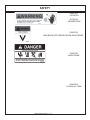
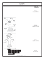
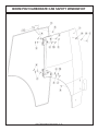
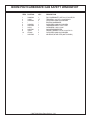
PART NO.
LOCATION
002369
HYDRAULIC TANK
00725746
INSIDE OF CAB
00769737
MOWER DECK
Saber Safety Section 1-12
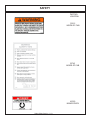
SAFETY
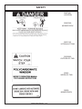
PART NO.
LOCATION
00758194
MOWER DECK
02962764
MAIN BOOM, SECONDARY BOOM, MAIN FRAME
02962765
MAIN FRAME
02965262
HYDRAULIC TANK
Saber Safety Section 1-13
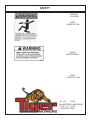
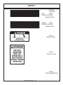
SAFETY
PART NO.
LOCATION
02967668
MOWER DECK
02971123
HYDRAULIC TANK
03200285
OUTSIDE OF CAB
22645
INSIDE OF CAB
22839
MOWER DECK
Saber Safety Section 1-14
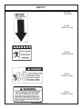
SAFETY
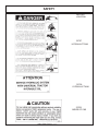
PART NO.
LOCATION
22840
INSIDE OF CAB
24028
MOWER DECK
25387
INSIDE OF CAB
10” x 5.5”
31522
MOWER DECK, MAIN BOOM
18.25” x 10” 31523
HYDRAULIC TANK
Saber Safety Section 1-15
SAFETY
PART NO.
LOCATION
32428
MAIN BOOM
32449
HYDRAULIC TANK
Saber Safety Section 1-16
SAFETY
PART NO.
LOCATION
32707
HYDRAULIC TANK
32708
HYDRAULIC TANK
32709
INSIDE OF CAB
Saber Safety Section 1-17
SAFETY
PART NO.
LOCATION
33224
MOWER DECK
33302
INSIDE OF CAB
35284
INSIDE OF CAB
33438
MAIN BOOM
Saber Safety Section 1-18
SAFETY
PART NO.
LOCATION
33512
INSIDE OF CAB
33743
INSIDE OF CAB
42350
MOWER DECK
Saber Safety Section 1-19
SAFETY
PART NO.
LOCATION
RED
42399
REFLECTIVE TAPE
MOWER DECK
AMBER
42400
REFLECTIVE TAPE
MOWER DECK
6T3217
MOWER DECK
6T3219
INSIDE OF CAB
6T3220
FRONT PUMP MOUNT
Saber Safety Section 1-20
SAFETY
PART NO.
LOCATION
6T3222
INSIDE OF CAB
6T3224
MOWER DECK
6T3225
INSIDE OF CAB
6T3230
INSIDE OF CAB
Saber Safety Section 1-21
SAFETY
PART NO.
LOCATION
6T3233
HYDRAULIC TANK
6T3234
INSIDE OF CAB
6T3236
MOWER DECK
6T3243
INSIDE OF CAB
6T3249A
MOWER DECK
Saber Safety Section 1-22
SAFETY
PART NO.
LOCATION
6T3261
MOWER DECK
TB1011
MOWER DECK
34852
HYDRAULIC TANK
Saber Safety Section 1-23
SAFETY
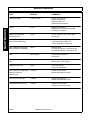
ITEM
PART NO.
QTY.
DESCRIPTION
1
50023
00776031
33997
AVAIL
1
1
*
*
*
AVAIL
1
1
1
4
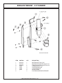
MANUAL CANISTER COMPLETE
ROUND MANUAL CANISTER
DECAL, SHEET, MANUAL CANISTER
DECAL
DECAL
DECAL
SPECIFIC PRODUCT MANUAL
E M I SAFETY MANUAL
FRONT ADHESIVE PAD
REAR ADHESIVE PAD
ZIP TIE 14” LONG
2
3
4
5
6
7
8
9
*
33753
34296
34297
6T1823
NOTE:
The manual canister can be bolted, zip tied or adhered to a variety of
surfaces. Locate a protected area within the view of the operator. Then
select an installation method and attach the canister. CAUTION - AVOID
DRILLING HOLES INTO UNKNOWN AREAS, wires and other parts may
be located behind these areas. When adhering the canister to a surface,
thoroughly clean that surface before installing the canister.
Saber Safety Section 1-24
SAFETY
FEDERAL LAWS AND REGULATIONS
This section is intended to explain in broad terms the concept and effect of federal laws and regulations
concerning employer and employee equipment operators. This section is not intended as a legal
interpretation of the law and should not be considered as such.
Employer-Employee Operator Regulations
U.S. Public Law 91-596 (The Williams-Steiger Occupational and Health Act of 1970) OSHA
This Act Seeks:
“...to assure so far as possible every working man and woman in the nation safe and
healthful working conditions and to preserve our human resources...”
DUTIES
Sec. 5 (a) Each employer(1) shall furnish to each of his employees employment and a place of employment which
are free from recognized hazards that are causing or are likely to cause death or serious
physical harm to his employees;
(2) shall comply with occupational safety and health standards promulgated under this
Act.
(b) Each employee shall comply with occupational safety and health standards and all
rules,
regulations and orders issued pursuant to this Act which are applicable to his
own actions
and conduct.
OSHA Regulations
OSHA regulations state in part: “At the time of initial assignment and at least annually
thereafter, the employer shall instruct every employee in the safe operation and servicing
of all equipment with which the employee is, or will be involved.”
Employer Responsibilities:
To ensure employee safety during Tractor and Implement operation, it is the employer’s responsibility
to:
1. Train the employee in the proper and safe operation of the Tractor and Implement.
2. Require that the employee read and fully understand the Tractor and Implement Operator’s manual.
3. Permit only qualified and properly trained employees to operate the Tractor and Implement.
4. Maintain the Tractor and Implement in a safe operational condition and maintain all shields and
guards on the equipment.
5. Ensure the Tractor is equipped with a functional ROPS and seat belt and require that the employee
operator securely fasten the safety belt and operate with the ROPS in the raised position at all
times.
6. Forbid the employee operator to carry additional riders on the Tractor or Implement.
7. Provide the required tools to maintain the Tractor and Implement in a good safe working condition
and provide the necessary support devices to secure the equipment safely while performing repairs
and service.
Child Labor Under 16 Years of Age
Some regulations specify that no one under the age of 16 may operate power machinery. It is your
responsibility to know what these regulations are in your own area or situation. (Refer to U.S. Dept. of
Labor, Employment Standard Administration, Wage & Home Division, Child Labor Bulletin #102.)
Saber Safety Section 1-25
SAFETY
Saber Safety Section 1-26
ASSEMBLY
SECTION
Assembly Section 2-1
ASSEMBLY
Before attempting to mount or service your Tiger mower, it is important to
read and understand all of the information in the Safety section of this manual.
Check complete shipment list against the packing list to make sure there are no
shortages. Make certain the tractor model is the appropriate one for the mower
received!
Use a floor jack, hoist or fork lift to lift or raise heavy parts whenever
possible whether mentioned or not.
Read and understand the entire assembly section instructions before attempting
to mount your Tiger mower. Refer to the parts section of this manual for detailed
illustrations to locate all parts.
TRACTOR PREPARATION
A: Remove right and left hand steps.
B: Disconnect battery cables from both batteries.
C: Remove the lower battery and it’s tray.
D: Remove engine side panels, or raise hood to access front pulley.
E: Remove plugs from tractor casting where main frame and pump
mount will be attached.
F: Remove any front weights and weight supports.
ADJUSTING REAR WHEELS
Raise rear of tractor onto jack-stands. Follow the instructions in the tractor
owners manual for adjusting tires and rims. The back wheels MUST be adjusted
to the widest setting. NOTE: This may require switching the wheels to opposite
sides of tractor. Also take note of any width restrictions when transporting by trailer.
(For ease of installation, it is best to leave the rear wheels removed during installation
of the mower.)
CRANKSHAFT ADAPTER
If necessary remove the four cap-screws from the crankshaft pulley. Then install
the crankshaft adapter and spacer to the pulley with cap-screws and lock-washers
as shown in the parts section.
T6000 Saber Assembly Section 2-2
ASSEMBLY
JOYSTICK MOUNT STAND
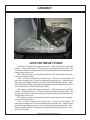
Place the front edge of the support bracket 2 ¾” back from the lower right front
window. Rotate stand to be 2 ¼” from the right door frame as shown below. Be
sure that the location of the stand will allow clearance between the joystick and all
existing interior levers, etc.
Drill 3 holes to match control bracket and secure with cap-screws and nylock
nuts noted in parts section.
Cut a 2 ¼” hole in the floor from inside the cab. This hole is to be located 2 1/2”
away from the edge, and 4” from the metal edge by the right door. Install trim lock
around the metal edges of the hole, then route the cables through the hole. Next,
wrap the cables with the 6” split hose at the point they pass through the hole, and
secure with zip-ties.JOYSTICK MOUNT STAND
Place the front edge of the support bracket 2 ¾” back from the lower right front
window. Rotate stand to be 2 ¼” from the right door frame as shown below. Be
sure that the location of the stand will allow clearance between the joystick and all
existing interior levers, etc.
Drill 3 holes to match control bracket and secure with cap-screws and nylock
nuts noted in parts section.
Cut a 2 ¼” hole in the floor from inside the cab. This hole is to be located 2 1/2”
away from the edge, and 4” from the metal edge by the right door. Install trim lock
around the metal edges of the hole, then route the cables through the hole. Next,
wrap the cables with the 6” split hose at the point they pass through the hole, and
secure with zip-ties.
T6000 Saber Assembly Section 2-3
ASSEMBLY
SWITCH BOX MOUNTING (JOYSTICK)
Locate the 2 holes in the right front corner of the cab frame. These will be the
mounting holes for the 2 mounting bolts of the switch box bracket. Mount the bracket
using the hardware supplied, as noted in the parts section.
SWITCH BOX WIRING
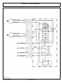
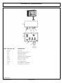
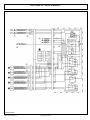
Refer to the Parts section for wiring diagrams. Remove top instrument panel
(tach, and hour meter) for access to the wires.
Route the red and green wire from the switch box wires from the switch box to
the bottom right corner of the instrumentm panel near window. Connect the red wire
to the white wire. (hot when key in on position)
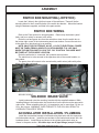
NOTE ONLY FOR ELECTRONIC VALVE: +12 VOLTS ELECTRICAL POWER
MUST BE TAKEN FROM A SOURCE LOCATION WHERE IT IS LIVE ONLY
WHEN THE IGNITION SWITCH IS IN THE “ON” POSITION. THIS WIRE MUST
BE FUSED AT THE SOURCE LOCATION.
Route the white wire to connected the hydraulic solenoid valve.
The switch box is to be secured to the operators side of the control handles, or
valve stand.
The green wires will connect to the neutral safety switch wires (white with yellow
stripe), under the cowl panel.
BEFORE WIRING
AFTER WIRING
SOLENOID BRAKE VALVE
Install a solenoid valve the mounting bracket with the supplied hardware. While
installing fittings to the brake valve, the electrical coil on the spool must be removed to
make room. When reinstalling the coil, it is important to use no more than 5 ft. lbs. (or
60 in. lbs.) torque. WARNING: OVER TORQUE TO THE COIL WILL RESULT IN
HYDRAULIC FAILURE OF SPOOL.
ACCUMULATOR INSTALLATION / PLUMBING
Install the accumulator bracket on left hand valve plate holes with the capscrews
and lockwashers shown. Install the accumulator in the bracket and secure with the
hardware shown. Install fittings and hoses to the cylinder and control valve as
shown in the parts section. Use teflon tape on all pipe fittings (except O-rings).
T6000 Saber Assembly Section 2-4
ASSEMBLY
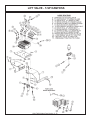
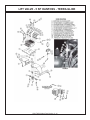
LIFT VALVE MOUNT
Install the valve mounting bracket to the inside of the right and left rear fender
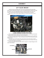
frame tube as shown below. Align the valve mounting plate with the drilled holes. Mark
the center of one of the holes above and in line with the slotted holes in the valve
plate. Do not use any holes that will be used to mount the valve on the plate.
Mount the lift valve with the supplied hardware. Refer the parts section for the
details.
LOAD SENSE HOSE ROUTING
The lift valve uses the Pressure, Return and Load Sense on the tractors rear remotes.
The ports used are directly under the valve mounting plate.
The pressure hose is routed from the tractor remotes to the inlet port of the HP Filter
on the valve mounting bracket. Then, the outlet port of the HP Filter to the pressure port
on the lift valve.
The return hose runs from the return port of the lift valve to the tractor remotes.
The load sense line is routed from the load sense port of the lift valve to the load
sense port on the tractor rear remotes.
For more information refer to the Parts Section pages for a complete diagram of the
tractor valve hookup.
LOAD SENSE
RETURN
PRESSURE
T6000 Saber Assembly Section 2-5
ASSEMBLY
4 CYLINDER EXHAUST MOUNT
NOTE: This should be done after mounting the main frame.
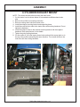
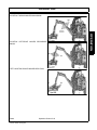
1. Cut the tractor hood as shown in pic. # 1 to accomodate modified exhaust turbo
tube.
2 Remove the muffler from existing turbo tube.
3. Remove existing turbo tube from tractor turbo.
4. Install the exhaust mounting bracket and supporting brace.
5. Cut the existing tube at turbo end 4-3/8” from hole center as shown in pic. # 2
and 3. Discard remaining portion of existing tube.
6. Install the turbo end of existing tube to the tractor turbo.
7. Connect the supplied tube to the turbo end of existing tube using the sealing
clamp as shown in pic. # 4. Do not tighten the hardware.
8. Install the exhaust clamp to the exhaust mounting bracket with the supplied
hardware. Refer parts section for the details.
9. Tighten the turbo existing hardware first and then the rest of the hardware.
10. Cut the muffler sweep off at the top and replace with a raincap, if necessary for
shipping, as shown in pic. # 5. Then install muffler to the turbo tube with the
existing hardware.
Picture # 1
Picture # 2
Picture # 3
T6000 Saber Assembly Section 2-6
ASSEMBLY
Picture # 4
Picture # 5
T6000 Saber Assembly Section 2-7
ASSEMBLY
6 CYLINDER EXHAUST MOUNT
NOTE: This should be done after mounting the main frame.
1. Cut the tractor hood as shown below to accomodate modified exhaust turbo
tube.
2 Remove the muffler from existing turbo tube.
3. Remove existing turbo tube from tractor turbo.
4. Install the exhaust mounting bracket and supporting brace.
5. Install the modified turbo tube to the tractor turbo with existing hardware. Do not
tighten the hardware.
6. Install the exhaust clamp to the exhaust mounting bracket with the supplied
hardware. Refer parts section for the details.
7. Tighten the turbo existing hardware.
8. Cut the muffler 8” off at the top as shown below and weld the sweep back on to
the top of the muffler maintaining the same direction. Then install muffler to the
turbo tube with the existing hardware.
T6000 Saber Assembly Section 2-8
ASSEMBLY
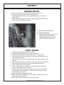
MIRROR MOUNT
1. Remove the existing mirror bracket and mirror from the cab.
2 Remove the mirror and knob from existing bracket.
3. Install the supplied bracket (using supplied hardware) on the cab as
shown below.
4. Install the mirror with the knob on the supplied bracket as shown below.
Refer to the Parts section for details.
A. Mirror/Light Mount Bracket
B. Existing Hardware
C. Distance the muffler screen is cut
back to fit the exhaust collar.
- Half distance from the top bolt
hole to the top of the screen.
LIGHT MOUNT
1.
2
3.
4.
Remove light and light bracket from hand rail.
Tape light back against the hand rail next to the cab.
At the base of the hand rail, cut through the rail 2” from the cab.
To disconnect the wiring for the light, cut the hand rail through the hole
where the wires extend.
5. On the cab ceiling, remove the speaker grill cover that is closest to the
hand rail.
6. Remove the plate inside the speaker cavity to reach the wire connectors.
7. Disconnect green connector and pull wire through the hand rail.
8. Then cut hand rail 2” from the frame.
9. Place a small amount of adhesive on outer edge of the lower hand
rail stub. Slide rubber cap on the stub.
10. Take second rubber cap and cut a small “X” at the end. Feed the light
wire through the cap, the hand rail, and back into the speaker cavity.
Re-attach green connector.
11. Attach the plate and speaker grill cover.
12. Place small amount of adhesive on outer edge of upper hand rail stub.
Slide rubber cap on the stub.
13. Mount light to mirror bracket as seen in Parts section.
T6000 Saber Assembly Section 2-9
ASSEMBLY
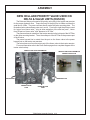
NEW HOLLAND PRIORITY VALVE USED ON
DELTA & VALUE UNITS (HUSCO)
The Delta and Value units need a NH priority valve plug in the tractor rear remotes
for the proper hydraulic flow. Torque the body fo the plug first to 94Nm and then the
small end to 15Nm. The ports used are directly under the valve mounting plate. The
illustration below shows these ports are in a row. From left to right the ports are used
for “return from Husco valve”, “plug to allow activation of the next two ports”, “return
from PB port on Husco valve” and “pressure to HP filter”.
The pressure hose is routed from the tractor remotes to the inlet port of the HP Filter
on the valve mounting bracket. Then, the outlet port of the HP Filter to the pressure port
of the lift valve.
The power beyond line is routed from the port on the Husco valve to the power
beyond port on the tractor rear remotes.
The return hose runs from the return port of the Husco valve to the tractor remotes.
For more information refer to the Parts Section pages for a complete diagram of the
tractor valve hookup.
NEW HOLLAND TRACTOR REMOTES
NEW HOLLAND TRACTOR REMOTE
PRIORITY VALVE PLUG
PRESSURE PORT
RETURN PORT
PRIORITY VALVE
PLUG
POWER BEYOND
PORT
T6000 Saber Assembly Section 2-10
ASSEMBLY
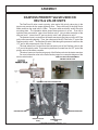
DANFOSS PRIORITY VALVE USED ON
DELTA & VALUE UNITS
The DanFoss lift valve needs a priority valve and a NH priority valve plug in the
tractor rear remotes for the proper hydraulic flow. Torque the body fo the plug first to
94Nm and then the small end to 15Nm. The ports used are directly under the valve
mounting plate. The illustration below shows these ports are in a row. From left to
right the ports are used for “return from Danfoss valve”, “plug to allow activation of the
next two ports”, “return from EF port on priority valve” and “pressure to valve”.
The pressure hose is routed from the tractor remotes to the inlet port of the HP Filter
on the valve mounting bracket. Then, the outlet port of the HP Filter to the “P” port of the
Danfoss priority valve. The Danfoss lift valve is fed through the pressure hose from the
“CF” port to the pressure port of the lift valve.
The load sense line is routed from the load sense port of the Danfoss valve to the
“LS” port of the priority valve. The power beyond hose is routed from the “EF” port of the
priority valve to the tractor remotes.
The return hose runs from the return port of the Danfoss valve to the tractor remotes.
For more information refer to the Parts Section pages for a complete diagram of the
tractor valve hookup.
NEW HOLLAND TRACTOR REMOTE
PRIORITY VALVE PLUG
NEW HOLLAND TRACTOR REMOTES
RETURN PORT
PRESSURE PORT
PRIORITY VALVE
PLUG
POWER BEYOND
PORT
T6000 Saber Assembly Section 2-11
ASSEMBLY
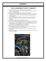
POLY-CARBONATE SAFETY WINDOW
NOTE: This should be done before mounting the main frame.
1. Disconnect gas shock at door. Remove the right side cab door from tractor
cab by removing hinge pins.
2. Remove the existing hardware and discard factory glass door.
3. Place small bead of adhesive seal in the bottom of the trim lock bubble bead.
4. Install trim lock bubble seal on polycarbonate starting at the center bottom
horizontal portion.
5. Install existing hardware removed from glass door on the polycarbonate.
6. Install the polycarbonate assembly in the cab with existing and supplied
hardware.
7. Press polycarbonate into place at upper front corner.
8. Then drill 3/16" pilot hole through polycarbonate and corner gusset of door jam.
9. Locate hole 1-1/4" from the edge of the lower rounded feature of the corner
gusset and center it from each end. Then drill out hole in polycarbonate with
15/32" diameter bit that is ONLY used for polycarbonate.
10. Drill out hole in gusset with 3/8" diameter bit for steel.
11. Install the poly door into place where factory door was removed (upper right
rear first). Refer the parts section for the details.
12. Install grommet into hole in polycarbonate.Then install supllied 1/4” nut into
corner gusset.
13. Secure upper right corner with supplied washer and capscrew. Refer to Parts
section for the details.
T6000 Saber Assembly Section 2-12
ASSEMBLY
MAIN FRAME MOUNTING
With an overhead hoist and / or jack-stands, raise one side of the frame up to the
correctly matching mounting holes. Install cap-screws and all other hardware as
shown in main frame parts section to secure the first side to the tractor casting.
Next raise the second side of the frame into position and secure to tractor as done
on first side. Now the ten capscrews, lockwashers and hex nuts can be installed to
join the two halves of the main frame together. Remove the cap-screws that secure
the main frame to the tractor one at a time and apply a thread locking agent.
Reinsert the cap-screws and tighten / torque to values noted in the torque chart
located in the maintenance section of this manual.
FRONT PUMP MOUNTING
Install the pump mounting bracket on the front of the tractor with cap-screws and
lock-washers as shown in the parts section illustration. DO NOT tighten fasteners
at this time.
Slide the pump drive shaft into the crankshaft adapter. The end with the shorter
splines should be inserted into the adapter (if applicable).
Slide the splined drive shaft coupler onto the pump drive shaft. Install the pump
onto the mounting bracket. NOTE: the shaft is offset to one direction, the pump
should be installed with the offset side on top. Install hardware for securing pump to
the pump mount, DO NOT tighten.
Align pump so that splined coupling can be moved back and forth by hand.
Tighten pump mounting bolts in succession rechecking for spline coupling
movement. Remove the pump mounting bracket bolts one at a time and apply a
tread locking agent. Tighten these bolts in succession, again checking for free
movement in the drive shaft. After all bolts are torqued, the end play on the drive
shaft should be 1/16” to 1/8”, and coupler should move freely with hand pressure. If
end play is less than 1/16”, grind the end of the shaft to achieve the proper end play.
If there is more than 1/4" of end play, return the shaft with specifications for a longer
shaft.
CAUTION: DO NOT START THE TRACTOR UNTIL ALL HOSES ARE
ATTACHED, TANK IS FILLED WITH PROPER OIL AND BALL VALVES ARE
OPEN! STARTING AT THIS TIME WILL CAUSE SERIOUS DAMAGE TO THE
PUMP.
HYDRAULIC TANK INSTALLATION
Install all fittings and tubes into tank and tank filter as shown in parts section
illustration. Insert tank sight glass into front side of the tank. Install the temperature
sensor (optional) or pipe plug into the side of the tank.
Place the tank in the mounting bracket on the main fame as shown in the parts
section.
Secure the tank in the mounting bracket with the tank strap and nylock nuts.
Install the filter gauge into the filter housing so that it points to the rear of the
tractor and is clearly visible to the operator.
The breather cap will be installed after tank is filled.
T6000 Saber Assembly Section 2-13
ASSEMBLY
GENERAL HOSE INSTALLATION
Refer to the parts section for detailed information about hoses and fittings for this
application.
When mounting the suction hose between the pump and the tank, the stainless
steel bands that are provided must be used. CAUTION: DO NOT use regular hose
clamps for this purpose. For protection of hoses in contact with metal edges, wrap
hoses with spit hose sections and fasten with hose clamps or zip ties as needed.
HOSE COVERING
Secure hoses together with zip ties wherever loose. Wrap the hoses between
the main boom and secondary boom with the yellow hose cover, secure with black
string provided. Where hoses may contact the frame or other edges, wrap with split
hose and secure with hose clamps or zip ties. On non cab units the pressure and
return hoses from the control valve will also need to be routed inside the protective
clear hose wrap. Cover the valve, valve fittings with the yellow hose cover and
secure with black string provided.
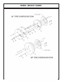
WHEEL WEIGHT MOUNTING
For all machines using a Saber Boom mower, a double wheel weight will be
required for the left side wheel. It will be necessary to mount the large wheel weight
in the wheel using the long cap-screws, lock-washers, flat-washers, and hex nuts per
diagram in the parts section. The smaller wheel weight will need to be used in
addition to the large one. This will be installed as shown in the parts section also.
Installation is most easily done with a small fork lift, inserting a fork in the center
slot of the wheel weight. The head of the cap-screws is to be toward the OUTSIDE
of the weight, with flat-washers on both inside and outside of the assembly. The left
rear tire must also be filled with a mixture of water and calcium chloride at about five
pound per gallon. Tire air pressure should be maintained at approximately 22 P.S.I.
TEMPERATURE GAUGE MOUNTING
(OPTIONAL)
Mount the temperature gauge where it is clearly visible to the operator. Attach the
green ( - ) wire from the negative post on the gauge to a grounded bolt on the tractor
frame. Remove paint if needed to make a good ground. Remove the pipe plug from
the side of the hydraulic reservoir, and install the temperature sensor using thread
sealing tape. Run the white wire from the ( S ) sensor post of the gauge to the
temperature sensor on the hydraulic reservoir tank.
Install lynch pin provided through hole on boom rest pin.
HAND RAIL MODIFICATION
The right side hand rail will need to be removed to allow room for the rear stowing
boom to run along side the cab. To remove the handrail, cut it off at the top and bottom
leaving approximately 2” on the tractor at each end. File the portions that are left to
remove any sharp edges. Plug / cover the portions that are left of the handrail with a
plastic cap.
T6000 Saber Assembly Section 2-14
ASSEMBLY
BOOM REST MOUNTING
With the main frame mounted on the tractor, refer to the parts section for the
hardware needed to install the boom rest. CAUTION: because of the shape and
size of the boom rest it will be somewhat unstable to lift into position. Special care
should be taken when installing the boom rest. Before lifting into position, install the
axle brace onto the boom rest as shown. Now raise the assembly into a horizontal
position and support it from the bottom with a floor jack towards the main frame
mounting plate. Line up the holes where the axle brace will mount to the main frame,
and install securing hardware loosely. Now raise the rear and align holes to mount to
axle. Install hardware with tread locking agent and tighten / torque as specified.
INSTALLING O-RING FITTINGS
Installing straight, 45 degree and 90 degree O-rings fittings requires that the O-ring,
washer and nut (A) be up against the swivel body (B). Insert the swivel and turn in until
the swivel is pointed in the right direction and the O-ring contact is made. Hold swivel
in set direction with a wrench and turn the O-ring nut away from the swivel body and
carefully tighten.
MAIN BOOM INSTALLATION
Install the boom swivel into the main frame as shown in the parts section using a
hoist. Line up holes in swivel and main frame for large swivel pin and insert pin.
Secure with hardware as shown. Inspect the inner boom end, grease hole in bearing
must align with boom grease zerks. Attach the inner end of the main boom to the
swivel bracket with the cylinder anchors mounting upward, and at a right angle to the
tractor. Secure it with the horizontal hinge pin. Secure the hinge pin in the boss with
capscrews, etc. (see parts section).
Install the fittings and hose to the butt end of the large main boom cylinder. Install
the travelock with the restrictor on the rod end of the main boom cylinder. These
should be facing the butt end of the cylinder after installation.
NOTE: Be sure to use teflon tape on all pipe fittings (except O-rings).
Install main boom cylinder on the main boom with the fittings facing upwards.
Attach the butt end to the cylinder to the swivel bracket anchor with the special
“bracket head” cylinder pin and roll pin shown in parts section. Attach the cylinder
rod end clevis to the main boom with the cylinder pin and two roll pins.
GREASE HINGE PIN ZERKS ON BOOM AFTER ASSEMBLY, ONCE UNDER
LOAD WITH BOOM ELEVATED AND AGAIN AT REST WITH BOOM
SUPPORTED
T6000 Saber Assembly Section 2-15
ASSEMBLY
SABER HOSE ROUTING
WARNING NOTE: The sudden release of hydraulic pressure could cause the
sudden movement of very heavy parts. Anyone in the way of these parts could be
severely hurt or killed. DO NOT ALLOW these hydraulic hoses to BREAK or BURST
in order to prevent hydraulic failure Make sure the hoses do not pinch or stretch as
boom moves. Measure TWICE, check TWICE then proceed with caution.
Connect the hoses to the preformed tubes and move the boom arm to the farthest forward position. Arrange the hoses in the clamp as shown in the illustration
above, with the 1” motor hoses to the outside, and loosely connect to the swivel.
Next, make sure there is enough slack for all hoses to pivot at the joint where the
main boom arm bends in the swivel and tighten the hoses in the clamp.
T6000 Saber Assembly Section 2-16
ASSEMBLY
Arrange the hoses in the clamp that attaches to the main frame as shown above,
with the 1” motor hoses closest to the main frame. Pull the hoses snug from the
swivel to the main frame clamps, when main boom is fully forward, and tighten the
hoses in the clamp.
Make sure the 1” motor hoses do not kink as the boom arm is moved into the
stowing position. If this happens the motor hoses will have to be tightened, because
there is too much hose between clamps.
T6000 Saber Assembly Section 2-17
ASSEMBLY
T6000 Saber Assembly Section 2-18
ASSEMBLY
DECK ATTACHMENT
Attach the head to the secondary boom using the pins and hardware shown in the
parts section to attach linkages. Install the square tube on the top of the head into
the head mount and secure using the mounting plate and hardware as shown. The
mount should be positioned to the left side of the cutter head. Install the deck pivot
cylinder using the pins and hardware also shown in the parts section.
Connect the fittings and hoses from the pivot cylinder to the small preformed
tubes on the boom arm. Connect the fittings and hoses from the motor to the large
preformed tubes on the boom arm.
Connect all remaining hoses from the control valve to the cylinders and / or
preformed tubes on the boom arm. Refer to parts section for diagrams.
Before proceeding to the final preparation step double check the
complete assembly from the main frame to the cutter head against the
diagrams in the parts section for proper placement and assembly of all
components.
CUTTERSHAFT BEARING ASSEMBLY
Tiger Part number 06520089
1. Belt drive end:
− Mount non-expansion bearing on this end first per bearing instructions.
2. Opposite belt drive
− Move snap ring to outer ring groove to create an expansion bearing. This allows
bearing to move axially within housing.
− Install bearing with snap ring set to outer ring groove.
− Slide bearing axially toward aforementioned snap ring.
Tighten per bearing instructions. This allows bearing to move away from center
of cutter shaft without creating a pre-load on the bearing.
EXTENDING ZERK ON FLAIL HEAD
Due to the belt shield covering the cutter shaft bearing on the flail head a hose,
elbow, & grease zerk have been added to the bearing. Remove the existing grease
zerk from the bearing and discard. Attach the elbow to the bearing. Next, the hose is
attached to the elbow and routed through the belt shield(shown below) and attached
to the outside of the shield. The additional zerk is connected to the end of the hose for
easier bearing maintenance.
T6000 Saber Assembly Section 2-19
ASSEMBLY
BOOM JOYSTICK CONTROL CALIBRATION
SUB-D
This Danfoss PVG32 control valve is now equipped with higher-resolution actuators
on Main Boom, Secondary Boom, Deck Roll, and Swivel functions. These actuators
have “active fault monitoring”. The Deck Shield section does not have “active fault
monitoring”. The joystick is unchanged and provides a ratio-metric voltage signal.
The neutral signal voltage is half or 50% of tractor supply voltage. A 25% signal
voltage will shift the valve spool to full “A-Port”, and 75% signal voltage will shift the
spool to full “B-Port” in the Main, Secondary, and Swivel valve sections. On the
Deck Roll function a 34% signal voltage will shift the valve spool to full “A-Port” and a
68% signal voltage will shift the spool to full “B-port”. If an actuator with active fault
monitoring receives a signal from the joystick that is less than 15% or greater than
85% of supply voltage the actuator will “fault out” and shut down. Also if there is an
internal failure in the actuator or if the spool position is greater than that specified by
the signal voltage from the joystick, the actuator will “fault out” and shut down. An
“active fault” condition causes the actuator to drive the spool to neutral, shut down,
and activate a “red” LED on the top of the actuator. The active fault can be canceled
by simply cycling the Master Switch “OFF” and then “ON”, which resets the fault
monitoring, and causes the LED on top of the actuator be “green” again.
The joystick control is equipped with signal adaption potentiometers.
These provide the capability to individually adjust the oil flow to each boom function.
It is important that the boom functions do not travel too fast. Excessive boom speed
can reduce the stability of the unit and decrease operator control.
Note: Use a Phillips screw driver and be sure to adjust the screws carefully! DO
NOT turn the potentiometers beyond their stopping point, potentiometers are very
delicate! Turning the “A” or “B” port potentiometers clockwise increases the oil flow
to increase the boom function speed, and turning them counterclockwise decreases
the oil flow to decrease the boom function speed. See the graphic on the next few
pages for help in adjusting.
T6000 Saber Assembly Section 2-20
ASSEMBLY
Run tractor at normal operating RPM to adjust the settings as follows.
Set the dead band compensation potentiometer first.
Set the dead band compensation potentiometer at 50%, or halfway between full
clockwise and full counter-clockwise.
Setting Signal Adaptation Potentiometers:
Disconnect the Deutsch connectors from the actuators of the valve. Use a Volt/Ohm meter to
measure signal voltage and adjust the signal adaptation potentiometers as needed. Pin #4 is
tractor supply voltage. Pin #1 is signal voltage from the joystick, and pin #3 is ground. First
measure supply voltage between pins 4 and 3. Then measure signal voltage between pins 1
and 3 while indexing the joystick function fully in both the “A” and “B” port direction. Divide the
signal voltage by the supply voltage to get signal voltage as a % of supply voltage. This
percentage should not be less than 25% or greater than 75% for the Main Boom, Secondary
Boom, or Swivel function. This percentage should not be less than 30% or greater than 62% for
the Deck Roll function. Note these initial settings for the Deck Roll function should prevent the
spool from shifting into float. After making this first adjustment to deck roll if the spool still goes
into float, adjust the “B” port screw additionally counterclockwise.
Reconnect Deutsch connectors on control cables to actuators on Danfoss valve. Run
tractor until hydraulic system is at operating temperature. Now refine the adjustments
of the signal adaptation potentiometers for both “A” and “B” ports for all proportional
functions to achieve the following function times. Note: turning potentiometer
clockwise increases the flow or the function speed, and turning them counterclockwise decreases the flow or the function speed. Note, if during this procedure the
trim potentiometer is set to full “counterclockwise” but the function is still too fast, use
the mechanical stops at the manual actuator end of the valve section to further limit
flow. Turn limit screw in or clockwise to limit flow. The upper limit screw limits flow to
“B-port”, and the lower limit screw limits flow to “A-port”. However DO NOT adjust the
limit screw on “B-port” of deck roll function. Limiting “B-port” will prevent “float”
function.
T6000 Saber Assembly Section 2-21
ASSEMBLY
MAIN BOOM: “A” Port, Boom UP: 7-9 Seconds
(Note: Extend secondary boom completely; roll deck to be level with ground, and lower
main boom until deck is on ground. Now index main boom “up” function and determine the
time required for main boom to rise completely.)
“B” Port, Boom Down:
6-8 Seconds
(Note: Extend secondary boom completely, roll deck to be level with ground, and raise the
main boom to “full up”. Then index the main boom “down” function to determine the amount
of time required for the deck to contact the ground. CAUTION: Stop the boom just as the
deck contacts the ground.)
SECONDARY
BOOM:
“A” Port, Boom Out: 8-10 Seconds
(Position main boom full up, roll deck out until deck cylinder is fully retracted, and bring
secondary boom in completely. Then index the secondary boom “out” function and determine
the time required for boom to extend out completely.)
“B” Port, Boom In:
8-10 Seconds
(Position the main boom full up, roll deck out until deck cylinder is fully retracted, and
extend secondary boom completely. Then index the secondary boom “in” function and
determine the time required for boom to come in.)
DECK ROLL: “A” Port, Deck Out: 7-9 Seconds
(Raise main boom to vertical, extend secondary boom out slightly so that deck can be
articulated without contacting the main boom, and roll deck in until deck cylinder is completely
extended. Then index the deck roll “out” function and determine the time required for the
deck to roll out.)
“B” Port, Deck In:
Target 7-9 Seconds (but DO NOT use Limit
Screw)
(Raise main boom to vertical, extend secondary boom out slightly so that deck can be
articulated without contacting the main boom, and roll deck out until deck cylinder is
completely retracted. Then index the deck roll “in” function and determine the time required
for the deck to roll in.)
BOOM
SWIVEL:
“A” Port, Boom Aft:
11-13 Seconds
(Extend booms completely; rotate head to be level with ground, lower main boom until deck
is just above ground, and swivel boom full forward. Then index the boom swivel “aft”
function and determine the time required for the boom to swivel aft. Use caution when doing
this, stop boom before main boom contacts tire.)
“B” Port, Boom Forward:
11-13 Seconds
(Extend booms completely, rotate head to be level with ground, lower main boom until deck
is just above ground, and swivel boom aft and until near tire. Then index the boom swivel
“forward” function and determine the time required for the boom to swivel full forward.)
T6000 Saber Assembly Section 2-22
ASSEMBLY
T6000 Saber Assembly Section 2-23
ASSEMBLY
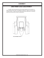
2WD FRONT AXLE ADJUSTMENT
In order to prevent interference with mounted equipment, the front axle on a
2WD T6000 tractor will have to be adjusted outwards by 2 holes on each side (see
illustration below). Double check the wheel spacing after adjustment by oscillating
and turning the tires fully to check for interference.
T6000 Saber Assembly Section 2-24
ASSEMBLY
FINAL PREPARATION FOR OPERATION
Place operators safety and operation decals on the steering column and side
counsel where they are clearly visible to the operator. These decals should be
understood by each operator of the machine in conjunction with the safety and
operation section of this book. The decals are to remain in good condition as a
reminder to the operator, and should be replaced if damaged.
Finally, all bosses, pins and pivot points will need to be greased as instructed in
the maintenance section of this manual. The hydraulic reservoir can also be filled
with the recommended fluid (see maintenance section) and the filter installed in the
top of the tank. Double check all fittings and fasteners BEFORE starting tractor.
Also secure any loose hoses together with zip ties and wrap with split hoses where
friction may occur on the hoses.
BEFORE starting or operating the tractor you must read and understand
the safety and operation sections of this manual completely.
BE SURE THE BALL VALVES ARE OPEN! Start tractor and allow instruments
to stabilize. Using a piece of paper or cardboard as noted in the safety and
maintenance sections, check all fittings and connections for hydraulic leaks.
If a leak is found, you must shut down the tractor, set the cutter on the ground.
Before attempting to fix the leak, you must actuate the lift valve handles several times
to relieve any pressure in the lines.
Before operating the mower, the cutter head and boom should be slowly
moved throughout the full range of motion. Watch for any condition that would cause
pinching or excess stress on the hoses. The steering and front axle travel should
also be carefully moved through their full range of motion. If any condition occurs in
which the hoses contact the tires, the steering and / or front axle travel may need to
be limited as described in the tractor operators manual. This should also be done if
the tires rub, or are extremely close to any other part of the mower such as the
hydraulic tank or draft beam. This may include adding shims, or adjusting stop bolts
in the tractor front to solve the problem. While checking motion, you should also
check that the control circuits are connected according to the operators decal for the
valve handles.
MOWER TESTING
Take the tractor to a place free of loose objects on the ground. Operate the
cylinders through their full range of motion again, to clear the lines of air. Follow the
instructions in the operation section to operate the mower. Vibration of the mower
should be minimal at all times. After a 5 minute test run, the knife bolts should be
retorqued and once again after the first few hours of operation.
If any parts of this assembly section, or any other section of this
manual are not clearly understood you must contact your dealer or the
address on the front of this manual for assistance!
T6000 Saber Assembly Section 2-25
ASSEMBLY
T6000 Saber Assembly Section 2-26
OPERATION SECTION
Operation Section 3-1
©2011 Alamo Group Inc.
OPERATION
OPERATION
TIGER SABER BOOM MOWER
OPERATING INSTRUCTIONS
Safety is of primary importance to the owner/operator and to the manufacurer. Tiger Saber Booms are
manufactured with quality material by skilled workers. The first section of this manual includes a list of Safety
Messages, that, if followed, will help protect the operator and bystanders from injury or death. The Saber Boom
is equipped with safety warning decals, protective deflectors, shields and other safety features to provide
operator and passerby protection, however, no shielding is 100% accurate. All safety equipment and safety
warning decals must be maintained on the unit in good operational condition at all times. It is the operators
responsibility to be knowledgeable of all potential hazards and to take every reasonable precaution to ensure
oneself, others, animals, and property are not injured or damaged by the boom unit, tractor or a thrown object.
Do not operate the boom and attached head if bystanders,passerby, pets or livestock are within 300 feet of the
unit. Many of the messages will be repeated throughout the manual. The owner / operator / dealer should
know these Safety Messages and Operating Instructions before assembly and be aware of the hazards of
operating this mower during assembly, use, and maintenance of this equipment.
The Safety Alert Symbol combined with a signal word, as seen below, is intended to warn the owner / operator
ofimpending hazards and the degree of injury possible during operation.
Indicates an imminently hazardous situation that, if not avoided, WILL result in DEATH OR
VERY SERIOUS INJURY.
Indicates an imminently hazardous situation that, if not avoided, COULD result in DEATH
OR SERIOUS INJURY.
Indicates an imminently hazardous situation that, if not avoided, MAY result in MINOR
INJURY.
Identifies special instructions or procedures that, if not strictly observed, could result in
damage to, or destruction of the machine, attachments or the environment.
NOTE: Identifies points of particular interest for more efficient and convenient operation or
repair.
This section of the Operator’s Manual is designed to familiarize, instruct and educate operators to the safe and
proper use of the Saber Boom. Pictures contained in this section are intended to be used as a visual aid to
assist in explaining the operation of a Saber Boom and are not specific to a Saber Boom. Some pictures may
show shields removed to enhance visual clarity. NEVER operate the boom unit without all safety equipment in
place and in good operational condition. The operator must be familiar with the boom unit and tractor
operation and all safety practices before beginning operation. Proper operation, as detailed in this manual, will
help ensure years of safe and satisfactory use of the Saber Boom.
READ AND UNDERSTAND THE ENTIRE OPERATING INSTRUCTIONS AND SAFETY SECTION OF THIS
MANUAL AND THE TRACTOR MANUAL BEFORE ATTEMPTING TO USE THE TRACTOR AND
IMPLEMENT. If you do not understand any of the instructions, contact your nearest authorized dealer for a
full explanation. Pay close attention to all safety signs and safety messages contained in this manual and
those affixed to the implement and tractor. OPS-U- 0001
READ, UNDERSTAND, and FOLLOW the following Safety Messages. Serious injury or
death may occur unless care is taken to follow the warnings and instructions stated in the
Safety Messages. Always use good common sense to avoid hazards. (SG-2)
Si no lee ingles, pida ayuda a alguien que si lo lea para que le traduzca las
medidas de seguridad. (SG-3)
Saber
©2011 Alamo Group Inc.
Operation Section 3-2
OPERATION
1.OPERATOR REQUIREMENTS
•
•
•
•
•
•
•
Always Wear Safety Glasses
Hard Hat
Steel Toe Safety Footwear
Gloves
Hearing Protection
Close Fitting Clothing
Respirator or Filter Mask (depends on
operating conditions) OPS-U- 0002
NEVER use drugs or alcohol immediately before or while operating the
Tractor and Implement. Drugs and alcohol will affect an operator’s
alertness and coordination and therefore affect the operator’s ability to
operate the equipment safely. Before operating the Tractor or Implement,
an operator on prescription or over-the-counter medication must consult
a medical professional regarding any side effects of the medication that
would hinder their ability to operate the Equipment safely. NEVER
knowingly allow anyone to operate this equipment when their alertness or
coordination is impaired. Serious injury or death to the operator or others
could result if the operator is under the influence of drugs or alcohol. (SG-27)
Saber
©2011 Alamo Group Inc.
Operation Section 3-3
OPERATION
Safe operation of the unit is the responsibility of a qualified operator. A qualified operator has read and
understands the implement and tractor Operator’s Manuals and is experienced in implement and tractor
operation and all associated safety practices. In addition to the safety messages contained in this manual,
safety signs are affixed to the implement and tractor. If any part of the operation and safe use of this
equipment is not completely understood, consult an authorized dealer for a complete explanation.
If the operator cannot read the manuals for themselves or does not completely understand the operation of the
equipment, it is the responsibility of the supervisor to read and explain the manuals, safety practices, and
operating instructions to the operator.
Safe operation of equipment requires that the operator wear approved Personal Protective Equipment (PPE)
for the job conditions when attaching, operating, servicing, and repairing the equipment. PPE is designed to
provide operator protection and includes the following safety wear:
PERSONAL PROTECTIVE EQUIPMENT (PPE)
OPERATION
2.TRACTOR REQUIREMENTS
In addition to tractor horsepower and size required to operate the boom unit, the tractor must also be properly
equipped to provide operator protection, to alert approaching vehicle drivers of the tractor’s presence, and to
ensure tractor stability when mowing with the boom fully extended.
Tractor Requirements and Capabilities
OPERATION
•
•
•
•
ASAE approved Roll-Over Protective Structure (ROPS) or ROPS cab and seat belt.
Operator Protection .......................... Tractor must be equipped with protective structure such as operator’s
cage or lexan window to protect operator from thrown object and falling objects
Tractor Safety Devices .................... Slow Moving Vehicle (SMV) emblem, lighting,
Tractor Ballast ................................. As required to maintain at least 1500 lbs. on left rear tire
2.1 ROPS and Seat Belt
The tractor must be equipped with a Roll-Over-Protective-Structure (ROPS) (tractor cab or roll-bar) and seat
belt to protect the operator from falling off the tractor, especially during a roll over where the driver could be
crushed and killed. Only operate the tractor with the ROPS in the raised position and seat belt fastened.
Tractor models not equipped with a ROPS and seat belt should have these life saving features installed by an
authorized dealer. OPS-U- 0003
Operate this Equipment only with a Tractor equipped with an approved rollover-protective system (ROPS). Always wear seat belts. Serious injury or
even death could result from falling off the tractor--particularly during a turnover
when the operator could be pinned under the ROPS. (SG-7)
2.2 Operator Thrown Object Protection
The tractor must be equipped with protective
equipment to shield the operator from falling and
thrown objects. For cab tractors, the tractor must
be equipped with an operator safety screen on its
right side or the right side windows must be fitted
with a shatter resistant safety window. For noncab tractors, the tractor must be equipped with a
ROPS and operator protective safety cage that
provides protection to the right and above the
operator seat. DO NOT remove the ROPS from
non-cab tractors to equip a safety cage.
OPS-B- 0001
Never operate the Tractor and Mower Unit without an OPS (Operators
Protective Structure) or Cab to prevent injury from objects thrown from
ground or from overhead trimming. Stop mowing if workers or passersby
are within 300 feet. (SBM-9)
Saber
©2011 Alamo Group Inc.
Operation Section 3-4
OPERATION
2.3 Tractor Lighting and SMV Emblem
If the tractor will be operated near or traveled on a
public roadway it must be equipped with proper
warning lighting and a Slow Moving Vehicle (SMV)
emblem which are clearly visible from the rear of
the unit. Most tractor’s have different settings for
operating and transporting lighting. Refer to the
tractor operator’s manual for using the tractor’s
light switch and operating the turn signals.
OPS-B- 0017
To ensure tractor stability when operating on flat surfaces the left rear tractor tire MUST exert a minimum
down force (weight) of 1500 lbs. on the ground when the tractor is on level ground, its boom is fully extended
and the mower head is horizontal and two feet above the ground. For units which have the ability to operate
on either side of the tractor, these requirements must also be met for the right side tire when the boom is
extended to the left side as described above. A tractor that does not meet this criteria is DANGEROUS and
should not be operated as upset of the unit can occur resulting in possible serious injury and property
damage. NOTE: All factory mounted units are tested and meet the ballast requirement before shipment;
further testing is not required unless the unit is operated in a manner other than what is considered standard
operating conditions.
If the unit is operated on slopes greater than 5°,
additional counterweight will be required.
Operation of the unit on slopes greater than 11
percent (6.4 degrees) is not recommended under
any circumstances. On a tractor with a 96” outside
to outside tire spread, an 11 percent (6.4 degrees)
slope occurs when one rear tractor tire is about 8”
lower than the other rear tire. OPS-B- 0018
Saber
©2011 Alamo Group Inc.
Operation Section 3-5
OPERATION
2.4 Tractor Ballast
OPERATION
3.GETTING ON AND OFF THE TRACTOR
Before getting onto the tractor, the operator must read and completely understand the implement and tractor
operator manuals. If any part of either manual is not completely understood, consult an authorized dealer for
a complete explanation. OPS-U- 0007
OPERATION
Do not mount or dismount the Tractor while the tractor is moving. Mount
the Tractor only when the Tractor and all moving parts are completely
stopped. (SG-12)
Never operate the Tractor and Mower Unit without an OPS (Operators
Protective Structure) or Cab to prevent injury from objects thrown from
ground or from overhead trimming. Stop mowing if workers or passersby
are within 300 feet. (SBM-9)
3.1 Boarding the Tractor
Use both hands and equipped handrails and steps for support when boarding the tractor. Never use control
levers for support when mounting the tractor. Seat yourself in the operator’s seat and secure the seat belt
around you.
Never allow passengers to ride on the tractor or attached equipment. Riders can easily fall off and be
seriously injured or killed from falling off and being ran over. It is the operator’s responsibility to forbid all extra
riders at all times. OPS-U- 0008
Never allow children to operate, ride on, or come close to the Tractor or
Implement. Usually, 16-17 year-old children who are mature and
responsible can operate the implement with adult supervision, if they
have read and understand the Operator’s Manuals, been trained in
proper operation of the tractor and Implement, and are physically large
enough to reach and operate the controls easily. (SG-11)
3.2 Dismounting the Tractor
Before dismounting the tractor, idle the tractor engine down, disengage the head and retract the boom arm to
the transport position. Park the tractor on a level surface, place the transmission in neutral and set the
parking brake. Shut down the tractor engine, remove the key, and wait for all motion to come to a complete
stop before exiting the operator’s seat. NEVER leave the seat until the tractor, its engine, and mower head
movement have come to a complete stop.
Use hand rails and extra steps when exiting the tractor. Be careful of your step and use extra caution when
mud, ice, snow, and other matter has accumulated on the steps and handrails. Never rush or jump off the
tractor. OPS-B- 0002
Saber
©2011 Alamo Group Inc.
Operation Section 3-6
OPERATION
BEFORE leaving the tractor seat, always set the parking brake and/or set
the tractor transmission in parking gear, disengage the PTO, stop the
engine, remove the key, and wait for all moving parts to stop. Place the
tractor shift lever into a low range or parking gear to prevent the tractor
from rolling. Never dismount a Tractor that is moving or while the engine
is running. Operate the Tractor controls from the tractor seat only. (SG-9)
The operator must have a complete understanding of the placement, function, and operational use of all
tractor controls before starting the tractor. Review the tractor operator’s manual and consult an authorized
dealer for tractor operation instructions if needed.
Essential Tractor Controls:
• Locate the ignition key/switch
• Locate the engine shut off control
• Locate the hydraulic control levers
• Locate the light control lever
• Locate the brake pedals and clutch
• Locate the PTO control
• Locate the 3 point hitch control lever
• Locate the boom operating controls (joystick or valve bank)
Before starting the tractor ensure the following:
•
•
•
•
•
•
•
Conduct all pre-start operation inspection and service according to the tractor operator’s manual.
Make sure all guards, shields, and other safety devices are securely in place.
The parking brake is on.
The tractor transmission levers are in park or neutral.
The boom operating controls are in the neutral and off position.
The PTO control lever is disengaged.
The hydraulic remote control levers are in the neutral position.
Refer to the tractor owner’s manual for tractor starting procedures. Only start the tractor while seated and
belted in the tractor operator’s seat. Never bypass the ignition switch by short circuiting the starter solenoid.
After the tractor engine is running, avoid accidental contact with the tractor transmission to prevent sudden
and unexpected tractor movement. OPS-B- 0003
Never run the Tractor engine in a closed building or without adequate ventilation. The
exhaust fumes can be hazardous to your health. (SG-23)
Saber
©2011 Alamo Group Inc.
Operation Section 3-7
OPERATION
4.STARTING THE TRACTOR
OPERATION
OPERATION
Start tractor only when properly seated in the Tractor seat. Starting a
tractor in gear can result in injury or death. Read the Tractor operators
manual for proper starting instructions. (SG-13)
When rotating parts are in motion, serious injury may occur if caution is not used or
danger is not recognized. Never allow bystanders with 300 yards of the machine when
mower is in operation.
Be sure the ball valve on the mower hydraulic tank are OPEN before starting the tractor.
Serious damage to the hydraulic system can occur if the valves are not open
5.PRE-OPERATION INSPECTION AND SERVICE
Before each use, a pre-operation inspection and service of the implement and tractor must be performed.
This includes routine maintenance and scheduled lubrication, inspecting that all safety devices are equipped
and functional, and performing needed repairs. DO NOT operate the unit if the pre-operation inspection
reveals any condition affecting safe operation. Perform repairs and replacement of damaged and missing
parts as soon as noticed. By performing a thorough pre-operation inspection and service, valuable down time
and repair cost can be avoided. OPS-U-0029
Periodically inspect all moving parts for wear and replace when
necessary with authorized service parts. Look for loose fasteners, worn
or broken parts, and leaky or loose fittings. Make sure all pins have
attaching hardware. Serious injury may occur from not maintaining this
machine in good working order. (SG-21_A)
All Safety Shields, Guards and Safety devices including (but not
limited to) - the Deflectors, Chain Guards, Steel Guards, Gearbox
Shields, PTO integral shields, and Retractable Door Shields should
be used and maintained in good working condition. All safety
devices should be inspected carefully at least daily for missing or broken components.
Missing, broken, or worn items must be replaced at once to reduce the possibility of
injury or death from thrown objects, entanglement, or blade contact. (SGM-3)
Saber
©2011 Alamo Group Inc.
Operation Section 3-8
OPERATION
5.1 Tractor Pre-Operation Inspection/Service
5.2 Boom Unit Pre-Operation Inspection and Service
Inspect and service the boom arm and head prior to operation. Damaged and/or broken parts should be
repaired and/or replaced immediately. To ensure the unit is ready for operation, conduct the following:
OPS-B- 0020
Periodically inspect all moving parts for wear and replace when
necessary with authorized service parts. Look for loose fasteners, worn
or broken parts, and leaky or loose fittings. Make sure all pins have
attaching hardware. Serious injury may occur from not maintaining this
machine in good working order. (SG-21_A)
Saber
©2011 Alamo Group Inc.
Operation Section 3-9
OPERATION
Refer to the tractor operator’s manual to ensure a
complete pre-operation inspection and scheduled
service
is
performed
according
to
the
manufacturers recommendations. The following
are some of the items that require daily service and
inspection:
• Tire condition/air pressure
• Wheel lug bolts
• Steering linkage
• PTO shield
• SMV sign is clean and visible
• Tractor’s lights are clean and functional
• Tractor Seat belt is in good condition
• Tractor ROPS is in good condition
• ROPS is in the raised position
• No tractor oil leaks
• Radiator free of debris
• Engine oil level and condition
• Engine coolant level and condition
• Power brake fluid level
• Power steering fluid level
• Fuel condition and level
• Sufficient lubrication at all lube points
• Air filter condition OPS-U-0030
OPERATION
OPERATION
The operator’s manual and safety signs affixed on
the unit contain important instructions on the safe
and proper use of the equipment. Maintain these
important safety features on the implement in good
condition to ensure the information is available to
the operator at all times.
• Ensure all safety signs are in place and legible.
Replace missing, damaged, and illegible
decals. OPS-U- 0011_A
FRAME ASSEMBLY
• Inspect condition of mounting frame weldment.
• Inspect condition of Swivel Assy.
• Ensure all bolts and screws are in position and are
properly torqued.
• Ensure all pins are in place and fastened with
screws.
• Ensure frame is properly mounted to tractor and
hardware is propely installed and tightened.
OPS-B- 0021_SBR
Turret Frame Assy.
Never Leave the mower unattended while the head is in the raised
position. The mower could fall causing serious injury to anyone who
might inadvertently be under the mower. (SBM-4)
Relieve hydraulic pressure prior to doing any maintenance or repair work on the Implement.
Place the Mower Head on the ground or securely supported on blocks or stands, disengage
the PTO, and turn off the engine. Push and pull the control Levers or Joystick several times
to relieve pressure prior to starting any maintenance or repair work. (SBM-6)
Saber
©2011 Alamo Group Inc.
Operation Section 3-10
OPERATION
Never attempt to lubricate, adjust, or remove material from the Implement while it is in
motion or while tractor engine is running. (SG-20)
HYDRAULIC LINE INSPECTION
• Check for hydraulic leaks along hoses,
cylinders and fittings. IMPORTANT: DO NOT
use your hands to check for oil leaks. Use a
piece of heavy paper or cardboard to check for
hydraulic oil leaks.
• Inspect the condition of the valve mounting.
• Ensure fittings are properly connected.
OPS-B- 0023_D
Do not operate this Equipment with hydraulic oil or fuel leaking. Oil
and fuel are explosive and their presence could present a hazard. Do
not check for leaks with your hand! High-pressure oil streams from
breaks in the line could penetrate the skin and cause tissue damage
including gangrene. To check for a hose leak, SHUT the unit ENGINE
OFF and remove all hydraulic pressure. Wear oil impenetrable gloves,
safety glasses and use Cardboard to check for evidence of oil leaks. If
you suspect a leak, REMOVE the HOSE and have it tested at a Dealer.
If oil does penetrate the skin, have the injury treated immediately by a
physician knowledgeable and skilled in this procedure. (SG-15)
Saber
©2011 Alamo Group Inc.
Operation Section 3-11
OPERATION
BOOM ARM ASSEMBLY
• Inspect condition of each arm section weldment
• Ensure all pins are in place.
• Ensure all bolts, nuts and rollpins are properly
installed.
• Check condition of bushings at boom pivot
points and hydraulic cylinder tangs.
• Ensure each hydraulic cylinder is installed and
retained correctly. Ensure the proper size pins
are used to retain the cylinders in place and are
secured properly. OPS-B- 0022_D
OPERATION
OPERATION
HYDRAULIC PUMP/OIL RESERVOIR
• Check oil reservoir level and oil condition. (Add
specific type oil if low)
• Change hydraulic oil filter and hydraulic oil
according to maintenance schedule.
• Ensure there are no oil leaks and fitting are
properly connected
• Inspect overall condition of hydraulic pump.
• Inspect pump drive shaft.
Check the fluid level in the Hydraulic Tank on the
Tractor, and add oil if required. As the air has been
forced out of the Cylinders and Hoses, it goes into the Hydraulic Tank and reduces the volume of oil. Maintain
the oil level within the sight gauge located on the side of the reservoir. Never fill the tank above the sight gauge
to allow for the expansion of the oil. The tank maintains pressure after the mower has been run. Stand off to
one side when removing the breather cap element to prevent possible injury. OPS-B 0024_E
Attention: Oil Filler Cap is also the Pressure Relief Cap.
Remove cap slowly to relieve pressure before removing cap completely. Stay clear to
prevent being scalded with hot oil that may spray out of the tank that is still pressurized and
may cause serious injury to eyes, face, and exposed skin. (Ops-0001-MISC)
Avoid contact with hot surfaces including hydraulic oil tanks, pumps, motors, valves and
hose connections. Relieve hydraulic pressure before performing maintenance or repairs.
Use gloves and eye protection when servicing hot components. Contact with a hot surface
or fluid can cause serious injury from burns or scalding. (SG-34)
Saber
©2011 Alamo Group Inc.
Operation Section 3-12
OPERATION
Do not put hands or feet under mower decks. Blade Contact can result
in serious injury or even death. Stay away until all motion has stopped
and the decks are securely blocked up. (SGM-09)
All Safety Shields, Guards and other safety devices including (but not limited to) Deflectors, Steel Guards and Gearbox Shields must be used and maintained in good
working condition. All safety devices should be inspected carefully at least daily for missing
or broken components. Missing, broken, or worn items must be replaced at once to reduce
the possibility of injury or death from thrown objects, entanglement, or blade contact. (SSM-07)
Saber
©2011 Alamo Group Inc.
Operation Section 3-13
OPERATION
ROTARY HEAD INSPECTION
• Inspect blades and blade bolts for looseness
and excessive wear. Rotate to 90° to make
for checking easier. Replace damaged, worn,
and missing blades as complete sets to
maintain rotary balance.
• Ensure motor bolts and nuts are tightened to
the appropriate torque.
• Ensure rubber deflectors are in position and
not damaged. Replace worn, broken, and
missing sections immediately.
• Ensure hydraulic lines are properly connected
to the hydraulic motor. Check for hydraulic
leaks along hoses and fittings. DO NOT use
your hands to check for oil leaks. Use a piece
of heavy paper or cardboard to check for
hydraulic oil leaks.
• Inspect the condition of deck skid shoes and hardware. OPS-B- 0025
OPERATION
OPERATION
Boom PRE-OPERATION Inspection
Mower ID#________________
Make ____________________
Date:
Shift
________________
____________________
Before conducting the inspection, make sure the tractor engine is off, all rotation has
stopped and the tractor is in park with the parking brake engaged. Make sure the
mower is resting on the ground or securely blocked up and all hydraulic pressure has
been relieved.
Table 1:
Condition at Start
of Shift
Item
Specific Comments
if not O.K.
The Operator’s Manual is in the tractor
All safety decals are in place and legible
The mounting frame bolts are in place and tight
The boom connection bolts & pins are tight
There are no cracks in boom
The hydraulic cylinders pins are tight
The hydraulic pump hose connections are tight
The hydraulic valve controls function properly
There are no leaking or damaged hoses
The hydraulic oil level is full
There is no evidence of hydraulic leaks
The blades are not chipped, cracked or bent
The blade bolts are tight
The deflectors are in place and in good condition
The boom shields are in place and in good condition
The skid shoes are in good condition and tight
There are no cracks or holes in boom deck
The hydraulic motor mounting bolts are tight
The boom head spindle housing is tight and lubricated
Operator’s Signature:
DO NOT OPERATE an UNSAFE TRACTOR or MOWER
Saber
©2011 Alamo Group Inc.
Operation Section 3-14
OPERATION
Tractor PRE-OPERATION Inspection
Mower ID#________________
Make ____________________
Date:
Shift
________________
____________________
Condition at Start
of Shift
Item
Specific Comments
if not O.K.
The flashing lights function properly
The SMV Sign is clean and visible
The tires are in good condition with proper pressure
The wheel lug bolts are tight
The tractor brakes are in good condition
The steering linkage is in good condition
There are no visible oil leaks
The hydraulic controls function properly
The ROPS or ROBS Cab is in good condition
The seatbelt is in place and in good condition
The 3-point hitch is in good condition
The drawbar pins are securely in place
The PTO master shield is in place
The engine oil level is full
The brake fluid level is full
The power steering fluid level is full
The fuel level is adequate
The engine coolant fluid level is full
The radiator is free of debris
The air filter is in good condition
Operator’s Signature:
DO NOT OPERATE an UNSAFE TRACTOR or MOWER
This Inspection Form may be freely duplicated for extra copies.
Saber
©2011 Alamo Group Inc.
Operation Section 3-15
OPERATION
Before conducting the inspection, make sure the tractor engine is off, all rotation
has stopped and the tractor is in park with the parking brake engaged. Make sure
the mower is resting on the ground or securely blocked up and all hydraulic
pressure has been relieved.
OPERATION
5.3 Cutting Component Inspection
OPS-U-0031
OPERATION
Inspect blade pan and blade assembly for the following:
Inspect the Blades daily for abnormal wear. REPLACE BOTH BLADES on that carrier
IMMEDIATELY if either blade has:
•
•
•
•
•
Become bent or deformed from it’s original shape or
Any cracks are visible, or
Deep gouges in the blade’s surface are present, or
Gouges or chipped areas in the cutting edge are larger than 1/2”(12.7mm), or
The material on the leading edge has been worn away by more than 1/2(12.7mm)”
Failure to replace abnormally worn blades may lead to catastrophic failure of the blades and ejection of the
broken part with tremendous force which may cause serious bodily injury or death. OPS-U-0032
Saber
©2011 Alamo Group Inc.
Operation Section 3-16
OPERATION
5.4 Blade Bolt Inspection
Inspect Blade Bolt Head daily for wear as followed:
OPERATION
Inspect the Blade Bolt Heads daily for abnormal wear. REPLACE BOTH BLADE BOLTS on
the Blades IMMEDIATELY if either blade bolts has:
• Visible cracks or
• If the recessed area on blade bolt is worn off or
• If Blade Bolt has gouges or chipped areas.
Failure to replace abnormally worn blade bolts may lead to catastrophic failure of the blades and ejection of
the broken part which may cause serious bodily injury or death.
Always replace Blade Bolts with new bolts whenever replacing the Blades. OPS-U-0037
Saber
©2011 Alamo Group Inc.
Operation Section 3-17
OPERATION
OPERATION
6.JOYSTICK CONTROL
Saber
©2011 Alamo Group Inc.
Operation Section 3-18
OPERATION
JOYSTICK FW/BACK MOVES MAIN BOOM
LEFT JOYSTICK ROLLER MOVES DECK ROLL
Saber
©2011 Alamo Group Inc.
Operation Section 3-19
OPERATION
JOYSTICK LEFT/RIGHT MOVES SECONDARY
BOOM
OPERATION
OPERATION
RIGHT JOYSTICK
SWIVEL
ROLLER
MOVES
BOOM
SHIELD SWITCH(on switch box) OPERATES
SAFETY SHIELD
6.1 Switchbox
The Safety Shield lever opens and closes the shield
located on the front of the cutter head. When
moving at or near the ground, always have the
shield in the closed position. When moving in the
brush or in trees above ground level the shield may
be opened for easier cutting. Read and follow the
warnings on the decal shown on the next page.
Saber
©2011 Alamo Group Inc.
Operation Section 3-20
OPERATION
OPERATION
Never Leave the mower unattended while the head is in the raised
position. The mower could fall causing serious injury to anyone who
might inadvertently be under the mower. (SBM-4)
Check to make sure mower switch is in the “OFF” position. The unit is designed not to
start if the switch is in the “ON” position. If tractor starts with switch on, turn off tractor and
contact your local Tiger dealership for assistance.
Start the tractor and allow the instruments to stabilize. Without starting the mower,
practice positioning the boom and deck. Remember speed and skill will be attained easier if the necessary time
is spent familiarizing yourself with the machine and its operations. When you feel comfortable at controlling the
position of the mower, return the mower to the travel position, and transport the mower to the desired mowing
location.
If mowing for the first time with a Tiger Saber Boom Mower, we recommend choosing a ditch or area relatively
flat with a minimum of sign posts, guard rails, etc. As always, you should inspect the area for other objects that
can cause potential hazards.
Saber
©2011 Alamo Group Inc.
Operation Section 3-21
OPERATION
OPERATION
6.2 Main Control Switch Box
The Mower Control switch turns the mower “ON” and “OFF”. This switch is to be in the “OFF” position to start
the tractor. If the switch is “ON” and the tractor ignition switch is turned to “ON” the red “mower run” indicator
light will com on. However, the tractor will not start again with the Mower Control switch in the “ON” position.
Upon starting the tractor the “mower run” indicator light may flash briefly, and may flash briefly again when the
tractor is shut down.
If tractor starts with switch on, turn off tractor and contact your local Tiger dealership for
assistance.
NOTE: DO NOT operate mower head while boom is in the boom rest! Red “Mower Run”
light indicates mower is “ON” when tractor engine is running.
The boom functions are controlled by an electric joystick. The Joystick Master Switch enables the joystick
control for controlling the boom motion functions. This switch is to be in the “OFF” position when starting the
tractor and when boom is stowed for transporting the machine.
If the joystick is not operating properly, turn the master switch to the “OFF” position. Install
the manual valve handle onto valve and operate the functions individually to stow boom.
After boom is stowed in rest, transport the unit to the maintenance facility and contact your
Tiger dealer for assistance.
DO NOT attempt to operate the valve manually for mowing operations!
Note: Pushing manual valve handles “out” or “away” from the tractor cab will bring the main boom “up”,
secondary boom “out”, roll deck “out” and swivel boom “aft”. Pulling manual handles toward cab will let main
boom “down”, secondary boom “in”, roll deck “in”, swivel boom “forward”, and “close” the safety shield.
Saber
©2011 Alamo Group Inc.
Operation Section 3-22
OPERATION
The deck float is to be used only when mowing with a flail head, using the deck float with
a rotary head may damage the mower.
The Safety Shield switch opens and closes the shield located on the front of the cutter head. When mowing at
or near the ground, always have the shield in the closed position. When mowing in brush or in trees above
ground level the shield may be opened for easier cutting. Read and follow the warnings on the decal shown
below.
The Travel Lock function locks the mower head in the up-right position for road travel.
Prepare unit for travel by rolling deck completely out (mower deck rolled back adjacent to
secondary boom.) Then place main and secondary booms in boom rest. The Travel Lock
switch can now be engaged.
NOTE: The tractor ignition switch and the Master Switch must be “ON” and the Travel Lock must be “OFF” to
allow articulation of the mower deck.
Saber
©2011 Alamo Group Inc.
Operation Section 3-23
OPERATION
The Master Switch also provides power to the “Deck Float”, “Shield” and “Travel Lock” Functions of the mower
deck.
The Deck Float function allows the ground roller of the flail mower head to follow the contour of the ground. To
operate the deck float function, the Master switch must be in the “ON” position and the Travel Lock switch must
be in the “OFF” position. Lower the mower head to just touch the ground, then turn the deck float switch “ON”.
The Deck Float is to be used ONLY when the flail mower head is on the ground. The
mower head CAN NOT be controlled with the joystick when Deck Float is “ON”.
OPERATION
OPERATION
7.DRIVING THE TRACTOR AND IMPLEMENT
Safe tractor transport requires the operator to possess a thorough knowledge of the model being operated
and precautions to take while driving with an attached implement. Ensure the tractor has the capacity to
handle the weight of the boom and the tractor operating controls are set for safe transport. To ensure safety
while driving the tractor with a boom, review the following.
Read all safety instructions. Decals on the Boom warn you of particular and multiple hazards. Some decals
are attached close to part of the Boom where there is a possible hazard. Read and make sure you
understand the safety messages before you operate the implement. Keep all decals clean and readable.
Replace lost or damaged decals, refer to safety section for more information.
Keep all person's well clear of mower since blades can throw objects with great velocity for a considerable
distance! KEEP CLEAR! OPS-B- 0005
Never operate the Tractor or Implement until you have read and
completely understand this Manual, the Tractor Operator’s Manual, and
each of the Safety Messages found in the Manual or on the Tractor and
Implement. Learn how to stop the tractor engine suddenly in an
emergency. Never allow inexperienced or untrained personnel to operate
the Tractor or Implement without supervision. Make sure the operator
has fully read and understood the manuals prior to operation. (SG-4)
Always maintain the safety signs in good readable condition. If the safety signs are missing,
damaged, or unreadable, obtain and install replacement safety signs immediately. (SG-5)
Saber
©2011 Alamo Group Inc.
Operation Section 3-24
OPERATION
7.1 Starting the Tractor
The procedure to start the tractor is model specific.
Refer to the tractor operator’s manual for starting
procedures for your particular tractor. Consult an
authorized dealer if the starting procedure is
unclear. Ensure the 3-point control lever is in the
lowered position and the PTO is disengaged before
starting the tractor. OPS-U-0033
Saber
©2011 Alamo Group Inc.
Operation Section 3-25
OPERATION
Transport only at speeds where you can maintain control of the
equipment. Serious accidents and injuries can result from operating this
equipment at high speeds. Understand the Tractor and Implement and
how it handles before transporting on streets and highways. Make sure the Tractor steering
and brakes are in good condition and operate properly.
Before transporting the Tractor and Implement, determine the proper transport speeds for
you and the equipment. Make sure you abide by the following rules:
Test the tractor at a slow speed and increase the speed slowly. Apply the Brakes smoothly
to determine the stopping characteristics of the Tractor and Implement. As you increase
the speed of the Tractor the stopping distance increases.
Determine the maximum
transport speed not to exceed 20 mph (30 kph) for transporting this equipment.
Test the equipment at a slow speed in turns. Increase the speed through the turn only after
you determine that the equipment can be operated at a higher speed. Use extreme care
and reduce your speed when turning sharply to prevent the tractor and implement from
turning over. Determine the maximum turning speed for you and this equipment before
operating on roads or uneven ground.
Only transport the Tractor and Implement at the speeds which allow you to properly control
the equipment.
Be aware of the operating conditions. Do not operate the Tractor with weak or faulty brakes
or worn tires. When operating down a hill or on wet or rain slick roads, the braking distance
increases: use extreme care and reduce your speed. When operating in traffic always use
the Tractor’s flashing warning lights and reduce your speed. Be aware of traffic around you
and watch out for the other guy. (SG-19)
OPERATION
OPERATION
7.2 Brake and Differential Lock Setting
Make sure the tractor brakes are in good operating
condition. Tractor brakes can be set to operate
independently allowing single rear wheel braking
action or locked together to provide simultaneous
rear wheel braking. FOR MOST DRIVING AND
OPERATING CONDITIONS, THE BRAKE PEDALS
SHOULD BE LOCKED TOGETHER TO PROVIDE
THE MOST EFFECTIVE BRAKING ACTION.
Always disengage the tractor differential lock when
turning. When engaged the differential lock will
prevent or limit the tractor from turning. During
normal cutting conditions, locking the differential
provides no benefit and should not be used.
OPS-U- 0013
BEFORE leaving the tractor seat, always set the parking brake and/or set
the tractor transmission in parking gear, disengage the PTO, stop the
engine, remove the key, and wait for all moving parts to stop. Place the
tractor shift lever into a low range or parking gear to prevent the tractor
from rolling. Never dismount a Tractor that is moving or while the engine
is running. Operate the Tractor controls from the tractor seat only. (SG-9)
Never Leave the mower unattended while the head is in the raised
position. The mower could fall causing serious injury to anyone who
might inadvertently be under the mower. (SBM-4)
Saber
©2011 Alamo Group Inc.
Operation Section 3-26
OPERATION
7.3 Driving the Tractor and Boom
To avoid overturns, drive the tractor with care and
at safe speeds, especially when operating over
rough ground, crossing ditches or slopes, and
turning corners. Use extreme caution when
operating on steep slopes. Keep the tractor in a low
gear when going downhill. DO NOT coast or freewheel downhill.
OPS-B- 0006_SBR
Saber
©2011 Alamo Group Inc.
Operation Section 3-27
OPERATION
Start off driving at a slow speed and gradually increase your speed while maintaining complete control of the
tractor. Never operate the tractor at speeds that cannot be safely handled or which will prevent the operator
from stopping quickly during an emergency. If the power steering or engine ceases operating, stop the tractor
immediately as the tractor will be difficult to control.
Perform turns with the tractor and mower at slow
speeds to determine how the tractor with and
attached implement handles a turn. Determine the
safe speed to maintain proper control of the tractor
when making turns. When turning with the
implement the overall working length and width of
the unit is increased. Allow additional clearance for
the unit when turning or when passing large
obstructions.
OPERATION
OPERATION
8.OPERATING THE BOOM UNIT AND ATTACHED HEAD
THE OPERATOR MUST COMPLETELY UNDERSTAND HOW TO OPERATE THE TRACTOR AND
MOWER AND ALL CONTROLS BEFORE ATTEMPTING TO MOW. The operator must read and understand
the Safety and Operation Sections of this manual and the tractor operator’s manuals. These manuals must
be read and explained to any operator who cannot read. Never allow someone to operate the unit without
complete operating instructions.
To ensure safety to the operator, bystanders, and equipment and before starting any mowing operation. The
operator must become familiar with the area to be mowed, and any obstacles and hazards contained within.
Special attention should be paid to foreign debris, overhead obstructions, rough terrain, steep slopes,
passersby and animals in the area.
Only operate the mower head from the tractor operator’s seat with the seatbelt securely fastened. Only
operate a boom and equipped head on cabbed tractor that is equipped with a polycarbonate safety-protected
right side window or a non cabbed tractor equipped with a ROPS and operator safety screen.
Avoid operating in the reverse direction when possible. In situations where the boom and mower must be
backed to access areas to be cut, make sure there are no persons or other foreign debris behind the tractor.
When backing, operate the tractor at a much reduced ground speed to ensure complete control of the unit is
maintained. OPS-B- 0007
Do not mow with two machines in the same area except with Cab tractors with the windows
closed. (SGM-11)
Mow only in conditions where you have clear visibility in daylight or with adequate artificial
lighting. Never mow in darkness or foggy conditions where you cannot clearly see at least
300 feet (90 m) in front and to the sides of the tractor and mower. Make sure that you can
clearly see and identify passersby, steep slopes, ditches, drop-offs, overhead obstructions,
power lines, debris and foreign objects. If you are unable to clearly see these type of items
discontinue mowing. (SGM-01)
Avoid mowing in reverse direction when possible. Check to make sure there are no
persons behind the mower and use extreme care when mowing in reverse. Mow only at a
slow ground speed where you can safely operate and control the tractor and mower.
Never mow an area that you have not inspected and removed debris or foreign material.
(SGM-08)
Never operate the mower head tilted down where the operator can see the blades of the
mower. The blade could throw an object toward the operator causing serious injury or
death. Never operate the mower without an Operator Protective Structure. Always wear
safety glasses and a hard hat. (Ops-0005-MISC)
Saber
©2011 Alamo Group Inc.
Operation Section 3-28
OPERATION
8.1 Foreign Debris Hazards/Overhead Obstructions
Extreme care should be taken when operating near loose objects such
as gravel, rocks, wire, and other debris. Inspect the area before
mowing. Foreign objects should be removed from the site to prevent
machine damage and/or bodily injury or even death. Any objects that
cannot be removed must be clearly marked and carefully avoided by the
operator. Stop mowing immediately if blades strike a foreign object.
Repair all damage and make certain rotor or blade carrier is balanced
before resuming mowing. (SGM-05)
Many varied objects, such as wire, cable, rope, or chains, can become entangled in the
operating parts of the mower head. These items could then swing outside the housing at
greater velocities than the blades. Such a situation is extremely hazardous and could result
in serious injury or even death. Inspect the cutting area for such objects before mowing.
Remove any like object from the site. Never allow the cutting blades to contact such items.
(SGM-06)
Mow at the speed that you can safely operate and control the tractor and mower. The
correct mowing speed depends on terrain condition and grass type, density, and height of
cut. Normal ground speed range is from 2 to 5 mph(3-8 kph). Use slow mowing speeds
when operating on or near steep slopes, ditches, drop-offs, overhead obstructions, power
lines, or when debris and foreign objects are to be avoided. (SGM-07)
BEFORE leaving the tractor seat, always set the parking brake and/or set
the tractor transmission in parking gear, disengage the PTO, stop the
engine, remove the key, and wait for all moving parts to stop. Place the
tractor shift lever into a low range or parking gear to prevent the tractor
from rolling. Never dismount a Tractor that is moving or while the engine
is running. Operate the Tractor controls from the tractor seat only. (SG-9)
Saber
©2011 Alamo Group Inc.
Operation Section 3-29
OPERATION
An area to be cut must first be inspected for objects that could be thrown or that could damage the machine.
Walk through the area looking for fences, boulders, rocks, culverts, stumps or metal objects. Mark the
inspected area with flags. If the area is dense and cannot be walked thoroughly it may be necessary to inspect
a smaller area as well as possible, then trim away the part that has been inspected and can safely be
removed. Walk each new area again and repeat the inspection before cutting more away. Repeat as often as
necessary until the area is cleared. It can be damaging and/or dangerous to work the cutter in an area that has
not been visually inspected.
Place DANGER signs at least 300 feet beyond the perimeter of the area to be worked, not just 300 feet from
where the machine started operating! It is convenient in many cases to work in 300 foot sections. Move the
first Danger sign to the beginning of the freshly cleared area, place it, then take the first cutting area flag up to
the end of the freshly cleared area 300 feet away. Walk and inspect the next 300 feet and place the second
cutting area flag. Pick up the second DANGER sign, and take it a further 300 feet along the road or trail. Note
that in many cases the DANGER area will extend in front of and behind the machine as well as along each
side. Post signs accordingly. OPS-B- 0008
OPERATION
8.2 Operating Speed and Ground Speed
OPERATION
Ground speed for mowing will depend upon the height, type, and density of vegetation to be cut. Do Not
exceed 5 MPH while operating. Operate the mower at its full rated RPM to maintain blade speed for a clean
cut. Refer to the tractor operator’s manual or the tractor instrument panel for the engine speed and gear to
provide the desired ground speed. Make sure that the mower is operating at its full rated speed before
entering the vegetation to be cut. Always start and stop cutting blades with engine near idle.
Ground speed is achieved by transmission gear selection and not by the engine operating speed. The
operator may be required to experiment with several gear range combinations to determine the best gear and
range which provides the most ideal performance from the implement and most efficient tractor operation. As
the severity of cutting conditions increase, the ground speed should be decreased. OPS-B- 0009_SBR
There are obvious and hidden potential hazards in the operation of this
Mower. REMEMBER! This machine is often operated in heavy brush
and in heavy weeds. The Blades of this Mower can throw objects if
shields are not properly installed and maintained. Serious injury or even
death may occur unless care is taken to insure the safety of the operator,
bystanders, or passersby in the area. Do not operate this machine with
anyone in the immediate area. Stop mowing if anyone is within 300 feet
of mower. (SGM-02)
Mow at the speed that you can safely operate and control the tractor and mower. The
correct mowing speed depends on terrain condition and grass type, density, and height of
cut. Normal ground speed range is from 2 to 5 mph(3-8 kph). Use slow mowing speeds
when operating on or near steep slopes, ditches, drop-offs, overhead obstructions, power
lines, or when debris and foreign objects are to be avoided. (SGM-07)
8.3 Mower Operation
The rotating parts in this machine have been
designed and tested for rugged use. However, they
could fail upon impact with heavy solid objects-such
as steel guard rails, concrete abutments,etc.,
causing them to be thrown at a very high velocity.
Never allow cutter head to contact such objects.
Inspecting the cutting area for such objects and
removing them prior to mowing can help eliminate
these potiential hazards.
Once on location, lower the mower deck slightly
above the material to be cut, so the mower does not
have to start under a load. With the tractor at an
idle, engage mower. Bring tractor R.P.M. up to
1900-2200 R.P.M. and slowly lower deck to ground
level.
Saber
©2011 Alamo Group Inc.
Operation Section 3-30
OPERATION
8.4 50” and 60” Boom Rotary Brush Mowers
The 50” and 60” boom rotary brush mower was designed for cutting brush and foliage up to 6 inches in
diameter or multiple branches that have a total cross section area equivalent to one 6 inch branch.
During mower operation, the hand throttle must be used to maintain engine speed at 1900-2200 R.P.M. This
prevents radical changes in mower spindles speed, reducing the possibility of cutter assembly damage.
The horizontal positioning action of the boom is designed to position the cutting head and provide a limited
pressure relief when excessive pressure is applied to the boom. Do not force the cutting head into heavy
branches or stumps. Damage to the unit may result.
When using the rotary cutting head for trimming trees and shrubs, let the mower saw into
them. Do not lower the mower head down directly into a tree or stump. The mower blades
are designed to cut with the end, and misuse can cause damage to the blade and a
hazardous situation for the operator.
Powering the boom down, forcing mower deck onto ground may damage mower deck and
it’s attachment to the boom, creating a potentially hazardous situation.
To ensure a clean cut, engine speed should be maintained at approximately 1900-2200
R.P.M. If the tractor slows to less than 1800 R.P.M., shift to the next lower gear. DO NOT
ride the clutch, this will cause premature clutch failure. The engine should not be operated at any time at
more than 2400 R.P.M. on the tractor tachometer.
For cutting brush it is usually best to stop the tractor and swivel the boom and mower into foilage. The
horizontal positioning action of the boom is designed to position the cutting head and provide a limited
pressure relief when excessive pressure is applied to the boom.
DO NOT use excessive force when positioning cutting head into heavy branches or
stumps. Damage to the unit may result. It is best to let the cutter head “eat away” slowly at
heavy cutting jobs.
If foliage falls on top of mower deck causing tractor to become unstable, move the boom
“Forward” and “Out” to relieve tipping of the tractor. Lower mower deck to ground and shut
down unit. After all motion stops, remove foliage from mower deck.
The mower will operate more efficiently in tougher conditions and with less power if the
knives are kept sharp. If the mower begins to vibrate, stop the tractor, check for wire wrapped in the spindle or
damaged knives. When replacing knives, replace all knives with new knives to ensure proper balance so the
mower will not vibrate. Severe vibration will result, if knives with unequal wear are used.
Begin a pass at the top side of the trees and work down with each consecutive pass. When cutting trees and
shrubs, use a lower speed to allow the knives time to cut as well as mulch the foliage.
If bystanders approach within 300 feet while mower is in operation turn mower switch
“OFF” immediately! After shutdown, never leave the tractor or allow bystanders to
approach within 300 FEET of the unit until all motion stops completely.
If cutter shaft jams and stops, turn mower switch to “OFF”, and swivel boom “AFT”.
Normally this action will clear the cutter head. If not, roll mower deck until adjacent to the secondary boom,
then lower boom to rest mower deck on ground. Shut off the tractor, set parking break, allow all motion to
cease. At that point it is safe to leave the tractor and clear the cutter heads manually.
Begin each pass at the top side of the trees and work down with each consecutive pass. Use a low speed to
allow the cutting blades time to mulch as well as cut the foliage. When the initial pass has been made,
Saber
©2011 Alamo Group Inc.
Operation Section 3-31
OPERATION
A flail mower deck should be carried so that the part of the deck weight is carried by the boom and part carried
by the ground roller, when moving on the ground. When the flail mower is carried this way, the ground roller
follows the contour of the ground more easily during mowing operations.
The rotary mower deck should always be carried rather than dragged on the skid shoes when mowing on the
ground. Dragging the rotary mower deck increases the side loads on the boom, decreases the horsepower
available to the cutter head, and reduces the ability of the accumulator the carry part of the weight of the boom
during mowing operations.
When rotating parts are in motion, serious injury may occur if caution is not used or danger
is not recognized. Never allow bystanders within 300 feet of the machine when in operation.
Extreme care should be taken when operating near loose objects-such as gravel, rocks, and
debris. These conditions should be avoided.
OPERATION
OPERATION
disengage the mower, and return boom to a safe travel position. Return to starting point and make next pass,
etc.
After the first day of operation, all bolts should be checked and tightened securely. This should be done
periodically to ensure the bolts do not become loose and cause damage to the tractor or mower, or injury to the
operator.
When cutting trees and brush approach material
to be cut with the head perpendicular to material.
The cutting edge of the blades should be the
only elements in contact with material. The blade
bar should not contact with material. The mower
head
and
blades
should
be
moved
perpendicularly into the material rather lowering
the mower head on top of material. If the blade
bar edges are gouged or rounded from wear, the
mower head is being used incorrectly in an
abusive manner. The blade bar is not intended to
cut material or to be a wear item like the blades.
Do Not allow the blades or blade bar to contact
the ground, rocks or solid objects. Contact with
the ground can result in rocks and solid objects
being thrown out from under the mower head
which can cause serious injuries to the operator
and bystanders. This type of operation can lead
to bent or broken blade bars, broken blade bolts
and broken blade bar assembly bolts which can
be dangerous to the operator and bystanders.
(OPS-R-220
8.5 60” Boom Rotary Grass Mower
The 60” boom rotary grass mower was designed for cutting grass only. The cutter speed must be maintained
for proper cutting. To insure that the cutter is rotating at maximum speed, run tractor at full throttle during
mowing operations. If cutter assembly slows to the point that the knives are folding back, move the mower
head away from the foliage and allow the cutter shaft to regain full speed.
During mower operation, the hand throttle must be used to maintain engine speed at 1900-2200 R.P.M. This
prevents radical changes in mower spindles speed, reducing the possibility of cutter assembly damage.
The horizontal positioning action of the boom is designed to position the cutting head and provide a limited
pressure relief when excessive pressure is applied to the boom. Do not force the cutting head into heavy
grass. Damage to the unit may result.
When using the rotary cutting head for cutting heavy grass, let the mower saw into it. Do
not lower the mower head down directly into the heavy grass. The mower blades are
designed to cut with the end, and misuse can cause damage to the blades and a
hazardous situation for the operator.
Powering the boom down, forcing mower deck onto ground may damage mower deck and
it’s attachment to the boom, creating a potentially hazardous situation.
To ensure a clean cut, engine speed should be maintained at approximately 1900-2200
R.P.M. If the tractor slows to less than 1800 R.P.M., shift to the next lower gear. DO NOT
ride the clutch, this will cause premature clutch failure. The engine should not be operated at any time at
more than 2400 R.P.M. on the tractor tachometer.
Saber
©2011 Alamo Group Inc.
Operation Section 3-32
OPERATION
8.6 50” Boom Flail
Operating the mower in a
manner that allows the knives to continually fold back or allowing knive lugs to contact
foliage will cause permanent damage to the cutter shaft drum, knives, and knife
attachment parts.
The 50” boom flail cutter shaft is designed for standard rotation (same rotation as the
tractor wheels during forward travel). Never operate the cutter shaft in reverse
rotation. Operating this mower in reverse rotation may cause objects to be thrown out the
front of the mower head.
The 50” boom flail equipped with free swinging brush knives is intended for brush cutting
only. Cutting grass is not recommended.
Do not allow knives to cut down to the ground. Position ground roller to maintain knife arc
at a minimum of 2 inches above the ground. Knife contact or lug contact with ground will
cause permanent damage to cutter shaft, knives, and knife attachment parts.
8.7 63” Boom Flail
The 63” boom flail mower was designed for cutting
grass. The cutter shaft speed must be maintained
for proper cutting. To insure that the cutter shaft is
rotating at maximum speed, run tractor at full
throttle during mowing operations. If cutter shaft
slows to the point that the knives are folding back
against the cutter shaft, move the mower head
away from the foliage and allow the cutter shaft to
regain full speed.
The rotating parts of this machine have been designed and tested for rugged use.
However, the blades could fail upon impact with heavy, solid objects such as metal guard
rails and concrete structures. Such impact could cause the broken objects to be thrown
outward at very high velocities. To reduce the possibility of property damage, serious
injury, or even death, never allow the cutting blades to contact such obstacles. (SGM-4)
Saber
©2011 Alamo Group Inc.
Operation Section 3-33
OPERATION
The 50” boom flail mower was designed for cutting
brush and foliage up to 2 inches in diameter or
multiple branches that have a total cross section
area equivalent to one 2 inch branch. Cutting
multiple limbs at the same time may overload the
mower causing it to slow down or stall completely.
Regardless of the size of material being cut, the
cutter shaft speed must be maintained. To ensure
that the cutter shaft is running at maximum speed,
run the tractor at full throttle during mowing
operations. If the cutter shaft slows to the point that
the knives are folding back, move the mower head
away from the foliage and allow the cutter shaft to
regain full speed.
OPERATION
OPERATION
All Safety Shields, Guards and Safety devices including (but not
limited to) - the Deflectors, Chain Guards, Steel Guards, Gearbox
Shields, PTO integral shields, and Retractable Door Shields should
be used and maintained in good working condition. All safety
devices should be inspected carefully at least daily for missing or broken components.
Missing, broken, or worn items must be replaced at once to reduce the possibility of
injury or death from thrown objects, entanglement, or blade contact. (SGM-3)
8.8 Saber Flail
The Saber flail mower was designed for cutting brush and foliage up to 4 inches in diameter or multiple
branches that have a total cross section area equivalent to one 4 inch branch. Cutting multiple limbs at the
same time may overload the mower causing it to slow down or stall completely. Regardless of the size of
material being cut, the cutter shaft speed must be maintained. To ensure that the cutter shaft slows to the point
that the knives are folding back against the cutter shaft move the mower had away from the foliage and allow
the cutter shaft to regain full speed.
Operating the mower in a manner that allows the cutting knives to contact the drum will
cause permanent damage to the cutter shaft drum, knives, and knife arrachments.
The Saber flail cutter shaft is designed for standard rotation (same rotation) as the tractor
wheels during forward travel). Never operate the cutter shaft in the reverse rotation.
Operating this mower in reverse rotation may cause objects to be thrown out the front of
the mower head.
8.9 Saber Rotary
The Saber Rotary mower was designed for cutting brush and foliage up to 8 inches in diameter or multiple
branches that have a total cross section area equivalent to on 8 inch branch. Cutting multiple limbs at the same
time may overload the mower causing it to slow down or stall completely. Regardless of the size of material
being cut, the speed of the cutter head must be maintained. To ensure that the cutter head is running at
maximum speed, run the tractor at full throttle during mowing operations. If the cutter head slows to the point
that the knives are folding back, move the mower head away from the foliage and allow the cutter head to
regain full speed.
Operating the mower in a manner that allows the cutting knives to continually fold back
will cause permanent damage to the knives, rotary disk, and spindle assembly.
The Saber Rotary cutter head is designed for clockwise rotation (clockwise as seen from
the top of the cutter head). Never operate the cutter head in the counterclockwise rotation.
Operating this mower in counterwise rotation may cause objects to be thrown towards the
tractor.
Saber
©2011 Alamo Group Inc.
Operation Section 3-34
OPERATION
8.10 Shutting Down the Attached Head- For Standard Equipment
To shut down attached mower head, first bring the
tractor to a complete stop. Decrease engine RPM
to idle then disengage cutterhead. The mower head
will come to a complete stop within a suitable
amount of time. Do not engage or disengage the
cutterheads at a high RPM unless there is an
emergency situation.
BEFORE leaving the tractor seat, always set the parking brake and/or set
the tractor transmission in parking gear, disengage the PTO, stop the
engine, remove the key, and wait for all moving parts to stop. Place the
tractor shift lever into a low range or parking gear to prevent the tractor
from rolling. Never dismount a Tractor that is moving or while the engine
is running. Operate the Tractor controls from the tractor seat only. (SG-9)
Never allow children to play on or around Tractor or Implement. Children can slip or fall off
the Equipment and be injured or killed. Children can cause the Implement to shift or fall
crushing themselves or others. (SG-25)
Perform service, repairs and lubrication according to the maintenance section. Ensure the
unit is properly lubricated as specified in the lubrication schedule and all bolts and nuts are
properly torqued. Failure to properly service, repair and maintain this Implement in good
operating condition could cause component failure and possible serious injury or even
death. (SG-35)
Saber
©2011 Alamo Group Inc.
Operation Section 3-35
OPERATION
Park the tractor on a level surface, place the
transmission in park or neutral and apply the
parking brake, shut down the engine, remove the
key, and wait for all motion to come to a complete
stop before exiting the tractor. OPS-B- 0011_D
OPERATION
9.TRANSPORTING THE TRACTOR AND IMPLEMENT
OPERATION
Inherent hazards of operating the tractor and implement and the possibility of accidents are not left behind
when you finish working in an area. Therefore, the operator must employ good judgement and safe operation
practices when transporting the tractor and implement between locations. By using good judgement and
following safe transport procedures, the possibility of accidents while moving between locations can be
substantially minimized. OPS-U- 0017
9.1 Unstowing the Boom
To un-stow the boom from the boom rest, proceed as follows. Extend secondary boom “OUT” and move main
boom “UP” off of horizontal support. Swivel boom “FORWARD” perpendicular to tractor and switch travel lock
to “OFF” (ONLY FOR DANFOSS SWITCH). The head and booms are now ready for full operation.
9.2 Transporting under the Units own power
When transporting between job sites, the following
procedure should be followed:
• Idle the tractor engine and bring it down to
speed.
• Shut off the power to the cutting head and
allow all motion to come to a complete stop.
• Roll the mower deck all the way back until it is
adjacent to the secondary boom.
• Extend the secondary boom out to clear the
boom rest.
• Swivel the boom until close to the boom rest,
then position the main boom just above the
horizontal boom support of the boom rest.
• Slowly and carefully swivel the boom “AFT”
until the main boom contacts the vertical pad.
• Lower the main boom until it contacts the
upper pad, now the secondary boom can be
lowered to contact the pad on the boom rest.
• Place the “Travel Lock” switch on the main
control switch box to the “ON” position.
• Lastly, turn the joystick master control switch
• to the “OFF” position.The unit is now ready for
self transportation.
Saber
©2011 Alamo Group Inc.
Operation Section 3-36
OPERATION
9.3 Transporting on Public Roadways
Extreme caution should be used when transporting the tractor and mower on public roadways. The tractor
must be equipped with all required safety warning features including a SMV emblem and flashing warning
lights to alert drivers of the tractor’s presence. Remember that roadways are primarily designed for automotive
drivers and most drivers will not be looking for you, therefore, you must look out for them. Check your sideview
mirrors frequently and remember that vehicles will approach quickly because of the tractor’s slower speed. Be
extremely cautious when the piece of equipment that you are towing, is wider than the tractor tire width and/or
extends beyond your lane of the road.
Make sure that all tractor flashing warning lights,
headlights, and brake/taillights are functioning
properly before proceeding onto public roads.
While newer model tractors have plenty of lighting
to provide warning signals and operating lighting,
most older models where only equipped with
operating lights. Consult an authorized tractor
dealer for lighting kits and modifications available
to upgrade the lighting on older tractor models.
OPS-B-0015
Saber
©2011 Alamo Group Inc.
Operation Section 3-37
OPERATION
The SMV (Slow-Moving Vehicle) emblem is
universal symbol used to alert drivers of the
presence of equipment traveling on roadways at a
slow speed. SMV signs are a triangular bright
orange with reflective red trim for both easy day
and night visibility. Make sure the SMV sign is
clean and visible from the rear of the unit before
transporting the tractor and implement on a public
roadway. Replace the SMV emblem if faded,
damaged, or no longer reflective. OPS-U- 0020
OPERATION
OPERATION
When operating on public roads, have
consideration for other road users. Pull to the side
of the road occasionally to allow all following traffic
to pass. Do not exceed the legal speed limit set in
your state or municipality for agricultural tractors.
Always stay alert when transporting the tractor and
mower on public roads. Especially in busy cities,
the boom extends to right farther then the tractors
width, so be careful there are no bystanders, poles,
large obstructions or any vehicles that may be in
path of the mower head or boom. Use caution and
reduce speed if other vehicles or pedestrians are in
the area. OPS-B- 0016
When transporting Boom Mower on a truck or trailer, the height or width
may exceed legal limits when the boom is in the transport position.
Contact with side or overhead structures or power lines can cause
property damage or serious injury or death. If necessary lower boom to
reduce height and/or remove mowing head to reduce width to the legal
limits. (SBM-8)
Never allow children or other persons to ride on the Tractor or Implement.
Falling off can result in serious injury or death. (SG-10)
Make certain that the “Slow Moving Vehicle” (SMV) sign is installed in
such a way as to be clearly visible and legible. When transporting the
Equipment use the Tractor flashing warning lights and follow all local
traffic regulations. (SG-6)
Reduce speed before turning or applying the brakes.
Ensure that both brake pedals are locked together
when operating on public roads. OPS-U- 0023
Saber
©2011 Alamo Group Inc.
Operation Section 3-38
OPERATION
9.4 Transporting Unit by Flatbed Trailer
Park flatbed on level area. Drive tractor onto center of flatbed to avoid uneven distribution of weight and staying
within local width restrictions. If boom is over local height restrictions, you will need to extend booms outward
enough to clear front of tractor when boom is pivoted forward. Pivot mower deck into a horizontal position, and
lower the boom until deck is slightly above trailer bed. Remove cylinder pin from outer end of the boom swivel
cylinder.
If trailer is not perfectly level, the boom will tend to swing towards the lower side. Have other
personnel ready to control its swinging motion when cylinder pin is removed.
9.5 Hauling the Tractor and Implement
Before transporting a loaded tractor and implement,
measure the height and width dimensions and gross
weight of the complete loaded unit. Ensure that the
load will be in compliance with the legal limits set for
the areas that will be traveled through. OPS-U- 0024
Use adequately sized and rated trailers and
equipment to transport the tractor and implement.
Consult an authorized dealer to determine the proper
equipment required. Using adequately sized chains,
heavy duty straps, cables and/or binders, securely tie
down both the front and rear of the tractor utilizing the
proper tie down locations as specified by the tractor
manufacturer. OPS-U- 0025
Saber
©2011 Alamo Group Inc.
Operation Section 3-39
OPERATION
Retract swivel cylinder and secure to main frame. Pivot boom forward to the center of flat bed. Lower deck
ontothe trailer bed, and shut off the tractor. The tractor and the mower head should now be chained down
securely to the trailer bed.
If any part of this operating section, or any other section of this manual is not completely
understood, contact your Tiger dealer or the address on the cover of this manual for
assistance!
OPERATION
OPERATION
Arrange the chains so that when tightened, the
chains are pulling downward and against
themselves. Carefully tighten the securing chains or
other fasteners using boomers or binders to apply
maximum tension.
Use extreme care when
attaching and removing the securing devices as the
extreme tension involved when released has the
potential to inflict serious injury.
While hauling the tractor and implement, make
occasional stops to check that the tractor and
implement have not moved or shifted and that the
securing chains have maintained tension. If during
transport a hard braking, sharp turning, or swerving
action was performed, stop at the next safe location
to inspect the security of the load. OPS-U- 0026
10.TRACTOR, BOOM, AND ATTACHED HEAD STORAGE
Properly preparing and storing the unit at the end of the season is critical to maintaining its appearance and to
help ensure years of dependable service. The following are suggested storage procedures:
• Thoroughly clean all debris from boom and
head to prevent damage from rotting grass and
standing water.
• Lubricate all grease points and fill oil levels
according to the maintenance lubrication
schedule.
• Tighten all bolts to the proper torque. Ensure
all pins and other hardware are in place.
• Check the boom arm and head for worn and
damaged parts. Perform repairs and make
replacements so that the mower will be ready
for use at the start of the next season.
• Store the unit in a clean and dry location.
• Use spray touch-up enamel where necessary
on bare metal surfaces to prevent rust and to
maintain the appearance of the mower.
OPS-B- 0012_C
Never allow children to play on or around Tractor or Implement. Children can slip or fall off
the Equipment and be injured or killed. Children can cause the Implement to shift or fall
crushing themselves or others. (SG-25)
Saber
©2011 Alamo Group Inc.
Operation Section 3-40
OPERATION
BEFORE leaving the tractor seat, always set the parking brake and/or set
the tractor transmission in parking gear, disengage the PTO, stop the
engine, remove the key, and wait for all moving parts to stop. Place the
tractor shift lever into a low range or parking gear to prevent the tractor
from rolling. Never dismount a Tractor that is moving or while the engine
is running. Operate the Tractor controls from the tractor seat only. (SG-9)
Saber
©2011 Alamo Group Inc.
Operation Section 3-41
OPERATION
Perform service, repairs and lubrication according to the maintenance section. Ensure the
unit is properly lubricated as specified in the lubrication schedule and all bolts and nuts are
properly torqued. Failure to properly service, repair and maintain this Implement in good
operating condition could cause component failure and possible serious injury or even
death. (SG-35)
OPERATION
OPERATION
Saber
©2011 Alamo Group Inc.
Operation Section 3-42
MAINTENANCE SECTION
Maintenance Section 4-1
©2011 Alamo Group Inc.
MAINTENANCE
General Instructions
Tiger Mowers are designed for high performance and rugged durability, yet with simplified maintenance. The
purpose of this section of the manual is to help the operator in the regular servicing of the mower. Regular
maintenance at the intervals mentioned will result in the maximum efficiency and long life of the Tiger Mower.
MAINTENANCE
When you purchase a Tiger Mower you also acquire another valuable asset, Tiger’s parts organization. Our
rapid and efficient service has guaranteed the customer satisfaction for many years. Tiger parts keep up with
the demands for efficiency, safety and endurance expected of the Tiger Mower.
Maintenance Precautions
•
Be sure end of grease gun and zerks are clean before using. Debris injected into bearings, etc. with grease
will cause immediate damage.
•
DO NOT use a power grease gun to lubricate bearings. These require very small and exact amounts of
lubrication. Refer to the detailed maintenance section for specific lubrication instructions. DO NOT overgrease bearings.
•
Lexan windows should be washed with mild soap or detergent and luke warm water, using a soft clean
sponge or soft cloth. DO NOT use abrasive or alkaline cleaners or metal scrapers on lexan windows!
•
Be alert to maintenance indicators such as the in-tank filter pressure gauge, hydraulic reservoir sight
gauge, etc. Take the required action to correct any problems immediately.
•
Release of energy from pressurized systems may cause inadvertent actuation of cylinders, or sudden
release of compressed springs. Before disconnecting any hoses relieve pressure by shutting tractor off,
setting cutter on ground and actuating lift valve handles.
Do not operate this Equipment with hydraulic oil or fuel leaking. Oil
and fuel are explosive and their presence could present a hazard. Do
not check for leaks with your hand! High-pressure oil streams from
breaks in the line could penetrate the skin and cause tissue damage
including gangrene. To check for a hose leak, SHUT the unit ENGINE
OFF and remove all hydraulic pressure. Wear oil impenetrable gloves,
safety glasses and use Cardboard to check for evidence of oil leaks. If
you suspect a leak, REMOVE the HOSE and have it tested at a Dealer.
If oil does penetrate the skin, have the injury treated immediately by a
physician knowledgeable and skilled in this procedure. (SG-15)
Break in Period
In addition to following the break in instructions for your particular tractor, the in-tank hydraulic fluid filter should
be replaced after the first 50 hours of service. Thereafter the filter should be replaced every 500 hours, or
yearly, which ever comes first.
Re-torque wheel lugs after first five hours of operation and periodically thereafter. See torque specifications
listed in the tractor’s service manual for your particular model. Wheel lugs must always be re-torqued
Saber
©2011 Alamo Group Inc.
Maintenance Section 4-2
MAINTENANCE
whenever a wheel is removed and reinstalled.
Never work under the Implement, the framework, or any lifted
component unless the Implement is securely supported or blocked up
to prevent sudden or inadvertent falling which could cause serious
injury or even death. (SG-14)
Relieve hydraulic pressure prior to doing any maintenance or repair work on the Implement.
Place the Mower Head on the ground or securely supported on blocks or stands, disengage
the PTO, and turn off the engine. Push and pull the control Levers or Joystick several times
to relieve pressure prior to starting any maintenance or repair work. (SBM-6)
Always disconnect the wire leads from the mower pump solenoid
before performing service on the Tractor or Mower. Use caution when
working on the Tractor or Mower. Tractor engine must be stopped
before working on Mower or Tractor. The Mower Blades could inadvertently be turned on
without warning and cause immediate dismemberment, injury or death. (SBM-12a)
Regular Maintenance
The intervals at which regular servicing should be done are based on hours of operation. Use the tractors hour
meter to determine when regular servicing is required.
Daily or Every 8 Hours
ITEM
SERVICE
COMMENTS
Drive Shaft Yoke, U-Joint
& Stub Shaft
Grease
Grease as instructed in
detailed maintenance section
Pump Drive Shaft Coupler
Check and Lube
Insure drive shaft end play
Crankshaft Adapter
Check rubber grommets
Replace grommets if
damaged or missing
Pivot Points
Lubricate
Inject grease until it
appears at end
Saber
©2011 Alamo Group Inc.
Maintenance Section 4-3
MAINTENANCE
Do not modify or alter this Implement. Do not permit anyone to modify or alter this
Implement, any of its components or any Implement function. (SG-8)
MAINTENANCE
MAINTENANCE
ITEM
SERVICE
COMMENTS
Hydraulic Fittings
Check for leaks
Tighten when needed.
Do Not use hands to
check for leaks, see
maintenance precautions
Knives
Check
Inspect for missing or
damaged knives, change as needed
or sharpen as needed.
Spindle mounting bolts
spindle to deck)
Check
3/4” x 2” torque or 3/4” x 2-1/2” bolts
to 331ft. lbs.
Knife mounting bolts
knife to disk or blade bar)
Check
Pre-lubricate threads, then torque:
1-1/8” knife bolts to 800 ft. lbs.
1-3/4” knife bolts to 2,000 ft. lbs.
Disk or blade bar mntg bolts
(disk or blade bar to spindle)
Check
Retorque bolts:
3/4” bolts to 500 dry or 330 oiled ft. lbs.
5/8” bolts to 204 dry or 184 oiled ft. lbs.
Belts
Check/Adjust
Check if broken, tighten
as required
Main Frame and
Deck
Check
Retorque bolts to torque
specifications in this section
Hydraulic Fluid Level
Check
Add if required per
fluid recommendations
Rear Flail Drive-(if applicable)
Bearing Flange and
Shaft Coupler
Lubricate
Grease as instructed in
detailed maintenance section.
Ground Roller Bearings
Lubricate
Grease as instructed in
detailed maintenance section.
Cuttershaft Bearings (Flail)
Lubricate
Grease as instructed in
detailed maintenance section.
Saber
©2011 Alamo Group Inc.
Maintenance Section 4-4
MAINTENANCE
WEEKLY OR EVERY 40 HOURS
ITEM
SERVICE
COMMENTS
Rotary Spindle
Lubricate
Every 40 hours or weekly
WEEKLY OR EVERY 50 HOURS
SERVICE
COMMENTS
In Tank Hyd. Fluid
Filter
10 micron filter)
Change
Change after first 50 hours only, then
every 500 hrs. yearly or if indicated by
the restriction indicator.
In-Line High Pressure
Filter
(10 micron filter)
Change
Change after first 50 hours only, then
every 500 hrs. yearly or if indicated by
the restriction indicator.
MONTHLY OR EVERY 150 HOURS
ITEM
SERVICE
COMMENTS
Hydraulic Fluid Level
Hyd. Tank Breather
Check
Clean/Check/Replace
Add as needed
Clean or replace
Element as required
Rear Tire Type
480/80R38
18.4-34
18.4-38
Max P.S.I.
29
26
26
YEARLY OR EVERY 500 HOURS
ITEM
SERVICE
Spindle Grease
Change
Hyd. Tank Fluid
Change
In Tank Hyd. Fluid Filter
(10 micron filter)
Change
In-Line HP Filter
(10 micron filter)
Change
Hyd. Tank Breather
Change
Saber
©2011 Alamo Group Inc.
COMMENTS
or
Change when indicated
by restriction indicator.
Maintenance Section 4-5
MAINTENANCE
ITEM
MAINTENANCE
TROUBLESHOOTING
SYMPTOMS
CAUSE
REMEDY
Vibration
1. Loose Bolts
1. Check all bolts and tighten to
recommended torque specifications
2a. Check for damage blades, disc
or cutter shaft. Replace if needed.
2b. Check for wire, rope, etc.
entangled in the cutter assembly
MAINTENANCE
2. Cutter assembly
Unbalanced
Mower will not lift
Mower will not start
or run
1. Hyd. Fluid Low
2. Leaks in line
3. Faulty relief valve
4. Kinked or blocked
5. Faulty cylinder
1. Check and refill Hyd Fluid
2. Tighten or replace fittings and hoses
3. Check pressure in line. Line
pressure in Control Valve should be
at least 2500 P.S.I.
4. Clean or replace lines
5. Inspect, repair or replace cylinder
1. Blown fuse
1.
2. Ball valves closed
3. Low oil level
4. Line leak
5. Electronic
solenoid faulty
Saber
©2011 Alamo Group Inc.
Check fuse between mower switch
and ignition/replace
2. Make sure valves are open
3. Check Hyd. tank and fill
4. Check all fittings and lines,
re-tighten or replace
5a. Without the tractor running, turn
the mower switch to on. A low
audible click is not heard if the
solenoid is engaging the solenoid
spool. If click is not heard, leave
switch in on position and with a
screwdriver or other steel object,
touch the small nut on the end of the
solenoid. If the metallic object is not
attracted to the nut, check the fuse
and wiring for an open circuit. If the
object is attracted but no “click” is
heard, replace the solenoid.
5b. Remove the four bolts holding the
small block to the main block. Lift
and remove small block being
careful not to damage O-rings/filter.
Clean filter and re-install.
5c. Remove large nut on side of large
valve block. Remove spring, and use
needle nose vise grip to pull spool from
block. Check block for contaminates
and scratches.
Clean parts or replace if scratched.
Maintenance Section 4-6
MAINTENANCE
TROUBLESHOOTING (Continued)
SYMPTOMS
CAUSE
REMEDY
Motor runs but
will not cut.
1. Belts
1.
2. Tensioner
2.
1. Contaminants
restricting spool
movement in
valve body.
1.
2. Suction lines
obstructed
3. Low oil level
2.
3.
Remove large nut on side of large
valve block. Remove spring, and use
needle nose vise grip to pull spool
from block. Check block and spool
for contaminates and scratches.
Clean parts or replace if scratched.
Check for kinks or obstruction in
suction hose.
Check Hyd. tank level and fill.
Pump will not work
1. Excessive wear
on internal parts
1.
Disassemble and repair.
Motor will not work
1. Excessive wear
on internal parts
1.
Disassemble and repair.
NOTE: If flow meter is available, check pressure and flow volume for all suspected hydraulic problems.
If the solution to your problem cannot be found in this section, call the Technical Service representative at the
number shown on the front cover of this manual.
Saber
©2011 Alamo Group Inc.
Maintenance Section 4-7
MAINTENANCE
Mower turns slowly
or not at all.
Inspect belts and pulleys. Replace
belts and repair as needed.
Adjust tensioner nut flat washer
washer is flush with top of guide.
MAINTENANCE
MAINTENANCE
LUBRICATION RECOMMENDATIONS
Description
Application
General Specification
Recommended
Mobil Lubricant
Tractor Hydraulics
Reservoir
JD-20C
Mobilfluid® 424
Mower Hydraulics
Cold Temperatures 0° F
Start-Up
Normal Temperatures
15° F Start-Up
Reservoir
Flail Rear Gearbox
ISO 46 Anti-Wear-Low Temp Mobil DTE® 15M
ISO 46 Anti-Wear
Nuto®H46, Mobil DTE®25
Reservoir
PAO Synthetic Extreme
Pressure Gear Lube
Mobil® 1 Synthetic Gear
Lubricant LS 75W-90, Mobil
Delvac Synthetic Gear Oil
75W-90
Cutter Shaft & Ground
Roller Shaft(Flail)
Grease Gun
Lithium-Complex
NLGI 2-ISO 320
Mobil Delvac® Xtreme Grease
Mobilgrease CM-S
Drive Shaft Coupler
(Flail and Rotary)
Grease Gun
Lithium-Complex
NLGI 2-ISO 320
Mobil Delvac® Xtreme Grease
Mobilgrease CM-S
Drive Shaft Yoke,
U-joint & Stub Shaft
Grease Gun
Lithium-Complex
NLGI 2-ISO 320
Mobil Delvac® Xtreme Grease
Mobilgrease CM-S
Boom Swivel
Boom Cylinder Pivots
(Rotary & Flail Boom)
Grease Gun
Lithium Complex
NLGI 2-ISO 320
Mobil Delvac® Xtreme Grease
Mobilgrease CM-S
Deck Boom Pivot &
Deck Stop Adjustment
Rotary & Flail)
Grease Gun
Lithium Complex
NLGI 2-ISO 320
Mobil Delvac® Xtreme Grease
Mobilgrease CM-S
Deck Spindle(Rotary)
Grease Gun
Lithium Complex
NLGI 2-ISO 220, PAO
Synthetic Grease
Mobilith SHC 220,
Tiger Part #06540000
Saber
©2011 Alamo Group Inc.
Maintenance Section 4-8
MAINTENANCE
TORQUE SPECIFICATIONS
MAINTENANCE
*These are general specifications. Check your tractor operators or service manual for exact specifications.
Saber
©2011 Alamo Group Inc.
Maintenance Section 4-9
MAINTENANCE
POLYCARBONATE CARE & MAINTENANCE
The proprietary UV and Abrasion Resistant Surface coating on SHIELDS® SUPERCOATED™ polycarbonate
significantly improves performance. Periodic cleaning using proper procedures and compatible cleaners are
recommended to prolong service life. Tiger Corp. polycarbonate is SUPERCOATED™ on both sides.
MAINTENANCE
CLEANING THE SUPERCOAT™ HARD-COAT
1.
Wash with a mild solution of soap or detergent and lukewarm water.
2.
Using a soft cloth or sponge, gently wash the sheet to loosen dirt and grime and rinse well with clean
water.
3.
To prevent water spotting, thoroughly dry with chamois or cellulose sponge.
4.
Avoid the use of abrasive cleaners, squeegees and/or other cleaning implements that may mar or
gouge the coating.
CLEANING AGENTS WHICH HAVE BEEN FOUND TO BE COMPATIBLE UNDER LABORATORY
CONDITIONS:
•
Aqueous Solutions of Soaps and Detergents
Windex(1)
Top Job(2)
Joy(2)
Mr Clean(2)
Fantastik(3)
Formula 409(4)
Sumalight D12
Brucodecid
Butyl Cellosolve
Kerosene
Hexel, F.O. 554
Naphtha (VM&P grade)
Neleco-Placer
Turco 5042
•
•
Organic Solvents
Alcohols
Methanol
Isopropyl
All residual organic solvents should be removed with a secondary rinse.
GRAFFITI REMOVAL
Butyl cellosolve (for removal of paints, marking pen inks, lipstick, etc.) The use of masking tape, adhesive tape
or lint removal tools work well for lifting off old weathered paints.
To remove labels, stickers, etc., the use of kerosene or VM&P naphtha are generally effective. When the
solvent will not penetrate sticker material, apply heat (hair dryer) to soften the adhesive and promote removal.
IMPORTANT: If a material is found to be incompatible in a short-term test, it will usually be found to be
incompatible in the field. The converse, however, is not always true. Favorable performance is no guarantee
that actual end-use conditions have been duplicated. Therefore, these results should be used as a guide only
and it is recommended that the user test the products under actual end-use conditions.
Saber
©2011 Alamo Group Inc.
Maintenance Section 4-10
MAINTENANCE
RECOMMENDED FILLING INSTRUCTIONS FOR HYDRAULIC
RESERVIORS
If your reservoir has two sight glasses: The
reservoir should be filled to the top of the lower
sight glass on the side of the tank. Do not over-fill.
The reservoir has been over-filled when oil is visible
in the upper sight glass. If tank has too much oil, the
excess may be expelled through the pressurized
breather.
If your reservior has one sight glass/temperature
gage: The reservior should be filled to the center of
the sight glass on the side of the tank. Do not overfill. If the tank has too much oil, the excess may be
expelled through the pressurized breather
DETAILED MAINTENANCE
REPLACEING IN-TANK HYDRAULIC FILTER:
Loosen the four bolts on the top cover of the filter
housing. Turn cover counter-clockwise until cover is
free. Remove and replace filter. Replace top cover
and cover bolts in opposite order as removed.
Saber
©2011 Alamo Group Inc.
Maintenance Section 4-11
MAINTENANCE
When filling or checking the oil level, the unit should
be parked on a level surface., shut ”OFF”, and allow
sufficient time to cool to ambient temperature. Use
caution when removing the pressurized breather.
Do not place face over opening when removing
breather.
MAINTENANCE
DETAILED MAINTENANCE
MAINTENANCE
REPLACEING HIGH PRESSURE HYDRAULIC
FILTER ELEMENT:
Assure system has been shut down and depressurized. Locate High Pressure Filter housing.
Confirm that the element that is about to be
installed matches the element p/n on the filter
model tag. Example: V3.0510-06 (world line 100,
HD049 model) Locate the bottom of the High
Pressure Bowl, and use the appropriate spanner
wrench-or-ratchet and turning in a counterclockwise
rotation, (looking at the bottom of the bowl) remove
the bowl from the head, The first couple rotations
will seem tight as the o-ring passes the sealing flats,
once the o-ring has cleared the sealing flats the
bowl should spin freely. Taking care not to drop the bowl, finish removing the bowl from the head. WARNING:
bowl will be full of oil! Pour the oil from the bowl into a container, this oil should be considered contaminated
due to the flow direction through the element is outside-in. Clean the inside of the bowl if “dirt” is present.
Remove the old element from the filter head by pulling with a rotation motion. Dispose of the used element is
fully seated on the boss. Clean and inspect the o-ring that is affixed in the bowl, lubricate with oil. Using a
clockwise rotation, screw the bowl back into the head, assuring that the bowl has not been cross threaded into
the head. Continue “tighten” the bowl into the head, using the spanner wrench-or-ratchet, the rotation of the
bowl will become tighter once the o-ring engages the sealing flats. Once the bowl has bottomed out, “back-off”
the bowl by 1/6 turn, this assures that the o-ring is seated properly with in the sealing flats. Element change out
and re-assembly is now complete. Start the machine and inspect the filter area checking that there is no oil
leaking from the filter assembly. This is first to be done at 50 hours of operation, then yearly (500 hours) or
when indicated by restriction indicator.
GREASING CUTTER SHAFT-FLAIL MOWERS
Locate grease zerks on each end of cutter shaft(s), these are located on the bearing cover. Normal conditions
require one or two pump in each bearing, using Lithium-Complex Extreme Pressure grease confirming to
NLGI2-ISO 320 specifications. This is to be done with a standard grease gun daily or at 8 hour intervals.
CAUTION: Over greasing may cause premature seal failure.
SABER FLAIL
BOOM FLAIL
Saber
©2011 Alamo Group Inc.
Maintenance Section 4-12
MAINTENANCE
GREASING GROUND ROLLER SHAFT-FLAIL
Locate grease zerks on each end of roller tube at lower end of head. Normal conditions require one or two
pump in each bearing, using Lithium-Complex Extreme Pressure grease conforming to NLGI2-ISO 320
specifications. This is to be done with a standard grease gun daily or at 8 hour intervals. CAUTION: Over
greasing may cause premature seal failure.
SABER FLAIL
ADJUSTING/CHECKING BELT TENSION
To adjust belt tension or replace belts on flail cutter
head, remove four bolts that secure belt to cover
and remove cover. The hex nuts shown below can
be adjusted to increase/decrease the belt tension
as needed. (NOTE: Location of adjustment nuts
may vary on flail cutter heads.) Be sure to replace
the belt cover BEFORE operating mower!
BOOM FLAIL
SABER FLAIL
Saber
©2011 Alamo Group Inc.
Maintenance Section 4-13
MAINTENANCE
BOOM FLAIL
MAINTENANCE
MAINTENANCE
BALL VALVES
The ball valve at the hydraulic reservoir may need
to be closed during certain maintenance or repair
procedures. THE BALL VALVES MUST BE OPEN
(handle parallel with valve) WHEN TRACTOR IS
RE-STARTED OR PUMP IS COUPLED TO
MOTOR OR P.T.O.! Failure to do so will result in
component failure!
TIGHTENING KNIFE BOLTS AND DISK BOLTS:
BOOM ROTARY - After every 8 hours of operation
or daily, the Knife Bolts and Disk Bolts should be
tightened as follows:
Knife mounting bolts (2ea.) torque to 1070 ft. lbs.
dry.
Disk mounting bolts (6ea.) torque to 204 ft. lbs. dry.
BOOM ROTARY
SABER ROTARY - Knife mounting bolts (A):
Torque to 2000 ft. lbs., recheck daily
Disk mounting bolts (B): Torque to 330-360 ft. lbs.
lubed (Locktite® 271) or 500 ft. lbs. dry (plated
bolts), recheck daily
SABER ROTARY
Saber
©2011 Alamo Group Inc.
Maintenance Section 4-14
MAINTENANCE
GREASING POINTS ON BOOM AND PIVOT
Locate grease zerks (8) on deck pivot assembly, (2)
on the deck end of secondary boom, (2) at main/
secondary boom joint, and (2) at swivel end of main
boom. Inject Lithium-Complex Extreme Pressure
grease conforming to NLGI2-ISO 320 specifications
until grease begins to protrude from ends.
SABER
Saber
©2011 Alamo Group Inc.
Maintenance Section 4-15
MAINTENANCE
BOOM / CHEETAH
MAINTENANCE
DECK STOP ADJUSTMENT
MAINTENANCE
Loosen locking nut. Turn adjustment bolt in, and run
deck cylinder out to full extension. Adjust bolt out
until the head just touches the boom, and tighten
lock nut. NOTE: Bolt should not hit boom before
cylinder reaches full travel.
GREASING SPINDLE
Locate grease fitting on inside of deck housing. Inject Tiger Spindle Lubricant, part number 06540000 into
spindle housing. Fill with lubricant until lubricant weeps out of top spindle seal. Lubricate spindle weekly or
every 40 hours of use.
Saber
©2011 Alamo Group Inc.
Maintenance Section 4-16
MAINTENANCE
TIGHTENING SPINDLE BOLTS
The spindle mounting bolts should be checked and
retorqued daily or every 10 hours of service. Torque
the (6) bolts shown below to 331 ft. lbs.
MAINTENANCE
GREASING PUMP DRIVE SHAFT COUPLER
With engine stopped, ensure drive shaft alignment
by grasping coupler and sliding back and forth.
Coupler should slide freely with approximately 1/8”
of end play. If coupler does not slide freely, inspect
for loose pump mount bolts, or damaged or loose
crank shaft adapter. Inject Lithium-Complex
Extreme Pressure grease conforming to NLGI2-ISO
320 specifications into coupler until grease begins
to protrude from ends. Grease daily or every 8
hours. Do not over grease.
Saber
©2011 Alamo Group Inc.
Maintenance Section 4-17
MAINTENANCE
DRIVE SHAFT YOKE, U-JOINT 7STUB SHAFT
MAINTENANCE
With engine stopped, inject Lithium-Complex
extreme pressure grease confirming to NLGI2-ISO
320 specifications into universal joints and slip yoke
until grease appears at the seal. Grease them daily
or every 8 hours.
GREASING THE BOOM SWIVEL
Locate the zerks on the main swivel boss (2), main
boom pivot boss (2) and on both ends of the boom
swivel cylinder. Inject Lithium-Complex Extreme
Pressure grease conforming to NLGI2-ISO 320
specification until grease begins to protrude from
ends every 8 hours.
BOOM SWIVEL
Saber
©2011 Alamo Group Inc.
Maintenance Section 4-18
MAINTENANCE
SABER SWIVEL
GREASING BOOM CYLINDER(S) PIVOT POINTS
Locate the zerk on the butt end tang of cylinder and
on rod end tang. Inject Lithium-Complex Extreme
Pressure grease confirming to NLGI2-ISO 320
specifications until grease begins to protrude from
ends. This procedure is to be used on the main
boom cylinder, secondary boom cylinder, deck
pivot, and swivel cylinders daily or at 8 hour
intervals.
Saber
©2011 Alamo Group Inc.
Maintenance Section 4-19
MAINTENANCE
SABER SWIVEL
MAINTENANCE
Blades
Check the Blades for cracks and wear and Blade Bolts for tightness, daily. Blades should be replaced when
they are worn excessively, bent, deformed, or out of balance.
Blades should always be replaced in pairs. Blades of different weights can cause serious
imbalance and damage to the machine and personnel. When replacing blades, take care to
replace the blade bolts, nuts, and washers.
MAINTENANCE
Make sure the mower blades are turning clockwise when looking
down from the top of the mower. Follow the color coding on the
hydraulic hoses and fittings to make sure the motor and hydaulics
hoses are assembled properly. Connect the red hose connection only
to red fitting. Connect the blue hose connection only to the blue
fitting. The blade rotation on the leading edge of the mower should
discharge the cut material away from the tractor and operator.
If the leading edge of the mower blades are rotating backwards they
can discharge material toward the operator. If this occurs discontinue
mowing immediately and revers the direction of the motor rotation by
correctly installing the motor pressure and return hoses. Contact
your dealer or Alamo Industrial for specific information on the hose
routing.
1.
BLUE
Saber
©2011 Alamo Group Inc.
RED
Maintenance Section 4-20
MAINTENANCE
ROTARY KNIFE REPLACEMENT
1.
Be sure you have a complete matching set of new knives for replacement.
2.
Remove knives and inspect holes for damage. Also watch for cracks in the disk around the holes.
3.
Lube threads with anti-seize, motor oil or grease. Install bolts through knife and disk from bottom side
of disk. Install new self-locking nuts and torque them to 800 ft. lbs.
4.
The knives should swing freely to absorb shocks from impact when striking objects.
REPLACEMENT OF ROTARY DISK
Failure to follow the following warnings and instructions may result in serious injury
or damage to the equipment or property!
1.
The bolts that attach the disk to the spindle must be grade 8. These 5/8 inch bolts are to be torqued to
204 dry or 184 oiled ft. lbs.
2.
A thread locking agent may be applied to threads of all mounting bolts before they are installed.
3.
Disks must be inspected daily for hairline cracks between spindle mounting bolts or around the
knife mounting bolts. These cracks indicate metal fatigue caused by severe abuse. If cracks are
present the disk must be replaced.
4.
Inspect the disk mounting bolts daily when checking tightness of knife mounting bolts. If a disk
mounting bolt is loose, it must be removed, threads cleaned, fresh thread locking agent applied, and
tightened to proper torque value.
5.
If a knife mounting bolt is loose, the self locking nut must be replaced as a safety precaution. Lubricate
threads with anti-seize, grease or motor oil. Install bolts through knife and disk from bottom side of
disk. Install self locking nuts and torque them to 800 ft. lbs.
Saber
©2011 Alamo Group Inc.
Maintenance Section 4-21
MAINTENANCE
WHEN CUTTING HEAVY BRUSH, KNIFE BOLTS SHOULD BE INSPECTED HOURLY
AND RETORQUED TO 1070 DRY OR 800 OILED FT. LBS.
MAINTENANCE
Flail Blades Inspection
MAINTENANCE
Inspect the Blades daily for abnormal wear. REPLACE ALL BLADES on the carrier
IMMEDIATELY if any blades have:
•
Become bent or deformed from its original shape, or
•
Wear inside the blade bolt hole, or
•
Any cracks are visible, or
•
Deep gouges in the blade’s surface are present, or
•
Gouges or chipped areas in the cutting edge are larger than 1/4”(8mm), or
•
The material on the leading edge has been worn away by more than 1/4”(8mm)
DO NOT straighten, sharpen, weld or hard-face blades
Failure to replace worn or damaged blades may lead to catastrophic failure of the blades and ejection of the
broken part with tremendous force which may cause serious bodily injury or death.
Always replace blades in sets
•
Blades that are damaged may indicate severe service or abuse. If one blade is worn or damaged other
blades on the same shaft will have been subjected to the same severe service or abuse.
•
The Flail rotor turns at speeds exceeding 2000 RPM and is dynamically balanced at the factory. Differences in blade weight between used blades with loss of material from gouges or wear as compared to
new blades can cause severe vibration and damage to the Flail rotor. Always replace blades as complete
sets.
Saber
©2011 Alamo Group Inc.
Maintenance Section 4-22
MAINTENANCE
Blade Pins and D-Ring Inspection
Blade Pins and D-Rings daily for wear or damage as follows:
Inspect the Blade pins and D-Rings daily for abnormal wear. Make sure the cotter pins are
in place and properly spread. REPLACE BLADE Pins and D-Rings IMMEDIATELY if they
have:
Visible cracks or
•
If a Pin or D-Ring has visible worn areas, or
•
If a Pin or D-Ring has gouges or chipped areas
Failure to replace abnormally worn pins or D-Rings may lead to catastrophic failure and ejection of the broken
part which may cause serious bodily injury or death.
Always replace the pins and D-Rings whenever excessive wear is noticed.
If the cotter pins are broken by contact with other flail blades, remove the pin and reverse
the direction the pin is inserted through the D-Ring so that the cotter pin is on the opposite
side of the D-Ring. This will prevent the next set of blades from swinging back and hitting
the cotter pin. OPS-U-0045
Saber
©2011 Alamo Group Inc.
Maintenance Section 4-23
MAINTENANCE
•
MAINTENANCE
Flail Axe Blades Inspection
MAINTENANCE
Inspect the Blades daily for abnormal wear. REPLACE ALL BLADES on the carrier
IMMEDIATELY if any blades have:
•
Become bent or deformed from its original shape, or
•
Oval shape wear inside the blade bolt hole, or
•
Any cracks are visible, or
•
Deep gouges in the blade’s surface are present, or
•
Gouges or chipped areas in the cutting edge are larger than 1/4”(8mm), or
•
The material on the leading edge has been worn away by more than 1/4”(8mm)
Failure to replace worn or damaged blades may lead to catastrophic failure of the blades and ejection of the
broken part with tremendous force which may cause serious bodily injury or death.
Always replace blades in sets
•
Blades that are damaged may indicate severe service or abuse. If one blade is worn or damaged other
blades on the same shaft will have been subjected to the same severe service or abuse.
•
The Flail Axe rotor turns at speeds exceeding 2000 RPM and is dynamically balanced at the factory. Differences in blade weight between used blades with loss of material from gouges or wear as compared to
new blades can cause severe vibration and damage to the Flail Axe rotor. Always replace blades as complete sets.
Saber
©2011 Alamo Group Inc.
Maintenance Section 4-24
MAINTENANCE
Flail Axe Blade Bolt Inspection
Inspect Blade Bolts daily for wear or damage as follows:
Inspect the Blade Bolt daily for abnormal wear. REPLACE ALL BLADE BOLTS on the
carrier IMMEDIATELY if any bolts have:
Visible cracks or
•
If the blade bolt is worn or any recessed area is visible on the bolt, or
•
If Blade Bolt has gouges or chipped areas. or
•
If Bushing fits loose in the Rotor Shaft.
Failure to replace abnormally worn bolts or bushings may lead to catastrophic failure of the blades and
ejection of the broken part which may cause serious bodily injury or death.
Always replace Blade Bolts with new bolts and new bushings whenever replacing the Blades. To tighten bolts
and nuts, first apply thread lock to nut. Make sure to tighten bolts and nuts just enough to allow the blades to
swing freely, and not bend the cuttershaft lugs. If cuttershaft lugs are bent together because of over tightening
the blades will not swing freely. OPS-U-0043
50” FLAIL KNIFE BLADE REPLACEMENT
1.
If knives are damaged or badly worn, they will need to be replaced as a set. Replacing a single knife
can cause severe vibration and possible damage to the mower. The knife should not be welded on for
any reason.
2.
Always replace the knife bolts when replacing the knives. DO NOT REUSE THE KNIFE BOLTS OR
NUTS.
3.
Assemble knives, bushings, bolts and nuts as shown in part section of the manual.
4.
Install the locking hex nut so that the flat face of the nut is towards the knife.
5.
Apply Loctite® “271” or equivalent to threads.
6.
Torque nut to 52 ft. lbs. Knife must swing freely.
Saber
©2011 Alamo Group Inc.
Maintenance Section 4-25
MAINTENANCE
•
MAINTENANCE
DO NOT re-use the locking hex nuts for mounting the knives. If hex nut becomes
loose, or required removal for knife replacement or any other reason, they must be
discarded and replaced with new nuts.
MAINTENANCE
63” BOOM FLAIL KNIFE REPLACEMENT
1.
If knives are damaged or badly worn, they will need to be replaced as a set. Replacing a single knife
can cause severe vibration and possible damage to the mower.
2.
Assemble knives, clevis, bolts and nuts as shown in part section of manual.
3.
Install locking hex nut so that the flat face of nut is towards the knife.
4.
Apply loctite “271” or equivalent to threads.
5.
Torque nut to 52 FT. LBS. Knife must swing freely.
DO NOT re-use the locking hex nuts for mounting the knives. If hex nut become loose,
or require removal for knife replacement or any other reason, they must be discarded
and replaced with new nuts.
Knives should not be welded on for any reason.
REPLACING HAMMER KNIVES (SABER)
If knives are damaged or badly worn, they will need to be replaced as a set. Replacing a single knife can cause
severe vibration and possible damage to the mower. The knives should not be welded on for any reason.
When replacing knives, replace bushings, bolts and locknuts.
Apply Loctite® “271” or equivalent to threads and install the locking hex nuts so that the flat face of the nut is
towards the knife. Torque the hex nut to 159 ft. lbs.
DO NOT re-use the locking hex nuts for mounting the knives. If hex nut becomes
loose, or require removal for knife replacement or any other reason, they must be
discarded and replaced with new nuts.
Knives should not be welded on for any reason.
SABER FLAIL CUTTERSHAFT BEARING INSTALLATION
1.
Clean both ends of cuttershaft.
2.
Grease bearing assemblies by hand including the seal
3.
Insert drive end of cuttershaft through side plate of bonnet assembly. Slide other end into slot of
opposite side plate and center shaft in bonnet assembly.
4.
CAUTION: Carefully slide bearing assemblies (seal side first) over end of shaft. Install retaining washer
and nut onto threaded end of taper lick sleeve, but do not tighten. DO NOT SUPPORT THE
CUTTERSHAFT WITH THE BEARING ASSEMBLIES AT THIS TIME. SUPPORT THE
CUTTERSHAFT AT THE DRUM. Ensure the cuttershaft is centered in bonnet assembly, then carefully
slide bearing assemblies into place against bonnet side plate. (Note: The seal at inside of bearing
assembly must slide over 2-1/4” O.D. seal surface at end of shaft drum.) Temporarily bolt the bearing
assemblies to the side plate with two (2) bolts and standard nuts.
5.
Tighten taper locknuts until taper lock sleeves are snug to shaft and inside of bearings, nuts and
retaining washers are snug against bearings. Then turn nuts another 1/4 turn plus enough to align
notch in nuts with a locking tab on the retaining washer. Bend locking tab into notch of nut.
Saber
©2011 Alamo Group Inc.
Maintenance Section 4-26
MAINTENANCE
6.
Apply grease to seal of outer bearing cover assemblies
7.
Remove two (2) nuts securing the bearing assemblies. Carefully install outer bearing cover assemblies
(with integral seals), and secure with six (6) bolts and locknuts.
8.
Grease bearings with grease gun after assembly is completed.
HEAVY DUTY SPINDLE ASSEMBLY INSTALLATION AND BEARING
ADJUSTMENT
NOTE: The grease zerk and gussets are located on the top side of the spindle housing. Be sure the spindle is
assembled correctly.
Be sure to wear eye protection and other protective equipment as needed when working on spindle assembly.
THE SPINDLE ASSEMBLY
See the diagram below for identification of spindle parts, while servicing.
Saber
©2011 Alamo Group Inc.
Maintenance Section 4-27
MAINTENANCE
A press MUST be used to install bearing cups, bearing cones, and seals. DO NOT use a
hammer to install races, bearings, or seals. The parts of assembly may be damaged.
MAINTENANCE
MAINTENANCE
BEARING INSTALLATION
1.
Press upper bearing cup into the spindle
housing
2.
Turn the spindle housing over and press in
the lower bearing cup.
3.
Place the lower bearing cone in the bearing
cup. Next press the seal into the spindle
housing. The inner lip of the seal must be
DOWN, towards the bearing, so lubricant is
sealed inside the housing.
4.
Install the spindle in the housing. Lightly tap
the end of the spindle with a soft faced
hammer to seat the spindle against the
bearing inner race.
5.
Turn the spindle housing over (up position) and fill with Tiger Spindle Lubricant (part number
06540000) to the top edge of the upper bearing cup.
6.
Support the bottom of the spindle and press the upper bearing cone and bearing adjustment sleeve
onto the spindle.
NOTE: The spindle housing must turn freely when seating the bearing cone and sleeve.
7.
Press the two upper seals into the spindle housing. The inner lip of the seals must be UP, away from
the bearing, so excess lubricant can escape.
8.
Install the bearing adjustment nut (thin nut) so there is 1-1/6” clearance between the nut and the
sleeve. Install the jam washer, placing the tab into the key-way. Install the bearing locknut (thin nut) and
hand tighten against jam washer and adjustment nut. See the following section for bearing adjustment.
BEARING ADJUSTMENT
1.
Clamp the bottom end of the spindle
securely in a vise so the spindle housing
turns freely.
2.
Position a magnetic base dial indicator on
the outer diameter of the spindle housing.
Locate the end of the dial indicator against
the flat end of the spindle shaft. The dial
indicator will now measure accurately
bearing end play.
3.
Tighten the bearing adjustment nut until
there is .012 inch movement when the
spindle housing is pried upward away from
the vise jaws.
4.
When there is .012 inch free play between
the spindle and housing, install the bearing
lock nut (thick nut). Hold the adjusting nut
securely and tighten the lock nut to 300 ft.
lbs. of torque.
5.
After the lock nut is tightened, there must be .001 inch to .003 inch of free play when lightly prying up
on the spindle housing.
If the end play is correct, .001 inch to .003 inch, bend tabs up on jam washer to prevent the locknut from
loosening.
If the end play is NOT correct, loosen the lock nut and turn the adjustment nut as required and re-tighten the
locknut. Repeat first part of step 5.
Saber
©2011 Alamo Group Inc.
Maintenance Section 4-28
MAINTENANCE
Boom Cylinder Removal and Replacement Instructions
1.
2.
3.
7.
8.
9.
10.
11.
12.
13.
14.
15.
16.
17.
18.
19.
20.
21.
22.
Saber
©2011 Alamo Group Inc.
Maintenance Section 4-29
MAINTENANCE
4.
5.
6.
Clear the area of all personnel before lowering the boom mower head.
From the tractor seat with your seat belt fastened around you, Lower the boom mower head to the
ground. Extend the boom to the furthest reach and lower the mower head flat on the ground. DO NOT
attempt to replace the cylinders with the boom in the raised or transport position.
Shut off the tractor, engage the parking brake, place the tractor transmission in the park position, and
remove the key before dismounting.
Allow the system to cool to room temperature before removing any hydraulic components
Wear Safety glasses and impenetrable gloves when working with hydraulic hoses and fittings.
Release all oil pressure from the hydraulic circuit by manually stroking each valve section with the
tractor engine off. Utilize the Manual Override function if the unit is equipped with an electric over
hydraulic valve.
Utilize blocks, jack stands or a suitable over head hoist to support the weight of the boom section and
remove pressure form the cylinder mounting pins.
Check to see that the cylinder to be replaced is not under pressure by moving the cylinder pins by
hand. The pins should be loose and should slide form the pin bore easily. If the pins are tight and
cannot be moved, the cylinder may be under pressure. Make sure the boom components are properly
supported and that the pressure is relived from the circuit.
Cylinder assemblies are heavy and can fall when the pins are removed. Support the hydraulic cylinder
with a suitable hoist or jack.
Slowly loosen the hydraulic connections to the cylinder. Carefully unscrew hose fitting and allow any
remaining pressure to bleed off. Use Extreme Care. Oil must be cool, and the technician should stand
to the side to prevent exposure to any hydraulic oil. Always consult the Material Safety Data Sheet and
wear any required Personal Protective Equipment. A catch pan may be required to retain any spilled
oil.
Cap both ends of the fitting with suitably sized metal caps.
Remove the cylinder pins starting with the ROD end cylinder pin. Make sure the cylinder is properly
supported, and remove the base end cylinder pin. The cylinder may be heavy, use proper lifting
techniques to lift and handle the cylinder. If needed, get assistance from another person to safely lift
the cylinder from the machine.
Measure the distance between the cylinder pin holes and extend the new cylinder the correct length
prior to attempting an installation.
Install the new cylinder in place and install both cylinder pins and retaining hardware.
Remove the metal caps, and re-install the hydraulic hoses.
Check the hydraulic reservoir of the boom mower to ensure there is sufficient oil. Follow the
manufactures recommendations for proper oil type and filtering techniques and requirements to add oil
to the system.
Clear the area of all persons prior to starting the tractor.
Consult the Operator's Manual for instruction in regard to the proper operating procedure.
From the tractor seat, with the seat belt fastened, operate the boom to ensure proper operation of the
boom function.
From the tractor seat, with the seat belt fastened, operate the boom controls to fully extend and retract
the new cylinder several times to purge any trapped air from the system.
From the tractor seat, with the seat belt fastened, look for signs of and oil leak. If an oil leak is
observed, shut the tractor down and follow the steps to remove pressure from the hydraulic circuit.
Identify the source of the leak, and resolve the issue.
Upon completion of the required repairs, return to Step # 16 to recheck the cylinder for proper
operation.
MAINTENANCE
CUTTERSHAFT BEARING REPLACEMENT
1.
2.
3.
4.
MAINTENANCE
5.
6.
7.
8.
Remove existing cuttershaft, bearings and string guards.
Make sure that the end knives on each end of the cuttershaft are orientated as shown.
Apply anti-seize on cuttershaft as shown on next page.
Install non-drive side bearing first.
Install the top of the string guard on the non-drive side first. Use loctite-271 or equvalent and
torque (95 ft-lb or 104ft-lb if you use an extension).
Install the bearing and top string guard on the drive side.
Center the cuttershaft between the string guards. Use loctite-271 or equivalent and torque
(95ft-lb or 104ft-lb if you use an extension) the top string guard on the drive side.
Install, use loctite-271 or equivalent, and torque (95ft-lb or 104ft-lb if you use an extension)
the bottom string guard on both sides.
9.
Make sure the cuttershaft is centered. On the non-drive side, tighten one set-screw in the bearing onto
the cuttershaft.
10.
Remove the other set-screw and drill a 5/16” hole into the cuttershaft 3/16” deep through the hole in
the bearing. BE CAREFULL NOT TO DAMAGE THE THREADS IN THE BEARING HOLE.
11.
Replace the set-screw in the bearing, use loctite-271 or equivalent, and tighten onto the cuttershaft
through the new hole.
12.
Remove the other set-screw and repeat the drilling procedure (Step 10). Replace the set screw as
stated in Step 11.
13.
Repeat steps 9 through 12 on the drive side.
14.
Grease both bearings properly.
See illustration on next page
Saber
©2011 Alamo Group Inc.
Maintenance Section 4-30
MAINTENANCE
MAINTENANCE
Saber
©2011 Alamo Group Inc.
Maintenance Section 4-31
MAINTENANCE
DAILY MAINTENANCE SCHEDULE
The following services should be performed daily or every 8 hours of service, following the detailed
maintenance instructions in the operators manual.
_______ Pump Drive Shaft: If required with drive shaft/coupler check for end play and lubricate at zerks.
MAINTENANCE
_______ Crankshaft adapter: If equipped with rubber grommets check condition, replace if missing or
damaged.
_______ Pivot points: Inject grease until it appears at ends.
_______ Hydraulic fittings: Check for leaks with paper or cardboard. Tighten fittings or replace hoses
immediately.
_______ Knives: Inspect for missing or damaged knives, change (only complete sets) as needed.
_______ Knife Bolts (SABER 1-3/4”): Check/Torque to 2,000 ft. lb.
_______ Bolts - Disk/Spindle (SABER 3/4” x 2”): Check/Torque to 331 ft. lb.
_______ Bolts - Disk (CHEETAH): Check/Torque (204 dry or 184 oiled ft. lb.)
Spindle Bolts (331 ft. lb.)
_______ Blade Bolts (1-1/8”): Check/Torque to 1070 dry or 800 oiled ft. lb. (CHEETAH)
_______ Belts: Check/Tighten/Replace belts as needed.
_______ Main Frame/Deck: Unless otherwise specified retorqued bolts according to torque specifications in
this section.
_______ Hydraulic Fluid Level: Add, if required, per fluid recommendations.
_______ Rear Flail Drive, Bearing Flange and Shaft Couplers: Grease as instructed in the detailed
maintenance section.
_______ Cutter Shaft and Ground Roller: Grease as instructed in the detailed maintenance section.
Service performed by:_______ Date:____/____/____ Hour
Meter:________
Maintenance Section
**This page may be copied and used as part of the daily maintenance routine.
Saber
©2011 Alamo Group Inc.
Maintenance Section 4-32
NEW HOLLAND T6000 SABER
PARTS
SECTION
Parts Section 5-1
PARTS ORDERING GUIDE
The following instructions are offered to help eliminate needless delay and error in
processing purchase orders for the equipment in this manual.
1. The Parts Section is prepared in logical sequence and grouping of parts that
belong to the basic machine featured in this manual. Part Numbers and
Descriptions are given to help locate the parts and quantities required.
2. The Purchase Order must indicate the Name and Address of the person or
organization ordering the parts, who should be charged, and if possible, the serial
number of the machine for which the parts are being ordered.
3. The purchase order must clearly list the quantity of each part, the complete
and correct part number, and the basic name of the part.
4. The manufacturer reserves the right to substitute parts where applicable.
5. Some parts may be unlisted items which are special production items not
normally stocked and are subject to special handling. Request a quotation for such
parts before sending a purchase order.
6. The manufacturer reserves the right to change prices without prior notice.
NOTE: When ordering replacement decals, refer to the part numbers and
descriptions listed in the safety section in the front of this manual.
For maximum safety and to guarantee optimum product reliability,
always use genuine Tiger replacement parts. The use of inferior
replacement parts may cause premature or catastrophic failure
which could result in serious injury or death.
Direct any questions regarding parts to:
Tiger Corporation
3301 N. Louise Ave.
Sioux Falls, SD 57107
1-800-843-6849
1-605-336-7900
CNH T6000 Saber Parts Section 5-2
PARTS SECTION TABLE OF CONTENTS
SECTION
PAGE
TRACTOR MOUNT KIT – MAIN FRAME
5-4
TRCTR MNT KIT – HYD BRAKE VALVE
5-6
AXLE BRACE & BATTERY BOX
5-8
JOYSTICK AND SWITCH BOX
5-10
LV-5 SP DANFOSS, LOAD SENSE
5-12
LV-5 SP DANFOSS, LOAD SENSE,TERRA GLIDE
5-14
LV-5 SP DANFOSS, POWER BEYOND,DELTA
5-16
MIRROR BRACKET
5-18
EXHAUST MOUNT
5-20
POLYCORBONATE SAFETY WINDOW
5-22
WHEEL WEIGHT
5-24
FRONT PUMP AND GRILL GUARD - OPTIONAL
5-28
BOOMREST ASSEMBLY - SABER
5-29
BOOMREST ASSEMBLY - SABER MB
5-30
BOOMREST ASSEMBLY - SABER XB
5-31
CNH T6000 Saber Parts Section 5-3
TRACTOR MOUNT KIT - MAIN FRAME
CNH T6000 Saber Parts Section 5-4
TRACTOR MOUNT KIT - MAIN FRAME
ITEM
P/N
QTY.
DESCRIPTION
1
2
3
4
5
6
7
8
9
10
11
12
13
14
15
16
17
18
19
20
21
22
23
24
25
26
27
28
29
30
31
32
33
06300076
06300075
06300080
06380012
31004
21725
22018
06505067
06505044
21627
TF4888
6T0649
06380014
06410352
23152
21732
21990
33880
24860
32408
6T0375B
34624
06535000
24937
31674
06530503
06537004
06420006
21825
21833
21835
31731
33764
1
1
1
1
1
6
2
1
1
4
1
1
2
1
1
4
4
40
6
1
1
1
4
4
1
4
4
1
10
6
4
16
2
FRM,LH,T6030,SBR
MNFRM,T6030,SBR
MNT,TANK,NHT6010
TANK,RES,JD60004WD(34GAL)
CAP,PRESSURE,3.0PSI,3/4MP
HEX NUT,1/2 NC
FLATWASHER,1/2,WIDE
SIGHT GAUGE,JD6000,TANK,34GAL
FLTR ASSY,IN-TANK CPLT,SAE10MP
NYLOCK NUT,3/8 NC
STREET ELBOW,1/8 X 90
FILTER GAUGE
TIE BOLT,SIDE TANK,HYDRO
CHANNEL,MNT,TANK,TIE-BOLT
PUMP,P350-1 3/4 GEAR
CAPSCREW,1/2 X 1-3/4 NC
LOCKWASHER,1/2
FLATWASHER,3/4,GR 8,SAE
CAPSCREW,20mmx40mm(2.5P)10.9
PUMP MTG BRKT,FD81-8560
COUPLING,14 SPLINE,W/ZERK,4
DRV SHF,PMP,28 13/16
CAPSCREW,7/16 X 1-1/4 CUTOFF
FLATWASHER,7/16,SAE
CRNKSHFT ADPT,IHC 895 W/O WASH
CAPSCREW,SKTHD,12MMx30MM(1.75)
WASHER,NEOPRENE,.75x1.25x.19
SPACER,DRV SHFT,TSA 100-135
HEX NUT,3/4 NC
CAPSCREW,3/4 X 2-1/4 NC
CAPSCREW,3/4 X 2-3/4 NC
CAPSCREW,20MMX50MM(2.5 PITCH)
FLATWASHER,5/8,GR 8,SAE
CNH T6000 Saber Parts Section 5-5
TRCTR MNT KIT - HYDRAULICS, BRAKE VALVE
CNH T6000 Saber Parts Section 5-6
TRCTR MNT KIT - HYDRAULICS, BRAKE VALVE
ITEM
1
2
3
4
5
6
7
8
9
10
11
12
13
14
15
16
17
18
19
20
21
22
23
24
25
26
27
P/N
06300076
06300075
06300080
06700090
23152
TF4852
06400114
33880
25341
24849
06510084
32382
24860
21644
21627
33555
06506012
34064
34655
34309
06500320
06500066
06500309
06500364
06500365
06370104
21631
QTY.
1
1
1
1
1
2
1
2
2
2
1
3
3
2
2
4
1
1
1
1
1
1
1
1
1
1
4
DESCRIPTION
FRM,LH,T6030,SBR
MNFRM,T6030,SBR
MNT,TANK,NHT6010
TANK ASSY
PUMP,P350-1 3/4 GEAR
KIT,FLANGE,#20
MNT,BRAKE VALVE,TSA
FLATWASHER,3/4,GR 8,SAE
CAPSCREW,20mmx70mm2.5P,GR10.9
SPACER,7/8 ID X 1-1/4 OD X 5/8
VALVE,BRAKE,SOL,3500PSI,METRI
BRACKET,HOSE
CAPSCREW,20mmx40mm(2.5P)10.9
CAPSCREW,3/8 X 5 NC
NYLOCK NUT,3/8 NC
ADAPTER,1MORBX1MJIC
PRFRMD,BRKVLV,4x1FJXx1FJX(180)
ADAPTER,1 1/4MOR X 1MJ
ELBOW,1-1/2ORBx1-1/2MJ
BALL VALVE,1 1/2 FOR
HOSE,#16x109(16MJX90x16FJX)
HOSE,#16x37(16FJXx20FLH45)
HOSE,#24x70(24FJXx20FLH45)
HOSE,#16x123 (RETURN)
HOSE,#16x118 (PRESSURE)
GUIDE,HOSES
CAPSCREW,3/8
CNH T6000 Saber Parts Section 5-7
AXLE BRACE - SABER
CNH T6000 Saber Parts Section 5-8
AXLE BRACE - SABER
ITEM
PART NO.
QTY.
DESCRIPTION
1
2
3
4
5
6
7
8
9
10
11
12
13
14
15
16
17
18
19
*
06300032
06300031
21825
33880
21833
22016
21627
06410145
21530
21986
22014
35176
32739
21630
06410146
06370160
06537029
21631
REF
1
1
4
8
4
8
4
1
4
4
4
4
1
2
1
1
2
4
MAIN FRAME - REFER TO TRACTOR MNT PAGE
AXLE BRC,LH,NHTSA
AXLE BRC,RH,NHTSA
HEX NUT,3/4,NC
FLATWASHER,3/4,GR 8,SAE
CAPSCREW,3/4 X 2-1/4,NC
FLATWASHER,3/8,GR8
NYLOCK NUT,3/8,NC
COVER,TOP,BATT,TSA
CAPSCREW,1/4 X 1 NC
LOCKWASHER,1/4
FLATWASHER,1/4
U-NUT,1/4,NC
PAD,BATTERY BOX
CAPSCREW,3/8 X 1,NC
COVER,BOT,BATT,TSA
MNT,BATT BOX,T6000,RS
U-NUT,3/8,NC
CAPSCREW,3/8 X 1-1/4,NC,GR8
CNH T6000 Saber Parts Section 5-9
JOYSTICK AND SWITCH BOX
CNH T6000 Saber Parts Section 5-10
JOYSTICK AND SWITCH BOX
ITEM
PART NO.
QTY.
DESCRIPTION
1
2
3
4
5
6
7
8
9
10
11
12
13
14
15
16
17
18
19
20
21
06520041
06520042
35033
35205
35206
35204
33691
32829
35256
21636
21627
06340011
06340010
06510196
33355
23113
21529
21986
22014
33693
27082B
2
1
1
1
1
1
1
4
3
3
3
1
1
1
1
2
4
4
4
1
3
MOUNT,RAM,BALL,1 1/2",NPT,2181
MOUNT,RAM,ARM,1.5"x2.75",SHORT
CAN,JYSTK,CPLT,DF
SETSCREW,3/8 x 2 NC,KNURLED PT
HEX NUT,JAMB,3/8 NC
KNOB,3/8 NC,INSERT
JOYST,4AXIS,RH,DF,W/SUB-D CONN
SCREW,MACHINE,10-32X3/4,FLATHD
BUSHING,NYLON,1"OD,3/4"ID
CAPSCREW,3/8 X 2-1/2 NC
NYLOCK NUT,3/8 NC
MNT,STND,JYSTK,TS115A
ROD,1/2NPTx7,JYSTK
SWITCHBOX,BOOM,RS,GND
MNT,BRKT,SWITCH BOX
CAPSCREW,10MMX30MM(1.5 PITCH)
CAPSCREW,1/4 X 3/4 NC
LOCKWASHER,1/4
FLATWASHER,1/4
CBL,EXT,4FT,JOYST,W/SUB-D CONN
SPACER
CNH T6000 Saber Parts Section 5-11
LIFT VALVE - 5 SP DANFOSS
CNH T6000 Saber Parts Section 5-12
LIFT VALVE - 5 SP DANFOSS
ITEM
PART NO.
QTY
DESCRIPTION
1
2
3
4
5
6
7
8
9
10
11
12
13
14
15
16
17
18
19
20
21
22
23
24
25
26
27
28
29
31
32
34
06340008
06340009
34622
21631
21988
21625
22016
06505029
06505081
21579
33294
21729
21990
06500310
06500315
06502096
32807
31611
33419
06500270
06500370
06500371
06500324
06500321
06510050
21987
33271
33463
06503012
34020
06500091
21629
1
1
1
4
4
4
3
1
1
4
2
2
2
1
1
1
9
1
1
1
6
2
1
2
1
4
2
1
1
1
1
3
VLV MNT,RH,TSA115
VLV MNT,LH,TSA115
PLATE,VALVE,REAR MNT
CAPSCREW 3/8” X 1-1/4”
LOCKWASHER,3/8
HEX NUT,3/8 NC
FLATWASHER,3/8
FILTER,HP,3/4SAE,10MIC,VIS IND
INDICATOR,VIS,BYPASS,HP FILTER
CAPSCREW,5/16 X 3/4 NC
ELBOW,3/4MOR X 1/2MJIC 90
CAPSCREW,1/2 X 1 NC
LOCKWASHER,1/2
HOSE,1/2x19(1/2FJXx1/2FJX90L)
HOSE,#8x39(8FJXx8FJX90)
VLV,5SP,32PVG
ADAPTER,5/8MORB X 3/8MJ
ADAPTER,5/8 OR X 1/2 ADJ OR
ADAPTER,5/16MORX1/4MJ
HOSE #4x50(6FJXx4FF90)
HOSE,#6x220
HOSE,#6x252
HOSE,#6x14(6FJXx6FJX90)
HOSE,#6x198(6FJXx6FJX90)
TRV LCK,METRIPACK COIL
LOCKWASHER,5/16
ADAPTER,1/2 MOR X 3/8 MJ
ADAPTER,22mm ORB x ½MJ
ADPTR,27MMORBx3/4MJ
TEE,BRANCH,3/8MJX1/2ORBX3/8MJ
HOSE,1/2x26(3/4FJX90x
CAPSCREW,3/8 X 3/4 NC
CNH T6000 Saber Parts Section 5-13
LIFT VALVE - 5 SP DANFOSS - TERRA GLIDE
CNH T6000 Saber Parts Section 5-14
LIFT VALVE - 5 SP DANFOSS - TERRA GLIDE
ITEM
PART NO.
QTY
DESCRIPTION
1
2
3
4
5
6
7
8
9
10
11
12
13
14
15
16
17
18
19
20
21
22
23
24
25
26
27
28
29
31
32
33
34
35
36
37
06340008
06340009
34622
21631
21988
21625
22016
06505029
06505081
21579
33294
21729
21990
06500310
06500315
06502096
32807
31611
33419
06500270
06500370
06500371
06500324
06500321
06510050
21987
33271
33463
06503012
34020
06500091
06503093
21629
06503029
33391
06503094
1
1
1
4
4
4
3
1
1
4
2
2
2
1
1
1
9
1
1
1
6
2
1
2
1
4
2
1
1
1
1
2
3
1
1
1
VLV MNT,RH,TSA115
VLV MNT,LH,TSA115
PLATE,VALVE,REAR MNT
CAPSCREW 3/8” X 1-1/4”
LOCKWASHER,3/8
HEX NUT,3/8 NC
FLATWASHER,3/8
FILTER,HP,3/4SAE,10MIC,VIS IND
INDICATOR,VIS,BYPASS,HP FILTER
CAPSCREW,5/16 X 3/4 NC
ELBOW,3/4MOR X 1/2MJIC 90
CAPSCREW,1/2 X 1 NC
LOCKWASHER,1/2
HOSE,1/2x19(1/2FJXx1/2FJX90L)
HOSE,#8x39(8FJXx8FJX90)
VLV,5SP,32PVG,
ADAPTER,5/8MORB X 3/8MJ
ADAPTER,5/8 OR X 1/2 ADJ OR
ADAPTER,5/16MORX1/4MJ
HOSE #4
HOSE,#6
HOSE,#6
HOSE,#6x14(6FJXx6FJX90)
HOSE,#6x198(6FJXx6FJX90)
TRV LCK,METRIPACK COIL
LOCKWASHER,5/16
ADAPTER,1/2 MOR X 3/8 MJ
ADAPTER,22mm ORB x ½MJ
ADPTR,27MMORBx3/4MJ
TEE,BRANCH,3/8MJX1/2ORBX3/8MJ
HOSE,1/2x26(3/4FJX90x
ADAPTER
CAPSCREW,3/8 X 3/4 NC
TEE
ADAPTER,3/8ORBx1/4FOR
ADAPTER,1/4ORBx1/4FFSX
CNH T6000 Saber Parts Section 5-15
LIFT VALVE - 5 SP DANFOSS - DELTA
CNH T6000 Saber Parts Section 5-16
LIFT VALVE - 5 SP DANFOSS - DELTA
ITEM
PART NO.
QTY
DESCRIPTION
1
2
3
4
5
6
7
8
9
10
11
12
13
14
15
16
17
18
20
21
22
23
24
25
26
27
28
29
30
31
32
34
35
36
37
38
39
40
41
42
43
44
45
06340008
06340009
34622
21631
21988
21625
22016
06505029
06505081
21579
33294
21729
21990
06500310
06500255
06502096
32807
31611
06500219
06500322
06500323
06500324
06500321
06510050
21987
33271
33463
06503012
F87372883
06503029
06500063
21629
33294
33528
06503057
33383
06502102
06500203
34612
21586
21577
22015
33419
1
1
1
4
4
4
4
1
1
4
2
2
2
1
1
1
9
1
1
6
2
1
2
1
4
3
2
1
1
1
1
3
1
1
1
2
1
1
1
1
1
1
1
VLV MNT,RH,TSA115
VLV MNT,LH,TSA115
PLATE,VALVE,REAR MNT
CAPSCREW 3/8” X 1-1/4”
LOCKWASHER,3/8
HEX NUT,3/8 NC
FLATWASHER,3/8
FILTER,HP,3/4SAE,10MIC,VIS IND
INDICATOR,VIS,BYPASS,HP FILTER
CAPSCREW,5/16 X 3/4 NC
ELBOW,3/4MOR X 1/2MJIC 90
CAPSCREW,1/2 X 1 NC
LOCKWASHER,1/2
HOSE,1/2x19(1/2FJXx1/2FJX90L)
HOSE, 1/2x30(1/2FJXx1/2FJX90L)
VALVE,5SP
ADAPTER,5/8MORB X 3/8MJ
ADAPTER,5/8 OR X 1/2 ADJ OR
HOSE,#6x48
HOSE,#6x238(6MJx6FJX90)
HOSE,#6x270(6FJXx6FJX90)
HOSE,#6x14(6FJXx6FJX90)
HOSE,#6x198(6FJXx6FJX90)
TRV LCK,METRIPACK COIL
LOCKWASHER,5/16
ADAPTER,1/2 MOR X 3/8 MJ
ADAPTER,22mm ORB x ½MJ
ADPTR,27MMORBx3/4MJ
VALVE,PRIORITY,PB,NH
RUN TEE
HOSE,1/2x30(3/4FJX90x1/2FJX90L) 195
CAPSCREW,3/8 X 3/4 NC
ELBOW,3/4MOR X 1/2MJIC 90
ADAPTER,1/2MORBX1/2MJIC
ADAPTER,1/4ORBx3/8MJ
ELBOW,5/8MORB X 1/2MJ X 90
VALVE,PRIORITY,DF OLS80,10 BAR
HOSE,1/2x30(1/2FJXx1/2FJX90)
HOSE,1/2X34(1/2FJXX1/2FJX90)
CAPSCREW,5/16 X 2-1/2 NC
NYLOCK NUT,5/16 NC
FLATWASHER,5/16
ADAPTER,5/16MORX1/4MJ
CNH T6000 Saber Parts Section 5-17
MIRROR BRACKET
CNH T6000 Saber Parts Section 5-18
MIRROR BRACKET
ITEM
PART NO.
QTY.
DESCRIPTION
1
2
3
4
5
6
7
8
9
10
11
12
13
14
15
*
*
*
*
06370008
06410633
06410141
06410142
21530
21525
22014
21529
21580
21577
21585
1
1
1
1
1
1
1
1
2
4
4
2
2
3
1
WORK LIGHT
KNOB T6010
MIRROR
EXHAUST
MNT,MIRROR/LIGHT,TS115A
MNT,MIRROR,T6010
COLLAR,EXHAUST,TS115A
COLLAR,CLAMP,EXHAUST,TS115A
CAPSCREW,1/4" X 1" NC
HEX NUT, 1/4" NC
FLATWASHER,1/4"
CAPSCREW,1/4" X 3/4" NC
CAPSCREW,5/16 X 1 NC
HEX NUT,NYLOCK,5/16" NC
CAPSCREW, 5/16” X 2 1/4” NC
CNH T6000 Saber Parts Section 5-19
EXHAUST MOUNT - 4 CYLINDER
ITEM
PART NO.
QTY.
DESCRIPTION
1
2
3
4
5
6
7
8
9
10
06410127
21630
21625
21988
*
06410128
35188
06520024
06520035
*
1
4
4
4
2
1
2
1
1
REF
MNT,EXHAUST,TSA100-110
CAPSCREW,3/8 x 1,NC
HEX NUT,3/8,NC
LOCKWASHER,3/8
EXISTING MAINFRAME HARDWARE
MNT,EXHAUST,SUPPORT
CLAMP,EXHAUST,3”
TUBE,EXHAUST,SUPPORT,4CYL
CLAMP,EXHAUST,2.75,SS,WRAP
EXHAUST TUBE (CUT)
CNH T6000 Saber Parts Section 5-20
EXHAUST MOUNT - 6 CYLINDER
ITEM
PART NO.
QTY.
DESCRIPTION
1
2
3
4
5
6
7
8
06410113
06410121
06520023
32986
21630
21988
21625
*
1
1
1
2
4
4
4
2
MNT,EXHAUST,TSA115-135
MNT,EXHAUST,SUPPORT,TSA115-135
TUBE,EXHAUST RELOCATE,TSA,6CYL
CLAMP,EXHAUST,3 1/2
CAPSCREW,3/8x1,NC
LOCKWASHER,3/8
HEX NUT,3/8 NC
EXISTING MAINFRAME HARDWARE
CNH T6000 Saber Parts Section 5-21
BOOM POLYCARBONATE CAB SAFETY WINDOW KIT
CNH T6000 Saber Parts Section 5-22
BOOM POLYCARBONATE CAB SAFETY WINDOW KIT
ITEM
PART NO.
QTY.
DESCRIPTION
1
2
3
4
5
6
7
8
9
10
*
06490004
31965
06530502
*
06530501
06537006
21532
06537001
35234
6T2494
06537005
1
17’
2
*
1
1
1
1
1
2
1
POLYCARBONATE, HNTSA 115, DOOR, RH
TRIM SEAL, 3/8 CLIP X 3/4 OD BULB
CAPSCREW 8 MM X 40 MM GR8
EXISTING HARDWARE
CAPSCREW 6 MM X 25 MM GR8
THREADED INSERT 1/4 X 1/2 NC
CAPSCREW, 1/4X1-1/2 NC
WASHER RUBBERIZED
GROMET, RIBBED 1/2 OD X 1/4 ID X 1/2
CAPSCREW 8 MM X 45 MM GR8
ADHESIVE,WTHR STRP (NOT SHOWN)
CNH T6000 Saber Parts Section 5-23
WHEEL WEIGHT SABER
CNH T6000 Saber Parts Section 5-24
WHEEL WEIGHT SABER
34" TIRE CONFIGURATION
ITEM
PART NO.
QTY.
DESCRIPTION
1
2
3
4
5
6
7
32615
32518
21846
33626
06530200
06533000
06531000
1
2
3
3
3
6
3
1700# WEIGHT
850# WEIGHT
CAPSCREW,3/4 x 9,NC
FLATWASHER,3/4,GR 8,USS
CAPSCREW,7/8 x 14,GR 8,NC
FLATWASHER,7/8,GR 8
HEX NUT,7/8,GR 8,NC
38" TIRE CONFIGURATION
ITEM
PART NO.
QTY.
DESCRIPTION
1
2
3
4
5
6
7
32615
32518
21846
33626
06530200
06533000
06531000
1
2
3
3
3
6
3
1700# WEIGHT
850# WEIGHT
CAPSCREW,3/4 x 9,NC
FLATWASHER,3/4,GR 8,USS
CAPSCREW,7/8 x 14,GR 8,NC
FLATWASHER,7/8,GR 8
HEX NUT,7/8,GR 8,NC
CNH T6000 Saber Parts Section 5-25
WHEEL WEIGHT - SABER MB/XB
CNH T6000 Saber Parts Section 5-26
WHEEL WEIGHT - SABER MB/XB
34" TIRE CONFIGURATION
ITEM
PART NO.
QTY.
DESCRIPTION
1
2
3
4
5
6
7
32615
32518
21846
33626
06530200
06533000
06531000
1
3
3
3
3
6
3
1700# WEIGHT
850# WEIGHT
CAPSCREW,3/4 x 9,NC
FLATWASHER,3/4,GR 8,USS
CAPSCREW,7/8 x 14,GR 8,NC
FLATWASHER,7/8,GR 8
HEX NUT,7/8,GR 8,NC
38" TIRE CONFIGURATION
ITEM
PART NO.
QTY.
DESCRIPTION
1
2
3
4
5
6
7
8
06700108
32518
21842
33626
06530219
06533000
06531000
06370167
1
1
3
3
3
9
3
3
3400# WEIGHT,TAPPED
850# WEIGHT
CAPSCREW,3/4 x 5,NC
FLATWASHER,3/4,GR 8,USS
CAPSCREW,7/8 x 18,GR 8,NC
FLATWASHER,7/8,GR 8
HEX NUT,7/8,GR 8,NC
SPACER,WHEEL WEIGHT
CNH T6000 Saber Parts Section 5-27
OPTIONAL PUMP AND GRILL GUARD KIT
ITEM
PART NO.
QTY.
DESCRIPTION
1
2
3
4
5
6
32430
32737
21833
22021
21993
21825
1
1
4
2
4
4
UNIVERSAL PUMP GUARD
UNIVERSAL GRILL GUARD
CAPSCREW - 3/4 X 2 1/4
FLATWASHER - 3/4
LOCKWASHER - 3/4
HEX NUT - 3/4
CNH T6000 Saber Parts Section 5-28
BOOMREST ASSEMBLY - SABER
ITEM
PART NO.
QTY.
DESCRIPTION
1
2
3
4
5
6
7
8
9
10
11
12
06310071
06310090
06310091
06520078
32686
28734
6T1027
06533004
31580
21782
33764
21777
1
1
1
4
1
11
8
16
8
8
16
8
BMRST,ASSY,SABER
STOP,UPPER,CNH,SBR
STOP,LOWER,CNH,SBR
BUMPER,PAD,SHORT
BUMPER,PAD,LONG
CAPSCREW,3/8 x 1,NC
CAPSCREW,1/2 x 1-3/4,GR8,NC
FLATWASHER,1/2,GR8,NC
HEX NUT,1/2,GR8,NC
CAPSCREW,5/8 x 1-3/4,NC
FLATWASHER,5/8,SAE,GR 8
NYLOCK NUT,5/8,NC
CNH T6000 Saber Parts Section 5-29
BOOMREST ASSEMBLY - SABER MB
ITEM
PART NO.
QTY.
DESCRIPTION
1
2
3
4
5
6
7
8
9
10
11
12
06310092
06310090
06310060
06520078
32686
28734
6T1027
06533004
31580
21782
33764
21777
1
1
1
4
1
11
8
16
8
8
16
8
BMRST,ASSY,SABER MB
STOP,UPPER,CNH,SBR
STOP,LOWER,SBR MB
BUMPER,PAD,SHORT
BUMPER,PAD,LONG
CAPSCREW,3/8 x 1,NC
CAPSCREW,1/2 x 1-3/4,GR8,NC
FLATWASHER,1/2,GR8,NC
HEX NUT,1/2,GR8,NC
CAPSCREW,5/8 x 1-3/4,NC
FLATWASHER,5/8,SAE,GR 8
NYLOCK NUT,5/8,NC
CNH T6000 Saber Parts Section 5-30
BOOMREST ASSEMBLY - SABER XB
ITEM
PART NO.
QTY.
DESCRIPTION
1
2
3
4
5
6
7
8
9
10
11
12
13
14
06310035
1
BOOMREST,BASE
06310053
1
BOOMREST,UPPER
06310054
1
BOOMREST,LOWER
06520078
4
WEARPAD,SHORT,BOOMREST
32686
1
WEARPAD,LONG,BOOMREST
06410587
2
CHANNEL,TIE DOWN
21747
4
CAPSCREW, 1/2 x 9,NC
22004
12
FLATWASHER,1/2,NARROW
21727
8
NYLOCK NUT,1/2
28734
11
CAPSCREW,FLT/SKT HD,3/8 x 1,NC
21731
4
CAPSCREW,1/2 x 1-1/2,NC
21782
8
CAPSCREW,5/8 x 1-3/4,NC
33764
16
FLATWASHER,5/8,SAE,GR 8
21777
8
NYLOCK NUT,5/8,NC
CNH T6000 Saber Parts Section 5-31
CNH T6000 Saber Parts Section 5-32
COMMON SABER BOOM
PARTS SECTION
PART NAME INDEX
PARTS ORDERING GUIDE......................................................................................................................................................................... 5
BOOM SWIVEL ASSEMBLY...................................................................................................................................................................... 6
QUICK COUPLERS...................................................................................................................................................................................... 8
SABER BOOM ASSEMBLY...................................................................................................................................................................... 10
SABER MB BOOM ASSEMBLY............................................................................................................................................................... 12
SABER XB BOOM ASSEMBLY............................................................................................................................................................... 14
SABER FLAIL ASSEMBLY....................................................................................................................................................................... 16
SABER DIRECT DRIVE FLAIL ASSY..................................................................................................................................................... 18
SABER DIRECT DRIVE ASSEMBLY...................................................................................................................................................... 20
50IN SABER ROTARY MOWER.............................................................................................................................................................. 22
50IN SABER XB ROTARY MOWER........................................................................................................................................................ 24
60IN SABER ROTARY MOWER.............................................................................................................................................................. 26
SABER SPINDLE ASSEMBLY................................................................................................................................................................. 28
SABER XB & 60IN SPINDLE ASSY......................................................................................................................................................... 30
3IN X 17-1/2IN WELDED CYLINDER BREAKDOWN.......................................................................................................................... 32
4IN X 15IN WELDED CYLINDER BREAKDOWN................................................................................................................................. 33
4-1/2IN X 26-1/2IN WELDED CYLINDER BREAKDOWN.................................................................................................................... 34
5IN X 25IN WELDED CYLINDER BREAKDOWN................................................................................................................................. 35
RESERVOIR TANK FILTER ASSEMBLY............................................................................................................................................... 36
FRONT HYDRAULIC PUMP..................................................................................................................................................................... 38
50IN FLAIL MOTOR BREAKDOWN....................................................................................................................................................... 40
50IN FLAIL DIRECT DRIVE MOTOR BREAKDOWN.......................................................................................................................... 42
50IN AND 60IN ROTARY MOTOR BREAKDOWN............................................................................................................................... 44
COOLER ASSEMBLY................................................................................................................................................................................ 46
CABLE (MANUAL) LIFT VALVE, 4 SPOOL - 06502104....................................................................................................................... 48
CABLE (MANUAL) LIFT VALVE, 5 SPOOL - 06502103....................................................................................................................... 50
5 SPOOL ELECTRONIC VALVE - 06502096........................................................................................................................................... 52
BRAKE VALVE ASSEMBLY.................................................................................................................................................................... 54
BRAKE VALVE HYDRAULIC SCHEMATIC......................................................................................................................................... 55
SOLENOID SWITCH BOX AND WIRING............................................................................................................................................... 56
MANUAL LIFT VALVE SWITCH BOX................................................................................................................................................... 57
MANUAL LIFT VALVE SCHEMATIC.................................................................................................................................................... 58
ELECTRONIC LIFT VALVE SWITCH BOX........................................................................................................................................... 59
ELECTRONIC LIFT VALVE SCHEMATIC............................................................................................................................................. 60
LEFT HAND JOYSTICK SWITCHBOX SCHEMATIC........................................................................................................................... 61
TROUBLESHOOTING............................................................................................................................................................................... 62
TROUBLESHOOTING - CONTINUED..................................................................................................................................................... 63
HYDRAULIC TROUBLESHOOTING GUIDE......................................................................................................................................... 64
ELECTRICAL TROUBLESHOOTING GUIDE........................................................................................................................................ 65
NOTES 1...................................................................................................................................................................................................... 66
COMMON SABER
©2011 Alamo Group Inc.
Parts Section 6-3
PART NAME INDEX
CLEAN CUTTER HEAD............................................................................................................................................................................ 67
CLEAN CUTTER ASSEMBLY.................................................................................................................................................................. 68
CLEAN CUTTER OPERATION................................................................................................................................................................. 69
CLEAN CUTTER OPERATION - CONTINUED...................................................................................................................................... 70
CLEAN CUTTER MAINTENANCE.......................................................................................................................................................... 71
CLEAN CUTTER BLADE AND TEETH PARTS..................................................................................................................................... 72
CARBIDE TIP REPLACEMENT............................................................................................................................................................... 73
NOTES 2...................................................................................................................................................................................................... 74
FIRE SUPRESSION SYSTEM.................................................................................................................................................................... 75
FIRE SUPRESSION SYSTEM PARTS...................................................................................................................................................... 76
FIRE SUPRESSION SYSTEM ELECTRICAL SCHEMATIC.................................................................................................................. 78
WETCUT..................................................................................................................................................................................................... 79
WETCUT 50 GALLON TANK MOUNT................................................................................................................................................... 80
WETCUT 100 OR 150 GALLON TANK MOUNT.................................................................................................................................... 81
WETCUT TANK PLUMBING................................................................................................................................................................... 82
WETCUT SPRAYER HEAD ASSEMBLY................................................................................................................................................ 84
WETCUT CABLES..................................................................................................................................................................................... 86
COMMON SABER
©2011 Alamo Group Inc.
Parts Section 6-4
PARTS ORDERING GUIDE
COMMON SABER
©2011 Alamo Group Inc.
Parts Section 6-5
BOOM SWIVEL ASSEMBLY
COMMON SABER
©2011 Alamo Group Inc.
Parts Section 6-6
BOOM SWIVEL ASSEMBLY
Continued...
ITEM
PART NO. QTY.
DESCRIPTION
---
32742
-
SWIVEL W/BUSHINGS,BOOM,SABER
1
32376
1
SWIVEL,BOOM,SABER,W/O BUSHING
2
33705
1
CYLINDER,3X17 1/2,WELDED
3
32381
1
PIN,2 1/2,SWIVEL,SABER
4
33710
1
PIN,CYLINDER,1,SWIVEL,SABER
5
32380
1
PIN,CYL,1,SWIVEL,SABER
6
32372
1
PIN,CYLINDER,STAGE,2ND
7
32378
1
PIN,BOOM TO SWIVEL,SABER
8
32322
2
BEARING,DX,2 1/2X2 1/2LONG,
9
6T3211
2
GREASE ZERK,1/8
10
21782
1
CAPSCREW,5/8 X 1-3/4 NC
11
21992
1
LOCKWASHER,5/8
12
21775
1
HEX NUT,5/8 NC
13
21687
1
CAPSCREW,7/16 X 3 NC
14
21677
3
NYLOCK NUT,7/16 NC
15
21741
1
CAPSCREW,1/2 X 4 NC
16
21727
1
NYLOCK NUT,1/2 NC
17
21683
2
CAPSCREW,7/16 X 2 NC
18
------
-
MAIN FRAME - REFER TO MAIN FRAME PARTS
19
06520249
1
BEARING, WASHER
COMMON SABER
©2011 Alamo Group Inc.
Parts Section 6-7
QUICK COUPLERS
COMMON SABER
©2011 Alamo Group Inc.
Parts Section 6-8
QUICK COUPLERS
Continued...
ITEM
PART NO. QTY.
DESCRIPTION
1
34392
2
ADAPTER,1ORBX1FJX
2
06503028
2
QUICK COUPLER,1”SAE,MALE,FLAT
3
06503027
2
QUICK COUPLER,1”SAE,FEM,FLAT
4
33555
2
ADAPTER,1MORBX1MJIC
5
------
-
PREFORMED TUBES - REFER TO BOOM ARM PARTS
6
------
-
#16 HOSE - REFER TO HYDRAULICS PARTS
COMMON SABER
©2011 Alamo Group Inc.
Parts Section 6-9
SABER BOOM ASSEMBLY
ITEM
PART NO. QTY.
DESCRIPTION
1
32743
1
MAIN BOOM W/BEARING
2
32744
1
SECONDARY BOOM W/BEARING
3
32311
1
MOUNT,SWIVEL HEAD
4
32309
1
MOUNT HEAD PLATE
5
32316
1
LINKAGE,BOOM TO CYLINDER
6
32745
1
LINKAGE W/BEARING,CYLINDER TO SWIVEL
COMMON SABER
©2011 Alamo Group Inc.
Parts Section 6-10
SABER BOOM ASSEMBLY
Continued...
ITEM
PART NO. QTY.
DESCRIPTION
7
32363
1
CYLINDER,5" X 25"
8
32364
1
CYLINDER,4-1/2" X 26-1/2"
9
32365
1
CYLINDER,4" X 15"
10
33542
2
PREFORMED TUBE,1”
11
32627
2
PREFORMED TUBE,3/8”
12
32628
4
PREFORMED TUBE,3/8”
13
32629
4
PREFORMED TUBE,3/8”
14
33541
1
PREFORMED TUBE,1” (ROTARY RETURN)
15
33540
1
PREFORMED TUBE,1” (ROTARY PRESSURE)
16
33215
5
TUBE CLAMP KIT
17
32313
2
PIN
18
32319
2
PIN
19
32810
6
ELBOW
20
32372
1
PIN
21
32374
1
PIN
22
32375
3
PIN
23
32318
6
BEARING
24
32321
4
BEARING
25
32362
4
BEARING
26
32818
4
HOSE,3/8” X 24”
27
32680
4
HOSE,3/8” X 43”
28
33544
1
HOSE,1” X 40”
29
6T3207
6
GREASE ZERK
30
6T3211
8
GREASE ZERK
31
24724
2
SWIVEL
32
21677
8
NYLOCK NUT,7/16",NC
33
21727
1
NYLOCK NUT,1/2",NC
34
6T2408
6
HEX NUT,5/8",NC
35
21687
3
CAPSCREW,7/16" X 3",NC
36
21688
5
CAPSCREW,7/16" X 3-1/4",NC
37
21741
1
CAPSCREW,1/2" X 4",NC
38
6T2290
6
CAPSCREW,5/8" X 2",NC
39
21992
6
LOCKWASHER,5/8"
40
35260
1
HOSE COVER (NOT SHOWN)
41
33543
1
HOSE,1” X 39”
42
25270
12
FLATWASHER,5/8”,USS
COMMON SABER
©2011 Alamo Group Inc.
Parts Section 6-11
SABER MB BOOM ASSEMBLY
ITEM
PART NO. QTY.
DESCRIPTION
1
06310075
1
BOOM,MB,PRIMARY,SABER
2
06310076
1
BOOM,MB,SECONDARY,SABER
3
21688
5
CAPSCREW,7/16" X 3-1/4,NC
4
32375
3
PIN,1-1/2" X 3-13/16",W/HOLE
5
21677
8
NYLOCK NUT,7/16",NC
6
32363
1
CYLINDER,5" X 25"
COMMON SABER
©2011 Alamo Group Inc.
Parts Section 6-12
SABER MB BOOM ASSEMBLY
Continued...
ITEM
PART NO. QTY.
DESCRIPTION
7
32362
4
BEARING,DX,2" X 2" LONG
8
6T3211
8
GREASE ZERK,1/8" X STR
9
06506042
2
PRFRMD,1,MAIN,SABER MB
10
06506043
4
PRFRMD,2,MAIN,SABER MB
11
33215
7
TUBE CLAMP KIT
12
06506045
1
PRFRMD,4,MAIN,SABER MB (ROTARY RETURN)
13
06506044
1
PRFRMD,3,MAIN,SABER MB (ROTARY PRESSURE)
14
06500488
1
HOSE,3"/8 X 39"
15
32818
3
HOSE,3/8" X 24"
16
06500489
4
HOSE,3/8" X 52"
17
06500491
1
HOSE,1" X 47"
18
06500490
1
HOSE,1" X 49"
19
33542
2
PRFRMD,2,SEC,SABER
20
32629
4
PRFRMD,1,SEC,SABER
21
33223
1
HOSE,3/8" X 70"
22
33222
1
HOSE,3/8" X 59"
23
32309
1
PLATE,MOUNT,HEAD,MOWER
24
25270
12
FLATWASHER,5/8",GR 8
25
21992
6
LOCKWASHER,5/8"
26
6T2408
6
HEX NUT,5/8",NF
27
32313
2
PIN,MOUNT,SWIVEL
28
6T2290
6
CAPSCREW,5/8" X 2",NF,GR 8
29
32311
1
MOUNT,SWIVEL,HEAD,MOWER
30
32319
2
PIN,LINKAGE,BOOM
31
21687
3
CAPSCREW,7/16" X 3",NC
32
32316
1
LINKAGE,BOOM TO CYLINDER,SABER
33
32318
6
BEARING,DX,1-1/2" X 1" LONG
34
6T3207
6
GREASE ZERK,1/4"
35
32745
1
LINKAGE W/BUSHINGS,SABER
36
32810
6
ELBOW,1/2ORB X 3/8MJ
37
32365
1
CYLINDER,4" X 15"
38
32372
1
PIN,CYLINDER,STAGE,2ND
39
21741
1
CAPSCREW,1/2" X 4",NC
40
21727
1
NYLOCK NUT,1/2"
41
32374
1
PIN,BOOM,STAGE 1ST TO 2ND
42
32364
1
CYLINDER,4-1/2" X 26-1/2"
COMMON SABER
©2011 Alamo Group Inc.
Parts Section 6-13
SABER XB BOOM ASSEMBLY
ITEM
PART NO. QTY.
DESCRIPTION
1
06310031
1
BOOM,LONG,PRIMARY,SABER
2
06310032
1
BOOM,LONG,SECONDARY,SABER
3
21688
5
CAPSCREW,7/16" X 3-1/4",NC
4
32375
3
PIN,1-1/2" X 3-13/16",W/HOLE
5
21677
8
NYLOCK NUT,7/16",NC
6
32363
1
CYLINDER,5" X 25"
COMMON SABER
©2011 Alamo Group Inc.
Parts Section 6-14
SABER XB BOOM ASSEMBLY
Continued...
ITEM
PART NO. QTY.
DESCRIPTION
7
32362
4
BEARING,DX,2" X 2" LONG
8
6T3211
8
GREASE ZERK,1/8" X STR
9
06506029
2
PRFRMD,1,MAIN,SABER XB
10
06506030
4
PRFRMD,2,MAIN,SABER XB
11
33215
7
TUBE CLAMP KIT
12
06506032
1
PRFRMD,4,MAIN,SABER XB (ROTARY RETURN)
13
06506031
1
PRFRMD,3,MAIN,SABER XB (ROTARY PRESSURE)
14
32818
4
HOSE,3/8" X 24"
15
32680
4
HOSE,3/8" X 43"
16
33543
1
HOSE,1" X 39"
17
33544
1
HOSE,1" X 40"
18
06506034
2
PRFRMD,2,SEC,SABER XB
19
06506033
4
PRFRMD,1,SEC,SABER XB
20
33223
1
HOSE,3/8" X 70"
21
33222
1
HOSE,3/8" X 59"
22
32309
1
PLATE,MOUNT,HEAD,MOWER
23
25270
12
FLATWASHER,5/8",GR 8
24
6T2408
6
HEX NUT,5/8",NF
25
32319
2
PIN,LINKAGE,BOOM
26
32313
2
PIN,MOUNT,SWIVEL,HEAD,MOWER
27
6T2290
6
CAPSCREW,5/8" X 2",NF,GR 8
28
32311
1
MOUNT,SWIVEL,HEAD,MOWER
29
32321
4
BEARING,DX,1-1/2" X 2" LONG
30
32745
1
LINKAGE W/BUSHINGS,SABER
31
6T3207
6
GREASE ZERK,1/4"
32
32318
6
BEARING,DX,1-1/2" X 1" LONG
33
32316
1
LINKAGE,BOOM TO CYLINDER,SABER
34
21687
3
CAPSCREW,7/16" X 3", NC
35
32810
6
ELBOW,1/2ORB X 3/8MJ
36
32365
1
CYLINDER,4" X 15"
37
32372
1
PIN,CYLINDER,STAGE,2ND
38
21741
1
CAPSCREW,1/2" X 4",NC
39
21727
1
NYLOCK NUT,1/2"
40
32374
1
PIN,BOOM,STAGE 1ST TO 2ND
41
32364
1
CYLINDER,4-1/2" X 26-1/2"
COMMON SABER
©2011 Alamo Group Inc.
Parts Section 6-15
SABER FLAIL ASSEMBLY
ITEM
PART NO. QTY.
DESCRIPTION
1
32220
1
BONNET
---
06700014
-
CUTTERSHAFT ASSY (ITEMS 2,13,44,45 & 51)
2
06320010
1
CUTTERSHAFT
3
32199
1
GROUND ROLLER
4
32218
1
TAILGATE
5
32302
1
BELT COVER
6
32301
1
GROUND ROLLER MOUNT - RIGHT
7
32300
1
GROUND ROLLER MOUNT - LEFT
8
703976
2
ROLLER BEARING
9
002037
2
ROLLER BEARING SEAL
COMMON SABER
©2011 Alamo Group Inc.
Parts Section 6-16
SABER FLAIL ASSEMBLY
Continued...
ITEM
PART NO. QTY.
DESCRIPTION
10
02969051
2
PIN
11
32635
2
DEFLECTOR FLAP
12
32636
1
DEFLECTOR FLAP BAR
13
33622
18
CUTTER BLADE
17
02967328
1
BUSHING
18
02967325
1
PULLEY,8 1/2" DIA.
19
32696
1
BUSHING
20
02967327
1
PULLEY,9 3/4" DIA.
21
02967774
1
BELT SET
22
02958198
1
KEY
23
32404
1
MOTOR MOUNT
24
06504013
1
MOTOR
25
6T3211
1
GREASE ZERK
27
33551
1
HOSE,1” X 50” (PRESSURE)
28
33552
1
HOSE,1” X 57” (RETURN)
29
TF4852
2
FLANGE KIT
30
27625
4
CARRIAGE BOLT,1/2" X 1-3/4",NC
31
6T2267
6
CARRIAGE BOLT,1/2" X 1-1/2",NC
32
21625
9
HEX NUT,3/8",NC
33
21633
15
CAPSCREW,3/8" X 1-3/4",NC
34
22016
13
FLATWASHER,3/8"
35
21629
4
CAPSCREW,3/8" X 3/4",NC
36
21988
4
LOCKWASHER,3/8"
37
21725
10
HEX NUT,1/2",NC
38
21731
2
CAPSCREW,1/2" X 1-1/2",NC
39
21775
2
HEX NUT,5/8",NC
40
21990
10
LOCKWASHER,1/2"
42
6T2418
8
HEX NUT,1/2",GR8 STOVER
43
22018
4
FLATWASHER,1/2",WIDE
44
33346
18
CAPSCREW,5/8" X 4-1/8",NC,GR8
45
32674
18
HEX NUT,5/8",GR8 STOVER
46
21732
4
CAPSCREW - 1/2" X 1-3/4",NC
47
21627
8
NYLOCK NUT,3/8",NC
48
21631
2
CAPSCREW,3/8" X 1-1/4",NC
49
32713
2
FLAP
50
6T2615
14
WASHER,3/8",FENDER
51
33621
18
BUSHING
53
06520089
1
BEARING,SABER,CUTTERSHAFT
54
06530205
12
CAPSCREW,7/16” X 1-1/2”,NC (FROM INSIDE BONNET)
55
24701
8
HEX NUT,7/16”,NC
56
TF1033
1
GREASE ZERK
COMMON SABER
©2011 Alamo Group Inc.
Parts Section 6-17
SABER DIRECT DRIVE FLAIL ASSY
COMMON SABER
©2011 Alamo Group Inc.
Parts Section 6-18
SABER DIRECT DRIVE FLAIL ASSY
Continued...
ITEM
PART NO. QTY.
DESCRIPTION
---
06742086
-
BONNET,SBF50,DD,ASSY
1
06320112
1
BONNET
2
TF3007A
1
COVER PLATE
3
06410794
1
GUARD
4
06533006
14
FLATWASHER,1/2",GR 9
5
21727
10
NYLOCK NUT,1/2",NC
6
06530404
2
CAPSCREW,SKT/BUT HD,1/2" X 1-1/2",NC
7
06530401
4
CAPSCREW,SKT/BUT HD,1/2" X 1",NC
8
06320127
1
DOOR,SBF50 DD
9
06530218
4
CAPSCREW,1/2" X 1-3/4",NC,L9
10
06520211
1
BEARING W/ HOUSING
11
31204
1
STRING GUARD
---
06700123
-
CUTTERSHAFT ASSY (ITEMS 12,13,14,15 & 17)
12
06370124
1
CUTTERSHAFT W/ INSERT
13
34786
24
KNIFE MNTG BOLT
14
34782
24
KNIFE MNTG CLEVIS
15
34780
24
KNIFE,CUP,BOOM FLAIL
16
6T2419
24
HEX NUT,9/16",STOVER
17
41725.01
24
SPACER
18
06537030
4
PLOW BOLT,1/2" X 1-3/4",NC,GR8
19
06520190
1
BEARING,DRIVE
20
06531005
4
HEX NUT,1/2",NC,L9
21
21631
2
CAPSCREW,3/8" X 1-1/4",NC,GR8
22
22016
35
FLATWASHER,3/8"
23
21627
2
NYLOCK NUT,3/8",NC
24
06410802
2
SKID SHOE
25
6T2270
12
PLOW BOLT,3/8" X 1",NC
26
21625
26
HEX NUT,3/8",NC
27
21731
4
CAPSCREW,1/2" X 1-1/2",NC
28
06320125
2
BRACKET,GROUND ROLLER
29
31452
1
AXLE,TIE-ROD
30
TF1022
2
BEARING,GROUND ROLLER
31
6T2330
8
CAPSCREW,SKT HD,7/16" X 1-1/2",NC
32
6T1023R
2
NYLOCK NUT,1-1/8",NF
33
TF3405
1
GROUND ROLLER
34
TB1006A
2
FLAP
35
TB1008
1
FLAP BAR
36
21633
9
CAPSCREW,3/8" X 1-3/4",NC,GR8
37
06530402
5
CAPSCREW,SKT/BUT HD,3/8" X 2-3/4",NC
COMMON SABER
©2011 Alamo Group Inc.
Parts Section 6-19
SABER DIRECT DRIVE ASSEMBLY
COMMON SABER
©2011 Alamo Group Inc.
Parts Section 6-20
SABER DIRECT DRIVE ASSEMBLY
Continued...
ITEM
PART NO. QTY.
DESCRIPTION
1
------
-
BONNET *REFER TO BONNET ASSY
2
06506040
1
PREFORMED TUBE
3
TF4852
2
FLANGE KIT
4
06530401
6
CAPSCREW,SKT/BUT HD,1/2" X 1",NC
5
06320126
1
MOTOR GUARD
6
06504003
1
MOTOR,DD
7
06500539
1
HOSE,1" X 82"
8
06530223
4
CAPSCREW,9/16" X 1-3/4",NC,GR8
9
06533003
4
FLATWASHER,9/16",GR9,SAE
10
06505014
1
CLAMP KIT
11
06500386
2
HOSE,1" X 52"
12
06401418
1
PLATE,CLAMP
13
06505017
1
CLAMP KIT,HOSE
COMMON SABER
©2011 Alamo Group Inc.
Parts Section 6-21
50IN SABER ROTARY MOWER
ITEM
PART NO. QTY.
DESCRIPTION
1
33304
-
ROTARY,SABER 50",ASSY
2
32914
1
ROTARY,SABER 50",DECK
3
32915
1
SHIELD,50" ROTARY,SABER
4
06504012
1
MOTOR
5
33198
1
MOTOR MOUNTING BRACKET
6
34479
1
SPROCKET,MOTOR
7
34482
1
CHAIN COUPLING
8
34483
1
COVER COUPLING
9
TF4852
2
FLANGE KIT
10
TF1124
1
KEY,WOODRUFF
11
33185
1
CYLINDER
COMMON SABER
©2011 Alamo Group Inc.
Parts Section 6-22
50IN SABER ROTARY MOWER
Continued...
ITEM
PART NO. QTY.
DESCRIPTION
12
32952
2
DEFLECTOR FLAP
13
33211
1
RETAINING BAR,FLAP
14
32951
1
HINGE PIN,SHIELD
15
33924
2
ROLLPIN,HINGE PIN
16
32936
2
SKID SHOE
17
34509
1
BAR,KNIVE MOUNTING
18
33203
1
KNIVES,SET OF 2,ROTARY,3/4”
19
34883
2
BOLT,KNIFE
20
6T0822
3
SHIM,MOTOR MOUNT,THIN
21
6T0822A
3
SHIM,MOTOR MOUNT,THICK
22
TB1033
2
CLEVIS PIN
23
06537021
4
ROLL PIN,CLEVIS
24
3334306
2
ELBOW,3/8MP X 3/8MJ90
25
33223
1
HOSE,CYLINDER,3/8” X 70”
26
33222
1
HOSE,CYLINDER,3/8” X 59”
27
33548
1
HOSE,MOTOR - RETURN (BLUE DECAL STRIP)
28
33549
1
HOSE,MOTOR - PRESSRUE (RED DECAL STRIP)
29
21725
4
HEX NUT,1/2",NC
30
21990
4
LOCK WASHER,1/2"
31
21733
4
CAPSCREW,1/2" X 2",NC
32
6T2408
4
HEX NUT,5/8",NF
33
21992
4
LOCK WASHER,5/8"
34
33764
8
FLAT WASHER,5/8"
35
6T2290
4
CAPSCREW,5/8" X 2",NF
36
22016
25
FLAT WASHER,3/8"
37
21633
9
CAPSCREW,3/8" X 1-3/4",NC
38
21625
25
HEX NUT,3/8",NC
40
6T2270
14
PLOW BOLT,3/8" X 1",NC
41
33879
6
CAPSCREW,3/4" X 2-1/2",NF
42
33880
6
FLAT WASHER,3/4"
43
21993
6
LOCK WASHER,3/4"
44
6T2413
6
HEX NUT,3/4",NF
45
33860
2
HEX NUT,KNIFE
46
33859
2
FLAT WASHER,KNIFE
47
PT209
2
KEY,WOODRUFF
49
34475
6
HEX HD CAPSCREW,3/4" X 2",NF
50
33614
1
PLATE,SPINDLE COLLAR
51
33617
2
SHIM,STRAP,SPINDLE
53
33219
1
SPINDLE
54
------
-
SPROCKET *REFER TO SPINDLE PARTS
---
33891
-
KIT,KNIVES (INCLUDES ITEMS 18,19,39,45,46,47)
COMMON SABER
©2011 Alamo Group Inc.
Parts Section 6-23
50IN SABER XB ROTARY MOWER
ITEM
PART NO. QTY.
DESCRIPTION
---
06741036
-
ROTARY,SABER XB,ASSY
1
06320009
1
ROTARY,SABER XB,DECK
2
06410439
1
COVER,MOTOR MNT
3
22014
2
FLATWASHER,1/4"
4
21530
2
CAPSCREW,1/4" X 1",NC
5
33879
6
CAPSCREW,3/4" X 2-1/4",NF,GR 8
6
33880
6
FLATWASHER,3/4",GR 8,SAE
7
33984
2
PIN,SHIELD,50"
8
RD1032
2
PIN,LYNCH,1/4" X 2"
9
06500291
1
HOSE,3/8" X 74"
10
32810
2
ELBOW,1/2" X 3/8"
11
06500292
1
HOSE,3/8" X 85"
COMMON SABER
©2011 Alamo Group Inc.
Parts Section 6-24
50IN SABER XB ROTARY MOWER
Continued...
ITEM
PART NO. QTY.
DESCRIPTION
12
33785
1
CYL,1-1/2 X 8"
13
33778
1
HINGE PIN,50" RTRY
14
6T3017
2
ROLLPIN,3/16" X 1"
15
33754
1
SHIELD,50" RTRY
16
33777
2
SKID SHOE,50" RTRY
17
21993
6
LOCKWASHER,3/4",GR 8
18
6T2413
6
HEX NUT,3/4",NF,GR 8
19
6T1023R
2
KNIFE MTG NUT,1-1/8",NF,GR8
20
06533002
2
FLATWASHER,1-1/8",GR8
21
06521001
2
KNIFE,TRB 50,5/8"
22
06538000
2
KNIFE MTG BOLT,5/8",SHOULDER
23
6T2259
6
CAPSCREW,5/8" X 1-3/4",NF,GR8
24
06400388
1
BAR,BLADE,TRB
25
6T1024H5
1
SPINDLE
26
6T2270
16
PLOW BOLT,3/8" X 1",NC,GR5
27
22016
29
FLATWASHER,3/8"
28
21625
29
HEX NUT,3/8",NC
29
33775
2
FLAP,50" RTRY
30
21988
13
LOCKWASHER,3/8"
31
21633
13
CAPSCREW,3/8" X 1-3/4",NC
32
33774
1
FLAP RETAINER,50" RTRY
33
33779
1
PLATE,COVER,KNF HOLE
34
33881
2
CAPSCREW,FLG,3/8" X 3/4",NC
35
------
-
SPROCKET *REFER TO SPINDLE PARTS
36
6T1029
1
CHAIN,COUPLING (5016)
37
6T1033
1
COVER,COUPLING
38
21223
1
SPROKET,1-1/4" BORE
39
33776
1
MOTOR MOUNT,PLATE,50" RTRY
40
33549
1
HOSE - PRESSURE (RED DECAL STRIP)
41
TF4852
2
KIT,FLANGE #20
42
06504012
1
MOTOR,(M365-1-1/2" GEAR)
43
33548
1
HOSE - RETURN (BLUE DECAL STRIP)
44
6T2290
4
CAPSCREW,5/8" X 2",NF,GR 8
45
33764
14
FLATWASHER,5/8",GR 8,SAE
46
21725
4
HEX NUT,1/2" NC
47
21990
4
LOCKWASHER,1/2"
48
TF1124
1
KEY,WOODRUFF
49
21992
4
LOCKWASHER,5/8"
50
6T2408
4
HEX NUT,5/8",NF
51
21733
4
CAPSCREW,1/2" X 2",NC
52
6T2259
6
CAPSCREW,5/8" X 1-3/4",NF,GR 8
COMMON SABER
©2011 Alamo Group Inc.
Parts Section 6-25
60IN SABER ROTARY MOWER
ITEM
PART NO. QTY.
DESCRIPTION
---
06741072
-
ROTARY,SABER 60",ASSY
1
06320169
1
ROTARY,SABER 60",DECK
2
33879
6
CAPSCREW, 3/4" X 2-1/4",NF GR 8
3
33880
6
FLATWASHER,3/4",GR 8,SAE
4
06410439
1
COVER,MOTOR MNT
5
22014
2
FLATWASHER,1/4”
6
21530
2
CAPSCREW,1/4" X 1",NC
7
RD1032
2
PIN,LYNCH,1/4" X 2"
8
33984
2
PIN,SHIELD
9
33785
1
CYL,1-1/2" X 8"
10
06500292
1
HOSE,3/8" X 85"
---
06500389
1
HOSE,3/8" X 88" (SABER MB)
11
32810
2
ELBOW,1/2" X 3/8"
12
06500384
1
HOSE,3/8" X 94"
---
06500366
1
HOSE,3/8" X 98" (SABER MB)
13
6T3017
2
ROLLPIN,3/16" X 1"
COMMON SABER
©2011 Alamo Group Inc.
Parts Section 6-26
60IN SABER ROTARY MOWER
Continued...
ITEM
PART NO. QTY.
DESCRIPTION
14
06420139
1
HINGE PIN,60" RTRY
15
06320162
1
SHIELD,60" RTRY
16
6T1024H5
1
SPINDLE
17
21993
6
LOCKWASHER,3/4",GR 8
18
6T2413
6
HEX NUT,3/4",NF,GR 8
19
06400690
1
BAR,BLADE,60” RTRY
20
33764
6
FLATWASHER,5/8",GR 8,SAE
21
6T2259
6
CAPSCREW,5/8" X 1-3/4",NF,GR 8
22
06538000
2
KNIFE MTG BOLT,5/8" SHOULDER
23
06521001
2
KNIFE,TRB50,5/8”
24
06533002
2
FLATWASHER,1-1/8",GR 8
25
6T1023R
2
KNIFE MTG NUT,1-1/8",NF,GR 8
26
6T2270
20
PLOW BOLT,3/8" X 1",NC,GR5
27
22016
31
FLATWASHER,3/8"
28
21625
20
HEX NUT,3/8",NC
29
33777
2
SKID SHOE,50" RTRY
30
06401245
2
SKID SHOE,60" RTRY
31
06520238
2
FLAP,DEFLECTOR,60” RTRY
32
21988
11
LOCKWASHER,3/8"
33
21633
11
CAPSCREW,3/8" X 1-3/4",NC
34
6T0823
1
FLAP RETAINER,60" RTRY
35
33779
1
PLATE,COVER,KNF HOLE
36
33881
2
CAPSCREW,FLG,3/8" X 3/4",NC
37
6T2408
4
HEX NUT,5/8",NF
38
33764
8
FLATWASHER,5/8",GR 8,SAE
39
6T2290
4
CAPSCREW,5/8" X 2",NF,GR 8
40
TF1124
1
KEY,WOODRUFF
41
33549
1
HOSE - PRESSURE (RED DECAL STRIP)
---
33548
1
HOSE - PRESSURE (SABER MB) (RED DECAL STRIP)
42
TF4852
2
KIT,FLANGE #20
43
06504011
1
MOTOR,(M365-2-1/4" GEAR)
44
33548
1
HOSE - RETURN (BLUE DECAL STRIP)
---
06500495
1
HOSE - RETURN (SABER MB) (BLUE DECAL STRIP)
45
21727
4
NYLOCK NUT,1/2",NC
46
06533004
4
FLATWASHER,1/2",GR 8,SAE
47
33776
1
MOTOR MOUNT,PLATE,50" RTRY
48
21733
4
CAPSCREW,1/2" X 2",NC
49
21223
1
SPROKET,1-1/4" BORE
50
6T1033
1
COVER,COUPLING
51
6T1029
1
CHAIN,COUPLING (5016)
52
------
-
SPROCKET *REFER TO SPINDLE PARTS
COMMON SABER
©2011 Alamo Group Inc.
Parts Section 6-27
SABER SPINDLE ASSEMBLY
COMMON SABER
©2011 Alamo Group Inc.
Parts Section 6-28
SABER SPINDLE ASSEMBLY
Continued...
ITEM
PART NO. QTY.
DESCRIPTION
---
33219
-
SPINDLE ASSY,ROTARY
1
34480
1
TAPERLOCK SPROCKET
2
21530
3
CAPSCREW,1/4” X 1”,NC
3
6T1015
2
BEARING LOCK NUT,THIN
4
22596
1
JAMWASHER
5
6T1014
1
BEARING ADJUST SLEEVE
6
6T1011
2
UPPER SEAL,SMALL
7
6T1012
1
BEARING CONE,SMALL
8
6T1013
1
BEARING CUP,SMALL
9
6T3210
1
GREASE ZERK
10
32953
1
SPINDLE HOUSING,SABER
11
33200
1
BEARING CUP,LARGE
12
33199
1
BEARING CONE,LARGE
13
33201
1
LOWER SEAL,LARGE
14
33202
1
SNAP RING
15
33186
1
SPINDLE,SABER
16
06503064
1
O-RING PLUG,1/8”
COMMON SABER
©2011 Alamo Group Inc.
Parts Section 6-29
SABER XB & 60IN SPINDLE ASSY
COMMON SABER
©2011 Alamo Group Inc.
Parts Section 6-30
SABER XB & 60IN SPINDLE ASSY
Continued...
ITEM
PART NO. QTY.
DESCRIPTION
---
6T1024H5
-
SPINDLE ASSEMBLY
1
6T1031
1
SPROCKET
2
6T1016
1
BEARING LOCK NUT,THICK
3
22596
1
JAM WASHER
4
6T1015
1
BEARING ADJUSTMENT NUT,THIN
5
6T1014
1
BEARING ADJUSTMENT SLEEVE
6
6T1011
1
UPPER SEAL (SET OF 2)
7
6T1012
1
BEARING CONE
8
6T1013
1
BEARING CUP
9
6T1010H
1
SPINDLE HOUSING
10
30570
1
FITTING,STREET ELBOW
11
33990
1
GREASE ZERK
12
6T1013H
1
BEARING CUP
13
6T1012H
1
BEARING CONE
14
6T1011H
1
LOWER SEAL
15
6T1019
1
SPINDLE KEY
16
PT1018H-5
1
SPINDLE
17
06503064
1
O-RING PLUG,1/8”
---
32572
-
SPINDLE REBUILD KIT (ITEMS 2 THRU 8 & 12 THRU 15)
COMMON SABER
©2011 Alamo Group Inc.
Parts Section 6-31
3IN X 17-1/2IN WELDED CYLINDER BREAKDOWN
ITEM
PART NO. QTY.
DESCRIPTION
---
33705
-
CYLINDER,WELDED,3" X 17-1/2"
1
34571
1
PISTON ROD ASSY
2
34572
1
BUTT & TUBE ASSY
3
34573
1
PISTON
4
34574
1
GLAND
5
34575
1
LOCK NUT,1"-14 UNS (TORQUE TO 315 FT.LB.)
6
34576
1
SPACER
7
34577
1
CHECK VALVE,KEPNER
8
34578
1
ORIFICE
9
33761
1
SEAL KIT,PACKING (ITEMS 12 THRU 19)
10
------
2
GREASE ZERK
12
------
1
O - RING
13
------
1
CAST IRON PISTON RING
14
------
1
CROWN SEAL
15
------
1
O - RING
16
------
1
O - RING
17
------
1
BACK - UP WASHER
18
------
1
U - CUP
19
------
1
WIPER
20
34334
-
SPHERICAL BEARING (NOT SHOWN)
COMMON SABER
©2011 Alamo Group Inc.
Parts Section 6-32
4IN X 15IN WELDED CYLINDER BREAKDOWN
ITEM
PART NO. QTY.
DESCRIPTION
---
32365
-
CYLINDER,WELDED,4" X 15"
1
34580
1
PISTON ROD ASSY
2
34581
1
BUTT & TUBE ASSY
3
34582
1
PISTON
4
34583
1
GLAND
5
34584
1
LOCK NUT,1-1/4"-12 UNF (TORQUE TO 510 FT.LB.)
9
33757
1
SEAL KIT,PACKING (ITEMS 12 THRU 19)
10
------
2
GREASE ZERK
12
------
1
O - RING
13
------
1
CAST IRON PISTON RING
14
------
1
CROWN SEAL
15
------
1
O - RING
16
------
1
O - RING
17
------
1
BACK - UP WASHER
18
------
1
U - CUP
19
------
1
WIPER
20
34335
-
SPHERICAL BEARING (NOT SHOWN)
COMMON SABER
©2011 Alamo Group Inc.
Parts Section 6-33
4-1/2IN X 26-1/2IN WELDED CYLINDER BREAKDOWN
ITEM
PART NO. QTY.
DESCRIPTION
---
32364
-
CYLINDER,WELDED,4-1/2" X 26-1/2"
1
34586
1
PISTON ROD ASSY
2
34587
1
BUTT & TUBE ASSY
3
34588
1
PISTON
4
34589
1
GLAND
5
34590
1
LOCK NUT,1-1/4"-12 UNF (TORQUE TO 510 FT.LB.)
9
33758
1
SEAL KIT,PACKING (ITEMS 12 THRU 19)
10
------
2
GREASE ZERK
12
------
1
O - RING
13
------
1
CAST IRON PISTON RING
14
------
1
CROWN SEAL
15
------
1
O - RING
16
------
1
O - RING
17
------
1
BACK - UP WASHER
18
------
1
U - CUP
19
------
1
WIPER
20
34335
-
SPHERICAL BEARING (NOT SHOWN)
COMMON SABER
©2011 Alamo Group Inc.
Parts Section 6-34
5IN X 25IN WELDED CYLINDER BREAKDOWN
ITEM
PART NO. QTY.
DESCRIPTION
---
32363
-
CYLINDER,WELDED,5" X 25"
1
34592
1
PISTON ROD ASSY
2
34593
1
BUTT & TUBE ASSY
3
34594
1
PISTON
4
34595
1
GLAND
5
34596
1
LOCK NUT,1-3/4"-12 UNF (TORQUE TO 1800 - 2000 FT.LB.)
7
34597
1
CHECK VALVE,KEPNER
8
34598
1
ORIFICE
9
33759
1
SEAL KIT,PACKING (ITEMS 12 THRU 19)
10
------
2
GREASE ZERK
12
------
1
O - RING
13
------
1
CAST IRON PISTON RING
14
------
1
CROWN SEAL
15
------
1
O - RING
16
------
1
O - RING
17
------
1
BACK - UP WASHER
18
------
1
U - CUP
19
------
1
WIPER
20
34335
-
SPHERICAL BEARING (NOT SHOWN)
COMMON SABER
©2011 Alamo Group Inc.
Parts Section 6-35
RESERVOIR TANK FILTER ASSEMBLY
COMMON SABER
©2011 Alamo Group Inc.
Parts Section 6-36
RESERVOIR TANK FILTER ASSEMBLY
Continued...
ITEM
PART NO. QTY.
DESCRIPTION
------
06505044
-
FILTER ASSY SAE 10 MICRON
1
28583
4
CAPSCREW,8MM X 25MM(1.25 PITCH)
2
06505045
1
COVER
3
06505046
1
SEAL KIT
4
06505047
1
SPRING
5
06505048
1
BYPASS
6
35259
1
FILTER,10 MIC,RETURN LINE
7
06505049
1
CAN/BODY
COMMON SABER
©2011 Alamo Group Inc.
Parts Section 6-37
FRONT HYDRAULIC PUMP
COMMON SABER
©2011 Alamo Group Inc.
Parts Section 6-38
FRONT HYDRAULIC PUMP
Continued...
ITEM
PART NO. QTY.
DESCRIPTION
------
23152
-
PUMP ASSEMBLY 1-3/4” COMPLETE
1
22765
1
SEAL
2
22766
1
SHAFT END COVER
3
22767
2
CHECK AND END COVER
4
22768
2
BUSHING
5
22769
2
CHANNEL SEAL
6
22770
2
THRUST PLATE
7
22771
1
DRIVE SHAFT AND GEAR SET 1-3/4”
8
22772
2
GASKET SEAL
9
22773
4
DOWEL PINS
10
22774
1
GEAR HOUSING 1-3/4”
11
22779
1
PORT END COVER
12
23824
4
STUDS
13
22781
1
WASHER
14
6T5322
-
SEAL APPLICATOR TOOL (NOT SHOWN)
------
24150
-
SEAL KIT (INCLUDES 1, 5, 6 AND 8)
COMMON SABER
©2011 Alamo Group Inc.
Parts Section 6-39
50IN FLAIL MOTOR BREAKDOWN
COMMON SABER
©2011 Alamo Group Inc.
Parts Section 6-40
50IN FLAIL MOTOR BREAKDOWN
Continued...
ITEM
PART NO. QTY.
DESCRIPTION
------
06504013
-
MOTOR ASSEMBLY 350
1
06504039
1
SHAFT END COVER
2
06504040
1
PORT END COVER
3
06504041
1
GEAR HOUSING
4
06504042
1
MATCHED GEAR SET
5
TF4402
1
BALL BEARING
6
06504043
4
CAP SCREW
7
06504044
2
SET SCREW
8
06504028
1
KEY
9
06504045
4
DOWEL PIN
10
------
1
NAMEPLATE
11
763759
2
THRUSTPLATE
12
02961940
1
HEX PLUG
13
TF4401
1
SNAP RING
14
06504049
1
LIP SEAL
15
TF4410
2
GASKET SEAL
16
06504046
4
SIDE SEAL
17
06504047
4
END SEAL
18
TF4407
2
BACK-UP SEAL
19
06504048
1
SEAL RETAINER
20
6T5809
2
CHECK ASSEMBLY
21
02961917
4
WASHER
------
06504023
-
SEAL KIT (INCLUDES 14, 15, 16, 17, AND 18)
COMMON SABER
©2011 Alamo Group Inc.
Parts Section 6-41
50IN FLAIL DIRECT DRIVE MOTOR BREAKDOWN
COMMON SABER
©2011 Alamo Group Inc.
Parts Section 6-42
50IN FLAIL DIRECT DRIVE MOTOR BREAKDOWN
Continued...
ITEM
PART NO. QTY.
DESCRIPTION
---
06504003
-
MOTOR ASSEMBLY,DIRECT DRIVE
1
06504039
1
HOUSING,SEC
2
06504040
1
HOUSING,PEC
3
06504041
1
HOUSING,GEAR
4
06504117
1
GEAR,SET
5
06504118
1
SHAFT,CONTINENTAL
6
TF4402
1
BRG,BALL
7
06504043
4
CAPSCREW
8
06504044
2
SCREW,DRIVE
9
06504045
4
PIN,DOWEL
10
06504077
1
NAME PLATE
11
763759
2
THRPL
12
02961940
1
PLUG,ODT
13
06504119
1
RING,SNAP
14
TF4401
1
RING,SNAP
15
06504120
1
SEAL,LIP
16
TF4410
2
SEAL,SQ-R
17
06504046
4
SEAL,SIDE
18
06504047
4
SEAL,END
19
TF4407
2
SEAL,BACK-UP
20
06504121
1
SPACER,BRG
21
06504122
1
RTNR,SEAL
22
6T5809
2
CHECK ASSY
23
02961917
4
WASHER
---
06504116
1
SEAL KIT - ITEMS 14 THRU 19 (NOT SHOWN)
COMMON SABER
©2011 Alamo Group Inc.
Parts Section 6-43
50IN AND 60IN ROTARY MOTOR BREAKDOWN
COMMON SABER
©2011 Alamo Group Inc.
Parts Section 6-44
50IN AND 60IN ROTARY MOTOR BREAKDOWN
Continued...
ITEM
PART NO. QTY.
DESCRIPTION
06504011
-
MOTOR ASSEMBLY,TRB60
06504012
-
MOTOR ASSEMBLY,TRB50
1
22790
1
HOUSING, SEC
2
06504088
1
HOUSING, PEC
3
06504062
1
HOUSING, GEAR,TRB60
------
06504089
-
HOUSING, GEAR,TRB50
4
06504090
1
SET, GEAR SHAFT
5
06504104
4
CAP SCREW,TRB60
------
06504091
-
CAP SCREW,TRB50
6
06504078
2
SCREW, DRIVE
7
06504092
1
KEY
8
06504093
4
PIN, DOWEL
9
06504094
1
NAME PLATE
10
06504095
2
THRPL
11
2961940
1
PLUG, ODT
12
2962200
1
RING, SNAP
13
06504096
1
O RING
14
6T5101
1
SEAL, LIP
15
06504097
1
SEAL, LIP
16
22797
2
SEAL, SQ-R
17
06504098
4
SEAL, SIDE CHAN
18
06504099
4
SEAL, END CHAN
19
06504100
2
SEAL, BK-UP
20
06504101
1
RTNR, SEAL
21
6T5809
2
CHECK ASS’Y
22
06504102
4
WASHER
------
06504103
-
SEAL KIT
COMMON SABER
©2011 Alamo Group Inc.
Parts Section 6-45
COOLER ASSEMBLY
COMMON SABER
©2011 Alamo Group Inc.
Parts Section 6-46
COOLER ASSEMBLY
Continued...
ITEM
PART NO. QTY.
DESCRIPTION
1
21530
10
CAPSCREW,1/4 X1 NC
2
21986
10
LOCKWASHER,1/4
3
22014
10
FLATWASHER,1/4
4
35176
10
1/4 U-NUT
5
06370015
1
SCREEN,COOLER,FRNT
6
06380006
1
MNT,COOLER,BUMPER TANK,RH
7
06380007
1
MNT,COOLER,BUMPER TANK,LH
8
06510026
1
COOLER,FRONT MNT
9
21629
4
CAPSCREW,3/8 X 3/4 NC
10
21988
4
LOCKWASHER,3/8
11
22016
4
FLATWASHER,3/8
12
34117
2
ELBOW,1MOR X 1MJ90,FORGED
COMMON SABER
©2011 Alamo Group Inc.
Parts Section 6-47
CABLE (MANUAL) LIFT VALVE, 4 SPOOL - 06502104
COMMON SABER
©2011 Alamo Group Inc.
Parts Section 6-48
CABLE (MANUAL) LIFT VALVE, 4 SPOOL - 06502104
Continued...
ITEM
PART NO. QTY.
DESCRIPTION
---
06502104
-
VALVE,MANUAL,4 SPOOL,LOAD SENSE
1
31595
1
INLET END COVER
2
31594
1
END COVER, LOAD SENSE
3
31597
1
VALVE SECTION (DOUBLE ACTING, CENTER SPRING)
4
31597
1
VALVE SECTION (DOUBLE ACTING, CENTER SPRING)
5
31600
1
VALVE SECTION (DOUBLE ACTING, DETENT-FLOAT)
6
31598
1
VALVE SECTION (DOUBLE ACTING, CENTER SPRING, METERED)
7
06502003
1
RELIEF VALVE, 2500 PSI
8
TB1017H
1
RELIEF VALVE, 1750 PSI
9
TB1017H
1
RELIEF VALVE, 1750 PSI
10
TB1017H
1
RELIEF VALVE, 1750 PSI
11
06503068
1
#6 O-RING PLUG
12
6T4209
1
#10 O-RING PLUG
13
06503067
1
#10 O-RING PLUG
14
06502003
1
RELIEF VALVE, 2500 PSI
15
31862
1
RELIEF VALVE, 2175 PSI
16
TB1017H
1
RELIEF VALVE, 1750 PSI
17
31593
4
VALVE SEAL KIT (FOR ONE SECTION)
------
2
WIPER
------
2
O-RING SMALL
------
1
O-RING LARGE
------
1
SHUTTLE DISC
------
1
SPRING
TB1017L
4
LEVER KIT (FOR ONE SECTION)
------
1
LEVER KNOB
------
1
LEVER
------
2
LEVER WASHER
------
1
LEVER CLIP
------
2
LINKAGE
------
1
LEVER PIN
------
1
ROLL PIN
------
1
LEVER BOOT
------
1
LEVER BOLT
------
1
LEVER DUST COVER
18
------
1
LEVER NUT
19
31603
4
COMPENSATOR
20
TB1017U
1
TIE ROD KIT
21
24214
1
O-RING, LARGE
COMMON SABER
©2011 Alamo Group Inc.
Parts Section 6-49
CABLE (MANUAL) LIFT VALVE, 5 SPOOL - 06502103
COMMON SABER
©2011 Alamo Group Inc.
Parts Section 6-50
CABLE (MANUAL) LIFT VALVE, 5 SPOOL - 06502103
Continued...
ITEM
PART NO. QTY.
DESCRIPTION
---
06502103
-
VALVE,MANUAL,5 SPOOL,LOAD SENSE
1
31595
1
INLET END COVER
2
31594
1
END COVER, LOAD SENSE
3
31597
1
VALVE SECTION (DOUBLE ACTING, CENTER SPRING)
4
31597
1
VALVE SECTION (DOUBLE ACTING, CENTER SPRING)
5
31597
1
VALVE SECTION (DOUBLE ACTING, CENTER SPRING)
6
31598
1
VALVE SECTION (DOUBLE ACTING, CENTER SPRING, METERED)
7
31597
1
VALVE SECTION (DOUBLE ACTING, CENTER SPRING)
8
06502003
1
RELIEF VALVE, 2500 PSI
9
TB1017H
1
RELIEF VALVE, 1750 PSI
10
TB1017H
1
RELIEF VALVE, 1750 PSI
11
TB1017H
1
RELIEF VALVE, 1750 PSI
12
22588
1
RELIEF VALVE, 500 PSI
13
06503068
1
#6 O-RING PLUG
14
6T4209
1
#10 O-RING PLUG
15
06503067
1
#10 O-RING PLUG
16
06502003
1
RELIEF VALVE, 2500 PSI
17
31862
1
RELIEF VALVE, 2175 PSI
18
TB1017H
1
RELIEF VALVE, 1750 PSI
19
22588
1
RELIEF VALVE, 500 PSI
20
31593
5
VALVE SEAL KIT (FOR ONE SECTION)
------
2
WIPER
------
2
O-RING SMALL
------
1
O-RING LARGE
------
1
SHUTTLE DISC
------
1
SPRING
TB1017L
5
LEVER KIT (FOR ONE SECTION)
------
1
LEVER KNOB
------
1
LEVER
------
2
LEVER WASHER
------
1
LEVER CLIP
------
2
LINKAGE
------
1
LEVER PIN
------
1
ROLL PIN
------
1
LEVER BOOT
------
1
LEVER BOLT
------
1
LEVER DUST COVER
------
1
LEVER NUT
22
31603
5
COMPENSATOR
23
TB1017V
1
TIE ROD KIT
24
24214
1
O-RING, LARGE
21
COMMON SABER
©2011 Alamo Group Inc.
Parts Section 6-51
5 SPOOL ELECTRONIC VALVE - 06502096
ITEM
PART NO. QTY.
DESCRIPTION
------
06502096
-
VLV,5SP,32PVG,SIDE STOW
1
06502074
1
END PLATE
06505013
1
------
5
1S
2
END PLATE SEAL KIT
BONNET
2S
06505042
1
BONNET SEAL KIT
2A
42197
1
MAIN BOOM BONNET
2B
42197
1
SECONDARY BOOM BONNET
2C
42197
1
DECK ROLL BONNET
2D
42197
1
BOOM SWIVEL BONNET
2E
42197
1
DECK SHIELD BONNET
COMMON SABER
©2011 Alamo Group Inc.
Parts Section 6-52
5 SPOOL ELECTRONIC VALVE - 06502096
Continued...
ITEM
PART NO. QTY.
DESCRIPTION
3
34308
1
INLET SECTION
06505013
1
------
5
4A
06502101
1
MAIN BOOM ELECTRONIC ACCUATOR
4B
06502101
1
SECONDARY BOOM ELECTRONIC ACCUATOR
4C
06502100
1
DECK ROLL ELECTRONIC ACCUATOR
4D
06502101
1
BOOM SWIVEL ELECTRONIC ACCUATOR
4E
06502099
1
DECK SHIELD ELECTRONIC ACCUATOR
5
42202
1
TIE-BOLT KIT
6
------
5
SECTION
3S
4
6S
06505013
1
SECTION SEAL KIT
6A
42698
1
MAIN BOOM SECTION
6B
42698
1
SEC BOOM SECTION
6C
06502076
1
DECK ROLL SECTION
6D
42698
1
BOOM SWIVEL SECTION
6E
06502077
1
SHIELD SECTION
------
5
7A
42697
1
MAIN BOOM SPOOL
7B
42697
1
SEC BOOM SPOOL
7C
4242106
1
DECK ROLL SPOOL
7D
06502073
1
BOOM SWIVEL SPOOL
7E
42201
1
------
10
8A1
42650
1
MAIN BOOM A PORT RELIEF
8A2
06502069
1
MAIN BOOM B PORT RELIEF
8B1
42650
1
SEC BOOM A PORT RELIEF
8B2
42295
1
SEC BOOM B PORT RELIEF
8C1
42296
1
DECK ROLL A PORT RELIEF
8C2
42295
1
DECK ROLL B PORT RELIEF
8D1
42295
1
BOOM SWIVEL A PORT RELIEF
8D2
42295
1
BOOM SWIVEL B PORT RELIEF
8E1
06502069
1
DECK SHIELD A PORT RELIEF
8E2
06502069
1
33459
1
7
8
9
INLET SECTION SEAL KIT
ELECTRONIC ACCUATOR
SPOOL
DECK SHIELD SPOOL
ANTI CAV/SHOCK RELIEF
DECK SHIELD B PORT RELIEF
HANDLE
COMMON SABER
©2011 Alamo Group Inc.
Parts Section 6-53
BRAKE VALVE ASSEMBLY
ITEM
PART NO. QTY.
DESCRIPTION
*
06510084
-
BRAKE VALVE, ASSY
1
34092
1
BRAKE VALVE, BLANK
2
34094
2
LOGIC ELEMENT
3
34090
1
RELIEF VALVE, 3500 PSI
4
06510095
1
METRI PAK COIL
5
34093
1
CARTRIDGE, 2 POSITION, 3 WAY (WITH NUT & WASHER)
6
34091
1
RELIEF VALVE, 2600 PSI
COMMON SABER
©2011 Alamo Group Inc.
Parts Section 6-54
BRAKE VALVE HYDRAULIC SCHEMATIC
COMMON SABER
©2011 Alamo Group Inc.
Parts Section 6-55
SOLENOID SWITCH BOX AND WIRING
ITEM
PART NO. QTY.
DESCRIPTION
1
------
-
SWITCH BOX
2
RE37651
1
PLUG,AUX PWR
3
24204
-
FUSE HOLDER,IN-LINE (OPTION)
4
6T3965
-
FUSE,3AMP (OPTION)
5
6T3934
-
TEMPERATURE GAUGE (OPTION)
6
6T3931
-
TEMPERATURE SENSOR (OPTION)
COMMON SABER
©2011 Alamo Group Inc.
Parts Section 6-56
MANUAL LIFT VALVE SWITCH BOX
ITEM
PART NO. QTY.
DESCRIPTION
1
06514012
1
SWBX,ALUM,BLK,06510100
2
35226
1
SWITCH,MOWER,COLEHERSEE
3
33811
1
SWITCH,MASTER/DECK FLOAT
4
34532
1
SWITCH,TRVL LCK
5
06514014
1
BREAKER,10A,SWBX
6
6T3923
1
INDICTATOR LIGHT,ON,RED
7
34540
1
STRAIN RELIEF,3/4,BLACK,NYLON
8
06550019
1
DECAL,SWTCHBX,BOOM,CG
9
35227
1
RELAY,DP,DT,12V,LY2F,35226
COMMON SABER
©2011 Alamo Group Inc.
Parts Section 6-57
MANUAL LIFT VALVE SCHEMATIC
COMMON SABER
©2011 Alamo Group Inc.
Parts Section 6-58
ELECTRONIC LIFT VALVE SWITCH BOX
ITEM
PART NO. QTY.
DESCRIPTION
1
06510196
1
SWBX,ASSY
2
33811
2
SWITCH,MASTER/DECK FLOAT
3
33813
1
SWITCH,SFTY SHIELD
4
34532
1
SWITCH,TRVL LCK
5
34540
1
STRAIN RELIEF,3/4",BLACK,NYLON
6
6T3923
1
INDICTATOR LIGHT,ON,RED
7
06514006
1
BREAKER,15A,SWBX
8
06550044
1
DECAL,SWBX,06510047
9
35226
1
SWITCH,MOWER,COLEHERSEE
10
35227
1
RELAY,DP,DT,12V,LY2F,35226
COMMON SABER
©2011 Alamo Group Inc.
Parts Section 6-59
ELECTRONIC LIFT VALVE SCHEMATIC
COMMON SABER
©2011 Alamo Group Inc.
Parts Section 6-60
LEFT HAND JOYSTICK SWITCHBOX SCHEMATIC
COMMON SABER
©2011 Alamo Group Inc.
Parts Section 6-61
TROUBLESHOOTING
COMMON SABER
©2011 Alamo Group Inc.
Parts Section 6-62
TROUBLESHOOTING - CONTINUED
COMMON SABER
©2011 Alamo Group Inc.
Parts Section 6-63
HYDRAULIC TROUBLESHOOTING GUIDE
COMMON SABER
©2011 Alamo Group Inc.
Parts Section 6-64
ELECTRICAL TROUBLESHOOTING GUIDE
COMMON SABER
©2011 Alamo Group Inc.
Parts Section 6-65
NOTES 1
COMMON SABER
©2011 Alamo Group Inc.
Parts Section 6-66
CLEAN CUTTER HEAD
COMMON SABER
©2011 Alamo Group Inc.
Parts Section 6-67
CLEAN CUTTER ASSEMBLY
COMMON SABER
©2011 Alamo Group Inc.
Parts Section 6-68
CLEAN CUTTER OPERATION
COMMON SABER
©2011 Alamo Group Inc.
Parts Section 6-69
CLEAN CUTTER OPERATION - CONTINUED
COMMON SABER
©2011 Alamo Group Inc.
Parts Section 6-70
CLEAN CUTTER MAINTENANCE
COMMON SABER
©2011 Alamo Group Inc.
Parts Section 6-71
CLEAN CUTTER BLADE AND TEETH PARTS
ITEM
PART NO. QTY.
DESCRIPTION
1
06420025
1
ADAPTER,SAW,SABER,RNFRCD
2
06520224
1
BLADE, 48” SAW WITH TEETH
3
06420038
1
COLLAR,SAW,SABER
4
33380
6
FLATWASHER,3/4",GR8,SAE
5
06530210
6
CAPSCREW,5/8" X 3-3/4",NF,GR 8
6
06520225
30
TOOTH WITH RIVET, SAW BLADE
7
34703
30
TOOTH RIVET, SAW BLADE
---
34704
-
RIVET REMOVER TOOL (NOT SHOWN)
8
34702
30
TOOTH TIP, SAW, CARBIDE
---
34705
-
SHARPENING TOOL (NOT SHOWN)
COMMON SABER
©2011 Alamo Group Inc.
Parts Section 6-72
CARBIDE TIP REPLACEMENT
COMMON SABER
©2011 Alamo Group Inc.
Parts Section 6-73
NOTES 2
COMMON SABER
©2011 Alamo Group Inc.
Parts Section 6-74
FIRE SUPRESSION SYSTEM
COMMON SABER
©2011 Alamo Group Inc.
Parts Section 6-75
FIRE SUPRESSION SYSTEM PARTS
COMMON SABER
©2011 Alamo Group Inc.
Parts Section 6-76
FIRE SUPRESSION SYSTEM PARTS
Continued...
ITEM
PART NO. QTY.
DESCRIPTION
1
06520357
1
TANK,FIRE SUPRESS SYS,RAILKUT
2
06520358
1
MNT,TANK,FIRE KIT,RAILKUT
3
06520359
1
PUMP,FIRE SUPRESS SYS,RAILKUT
4
6T2181
4
CAPSCREW,SKT HD,10/24 X 3/4
5
24890
4
HEX NUT,10-24 NYLOCK
6
06520360
1
HOSE REEL,FIRE KIT,RAILKUT
7
21630
4
CAPSCREW, 3/8 X 1,NC
8
21627
8
NYLOCK NUT,3/8",NC
9
06520361
1
FILTER,FIRE KIT,RAILKUT
------
06520365
-
FILTER ELEMENT (AVAILABLE)
10
06520366
1
GUN,FIRE KIT,RAILKUT
11
06370120
1
STAND,FIRESYS,RAILKUT
12
06370121
1
HOLSTER,FIRESYS,RAILKUT
13
06430090
1
SLEEVE,GUN,FIRE SYS
14
21525
1
HEX NUT, 1/4" NC
15
06520380 - A
1
HOSE,.88O.D.X.50I.D.,BULK
16
06520380 - B
1
HOSE,.88O.D.X.50I.D.,BULK
17
06520380 - C
1
HOSE,.88O.D.X.50I.D.,BULK
18
35091
6
CLAMP, HOSE #10
19
21640
4
CAPSCREW,3/8" X 3-1/2" NC
20
22016
8
FLATWASHER,3/8"
21
06520367
1
ELBOW,3/4COUPLERX1/2BARB,NYLON
22
06520368
1
ELBOW,3/4COUPLERX1/2BARB,NYLON
23
06503108
2
ADAPTER,BARB,1/2X1/2MP
24
6T3222
1
DECAL,CONTROL,ON-OFF SWITCH
25
PT3905A
1
SWITCH,MOWER
------
06520364
-
FILTER SEAL (AVAILABLE)
COMMON SABER
©2011 Alamo Group Inc.
Parts Section 6-77
FIRE SUPRESSION SYSTEM ELECTRICAL SCHEMATIC
COMMON SABER
©2011 Alamo Group Inc.
Parts Section 6-78
WETCUT
COMMON SABER
©2011 Alamo Group Inc.
Parts Section 6-79
WETCUT 50 GALLON TANK MOUNT
ITEM
PART NO. QTY.
DESCRIPTION
1
06370128
1
MNT,3PNT,UNI
2
06370136
1
MNT,TANK,50GAL,WETCUT
4
06520342
1
TANK,50GA.,WETCUT
7
RD1032
3
PIN,LYNCH 1/4" X 2"
8
TB1036
1
PIN,SEC BOOM SWIV 1X4-11/16"
9
06520343
4
ANCHOR,STRAP,WETCUT
10
06520344
4
BOLT,STRAP,TANK,WETCUT
11
06520345
2
STRAP,TANK,WETCUT
COMMON SABER
©2011 Alamo Group Inc.
Parts Section 6-80
WETCUT 100 OR 150 GALLON TANK MOUNT
ITEM
PART NO. QTY.
DESCRIPTION
1
06370128
1
MNT,3PNT,UNI
2
06370138
1
MNT,TANK,100GAL,WETCUT
------
06370139
-
MNT,TANK,150GAL,WETCUT
4
06520372
1
TANK,100GA.,WETCUT
------
06520373
-
TANK,150GA.,WETCUT
5
21527
2
HEX NUT,NYLOCK,1/4" NC
6
21530
2
CAPSCREW,1/4" X 1" NC
7
RD1032
3
PIN,LYNCH 1/4" X 2"
8
TB1036
1
PIN,SEC BOOM SWIV 1X4-11/16"
9
06520345
2
STRAP,TANK,WETCUT
10
06520344
4
BOLT,STRAP,TANK,WETCUT
11
06520343
4
ANCHOR,STRAP,WETCUT
COMMON SABER
©2011 Alamo Group Inc.
Parts Section 6-81
WETCUT TANK PLUMBING
COMMON SABER
©2011 Alamo Group Inc.
Parts Section 6-82
WETCUT TANK PLUMBING
Continued...
ITEM
PART NO. QTY.
DESCRIPTION
1
06370128
1
MNT,3PNT,UNI
2
06520336
1
CNTRLR,SENSOR,06520333
3
06520341
1
PUMP,WETCUT
4
06520346
1
FITTING,BULKHEAD,WETCUT
5
06520347
1
FITTING,ELBOW,WETCUT
6
06520348
1
VLV,BALL,WETCUT
7
06520349
6
FITTING,BARB,HOSE,WETCUT
8
06520352
4
FITTING,NIPPLE,1/2X3/8,WETCUT
9
06520353
1
FITTING,TEE,WETCUT
10
06520374
2
ELBOW,1/2X3/8BARB,POLY
11
06520361
1
FILTER,FIRE KIT,RAILKUT
12
06520400
2
QUIK CPLR,MALE,1/2,WETCUT
13
06520401
2
QUIK CPLR,FEM,1/2,WETCUT
14
27329
2
U-BOLT,1/4" X 1" X 2"
15
35176
4
U-NUT,1/4,3/4 TO CENTER
16
35091
13
CLAMP, HOSE #6
17 - 20
------
-
1/2" HOSE INCLUDED WITH TANK
21 - 23
06520316
-
3/8" HOSE INCLUDED WITH SPRAYER
24
06510051
4
SEAL,16-18GA,METPAK
25
06510052
1
CONN.,BODY,MALE,METRIPACK 150
26
06510053
1
CONN.,BODY,FEM,METRIPACK 150
27
06510054
2
TERMINAL,MALE,16/18GA.METPAK
28
06510055
2
TERMINAL,FEM,16/18GA.METPAK
29
06510056
2
TPA
30
06520337
1
INCLUDED WITH CONTROLLER
31
06401133
1
SPACER,Ø.31X1.75X.38
COMMON SABER
©2011 Alamo Group Inc.
Parts Section 6-83
WETCUT SPRAYER HEAD ASSEMBLY
COMMON SABER
©2011 Alamo Group Inc.
Parts Section 6-84
WETCUT SPRAYER HEAD ASSEMBLY
Continued...
ITEM
PART NO. QTY.
DESCRIPTION
1
06370105
1
HOOD,SPRAYER
2
06370106
1
HINGE,LH,SPRAYER
3
06370107
1
HINGE,RH,SPRAYER
4
06370108
1
HINGE,CNTR,SPRAYER
5
06410668
1
GUARD,SPRAYER,WETCUT
6
06410753
1
MNT,RH,WET CUT
7
06410754
1
MNT,LH,WET CUT
8
06410796
1
GUARD,HOSE,WETCUT
9
06420069
3
PIN,HINGE,WET CUT
10
06497003
1
TUBE,LG,SPRAYER
11
06499012
1
SKIRT,ANTI SPRAY,50
12
06499013
2
SKIRT,ANTI SPRAY,7
13
06520314
2
TUBE,CAP,SPRAYER
14
06520316
1
HOSE,SPRAYER
15
06520317
5
NOZZLE,SPRAYER
16
06520319
4
TIP,NOZZLE,SPRAYER
17
06520320
4
FILTER,NOZZLE,SPRAYER
18
06520321
4
NUT,NOZZLE,SPRAYER
19
06520322
49
CHAIN..18X1.31X13LINKS
20
06520381
1
ADAPTER,1/4NPT,WETCUT
21
06520382
1
ELBOW,BARB,3/8X1/4NPT
22
06520383
8
SPACER,.50O.D.X.252I.D.X.38,NYLON
23
32550
4
U-BOLT,1/4"X1"X1"X1 3/4"
24
21527
29
HEX NUT,NYLOCK,1/4",NC
25
21528
12
CAPSCREW,1/4" X 1/2",NC
26
21529
13
CAPSCREW,1/4" X 3/4",NC
27
21625
11
HEX NUT,3/8",NC
28
21630
2
CAPSCREW, 3/8 X 1,NC
29
21634
7
CAPSCREW, 3/8 X 2,NC
30
21632
2
CAPSCREW,3/8" X 1-1/2",NC
31
21986
4
LOCKWASHER, 1/4"
32
22014
15
FLATWASHER,1/4"
33
22016
9
FLATWASHER,3/8",GR8
34
34698
6
ROLL PIN, PLAIN, 3/16 X 7/8"
35
35091
1
CLAMP, HOSE #6
36
35176
4
U-NUT,1/4,3/4 TO CENTER
37
06520376
5
CABLE,3/16
38
06537022
2
U-BOLT,CABLE,3/16
COMMON SABER
©2011 Alamo Group Inc.
Parts Section 6-85
WETCUT CABLES
COMMON SABER
©2011 Alamo Group Inc.
Parts Section 6-86
WARRANTY
SECTION
Warranty Section 7-1
.
WARRANTY INFORMATION
Tiger Corporation, 3301 N. Louise, Sioux Falls, South Dakota, warrants to the
original Retail Customer, the new Tiger equipment is free of defects in material and
workmanship. Any part of equipment that in Tiger’s judgement, show evidence of
such defects will be repaired or replaced without charge, provided that the failure of
part(s) shall have occurred within twelve (12) months from the date of delivery of
said equipment to the Retail Customer. Expendable components such as knives,
oil, chain sprockets, skid shoes, knife mounting disks and the like are excluded but
not limited to this warranty.
The Retail Customer must pay the transportation cost to and from the Tiger
Dealer’s service shop for warranty service. Warranty service will be performed by
the Tiger Dealer from whom the equipment was purchased, during service shop
regularly scheduled days and hours of operation.
All Tiger obligation under this warranty shall be terminated if the equipment is
modified or altered in ways not approved in writing by Tiger, if repair parts other than
genuine Tiger repair parts have been used, or if the equipment has been subject to
misuse, neglect, accident, improper maintenance or improper operation.
Tiger Corporation reserves the right to make improvements in design or
changes in specification at any time without incurring any obligation to owners of
equipment previously sold.
No agent or person has authority to alter, add to or waive the above warranties
which are agreed to be in the only warranties, representations or promises,
expressed or implied, as to the quality or performance of the products covered and
which do not include any implied warranty of merchantability or fitness. In no event
will Tiger be liable for incidental or consequential damages or injuries, including, but
not limited to, loss of profits, rental or substitute equipment or other commercial
loss.
THERE ARE NO WARRANTIES WHICH EXTEND
BEYOND THOSE EXPRESSED HEREIN.
It is the Purchasers obligation to sign the warranty registration form AFTER he /
she has Read and Understands the Operation and Safety Instructions stated
within this manual.
ONE LAST WORD
This manual cannot possibly cover all of the
potentially hazardous situations you will
encounter. By being familiar with the
safety rules, operating and maintenance
instructions in this manual you can help prevent
accidents. The objective of this manual is to
help make you a better operator. Remember,
SAFETY IS YOU!
Your safety and the safety of those around you
depends on YOU. Common sense should
play a large role in the operation of this machine.
Since we at Tiger Corporation are constantly striving to improve out products, we
reserve the right to change specifications or design at any time.
TO THE OWNER / OPERATOR / DEALER
To keep your implement running efficiently and safely, read your manual thoroughly and follow
these directions and the Safety Messages in this manual and on the machine. The table of
contents clearly identifies each section where you can easily find the information you need.
The Occupational Safety and Health Act (OSHA 1928.51 subpart C) makes the following
minimum requirements for tractor operators.
OWNER REQUIREMENTS:
1.
2.
3.
4.
Provide a Roll-Over-Protective Structure that meets the requirements of this Standard; and
Provide Seatbelts that meet the requirements of this Standard and SAE J3C; and
Ensure that each employee uses such Seatbelt while the tractor is moving; and
Ensure that each employee tightens the Seatbelt sufficiently to confine the employee to the
protected area provided by the ROPS.
OPERATOR REQUIREMENTS:
1.
2.
3.
4.
5.
6.
7.
8.
9.
Securely fasten seatbelt it the tractor has a ROPS.
Where possible, avoid operating the tractor near steep ditches, embankments, and holes.
Reduce speed when turning, crossing slopes, and on rough, slick, or muddy surfaces.
Stay off slopes too steep for safe operation.
Watch where you are going – especially at row ends, on roads, and around trees.
Do Not permit others to ride.
Operate the tractor smoothly – no jerky turns, starts, or stops.
Hitch only to the draw-bar and hitch points recommended by the tractor manufacturer.
When the tractor is stopped, set brakes securely and use park lock, if available
Printed in USA
© Tiger Corporation