1
ASSEMBLY
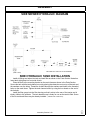
MANUAL SWITCH BOX WIRING
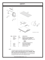
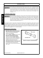
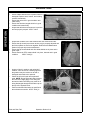
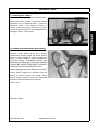
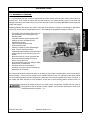
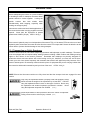
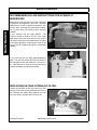
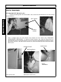
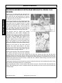
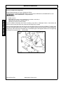
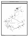
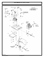
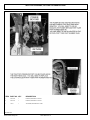
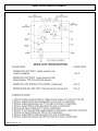
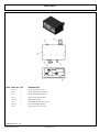
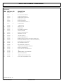
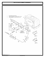
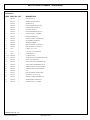
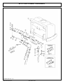
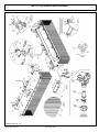
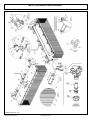
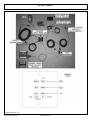
Route the green wires and the red wire (with the 10amp fuse) from the switchbox to the
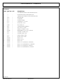
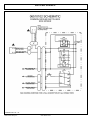
front console panel. Refer to the parts section for wiring diagram to hook up the switch
box. Cover the wires from the switch box with plastic wire wrap provided. Remove the
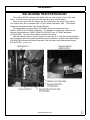
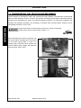
console panel under the steering wheel to access wires. Locate the neutral safety wire.
Using a test light or meter, verify this wire is the neutral safety wire. Cut the neutral
safety wire and connect the green wires from the switch box as shown in the wiring
diagram.
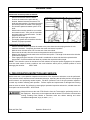
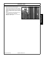
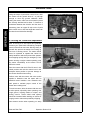
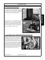
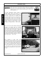
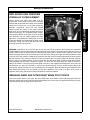
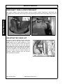
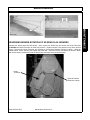
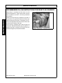
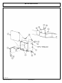
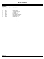
Run the white and black wire to the solenoid valve. Route the wires through the back
window with the cable control wires. Use the rubber grommet in the window to protect the
wire, and route the wire out of the cab down to the 1/4” hydraulic hoses. Follow the
hydraulic hoses through the wheel well to the front of the tractor.
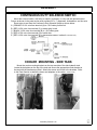
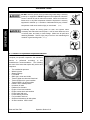
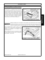
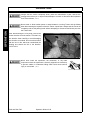
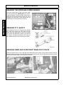
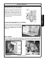
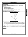
Route the Red 14ga wire, keyed hot, from the auxillary plug to the signal post of the
continuous duty solenoid. NOTE: Be certain that the power taken for the switch box is
“HOT” only when the tractor ignition is “ON”.
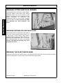
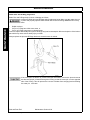
The black wire from the switchbox should be routed to the auxilary plug.
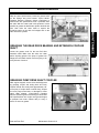
The travel lock orange and black wires from the switch box should also be covered with
wire wrap and should run with the white wire through the window. This wire will be
connected to the electronic travel lock located on the deck roll cylinder.
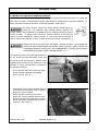
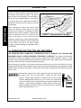
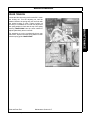
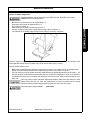
The wires from the switch box are longer than needed and should carefully cut and
spliced as required. Zip ties should be used to secure the wires to the tractor framework and
boom hoses to eliminate vibation and rubbing. (ASM-MF-0007)
Assembly Section 2-9