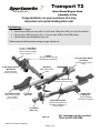
1
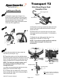
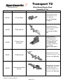
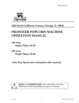
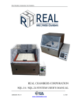
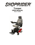
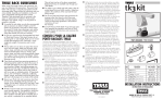
Transport T2
Hitch Mount Bicycle Rack
Assembly & Use
Congratulations on your purchase of a truly
innovative and quick-loading bike rack!
Key Features
• Fits 20”-29” wheels
• Carries up to 60lbs per tray with a 2” hitch and 160lbs total with a 3rd & 4th bike add-on
• Carries up to 60lbs per tray with a 1-¼” hitch and 100lbs total (2 Bike Max)
• Carries bikes with wheelbases up to 48”
**Please read and understand the warnings on page 9 before use.
2” or 1 ¼” Hitch Base
(Includes two anti-wobble
bolts for maximum stability
Only one bolt on 1 ¼” )
Handle
(Used to fold the rack up
and fold the rack down)
Innovative Rear Wheel
Lock Down
(Securely holds any size
tires)
4-Bar linkage Folding
Mechanism
Backbone
(Main frame for the
rack)
(Solid mechanism
prevents rack sway )
RQL Support Arm
(Provides maximum security)
Front Wheel Cradle
(Easily accommodates
20”-29” wheels
and any tire size.)
1st Position
Bike Tray
Support Arm
Wingnuts
(Easily adjustable
support arm resistance)
Adjustable brackets
(Reduces bike interference
by allowing adjustment of
pitch and offset)
2nd Position
Bike Tray
Figure A.
9490-A T2 Instruction Manual
Page 1 of 12
For customer service contact
Thule at 800-238-2388
Transport T2
Hitch Mount Bicycle Rack
Assembly & Use
To prepare your rack for installation…
Out of the box:
1. To prepare your rack for installation, remove the bolt, nut and washer from the rear linkage
bars using a ¾” wrench(see Fig A-1).
2. Swing the hitch base 180 degrees and line up the bushings in the middle hole with the rear
linkage bars(Fig A-2).
3. Replace the bolt, nut and washer and tighten(Fig A-2).
Tools Required for Assembly:
6mm Allen Wrench (included), ¾” wrench and a 15/16” wrench. NOTE: All fasteners are
pre-installed for easy assembly.
Fig A-1
2. Rear linkage Bars
2. Hitch Base
2. Middle hole
Fig A-2
3. Replace Bolt,
nut and washer.
9490-A T2 Instruction Manual
Page 2 of 12
1. Bolt, Nut and washer to
remove
Transport T2
Hitch Mount Bicycle Rack
Assembly & Use
Assembly Instructions:
Vehicle Hitch
Receiver
A) Insert hitch base into vehicle’s hitch receiver.
Fig. B.
NOTE: Assembly can be done off the vehicle
if desired. Proceed to Step 2.
C) Top Anti-wobble Hitch Bolt
B) Tighten side hitch bolt with a
15/16” wrench to 80ft-lbs for a 2”
Hitch 40ft-lbs for a 1-¼” Hitch.
C) Tighten top hitch bolt with a ¾”
wrench to 40ft-lbs.
B) Side Anti-wobble
Hitch Bolt
Hitch Base
Figure B.
D) Orange
line on
decal.
A) Slide the first bike tray oriented with the front wheel
cradle on the driver’s side of the vehicle onto the
backbone of the rack.
B) Position the tray so that the bracket lines up with the white
line on the bottom of the decal(Fig C.) and center the tray so the
center line on the side of the tray shows through the cutout in the
bracket . Fig D.
C) Tighten all 4 bolts with the 6mm
allen wrench until the lower bracket
wings touch the bottom of the spar
tube. See Fig. D These fasteners
B) Orange must be tight and should be
periodically checked with rack use.
line on
decal.
D) Repeat A-C with second bike
Figure C. - View from bottom of the rack stowed.
tray oriented with the front wheel
cradle on the passengers side.
Line the bracket up with the other
end of the decal (Fig C.) and
center it with the centerline mark.
Fig. D.
A) Insert the two plastic caps into the holes at the
end of the spar tube. Fig F.
Note: This prevents water from getting
inside the spar tube.
Figure F.
Assembly is Complete!
9490-A T2 Instruction Manual
Page 3 of 12
Figure D.
* Be sure to tighten bolts
equally to ensure a level
carrying platform.
Transport T2
Hitch Mount Bicycle Rack
Assembly & Use
Loading your Bicycle:
Green Trigger Latch
A) Rotate the support arm forward. You
should feel some resistance at first and then
the arm should rotate freely. While grabbing
the grip assembly on the support arm,
depress the green trigger and slide the hook
to the end of the support arm.
Grip Assembly
Figure G.
A) Place bike in first tray nearest the vehicle with front
wheel in the wheel cradle and rear wheel in the rear
wheel lock down.
B) While holding on to the bike with one hand rotate
the support arm up until it sits within 1” of the brake or
fork. Fig H.
C) Ratchet the arm tightly against the wheel. You
should hear a minimum of 2 clicks. Fig I.
NOTE: If you notice any bike interference with the
vehicle, please see page 5 for fit tips and
accessories.
Figure I.
Figure H.
A) Move the rear wheel lock down under the
rear axle of your bicycle. Fig J.
B) Thread the anchor end of the ratcheting strap
through the spokes and secure the anchor in the lock
down. Use the lower position for road tires and the
upper for deeper rims or mountain bike tires. Fig L.
NOTE: The slack can quickly be taken out of
the strap by pushing or pulling the strap
through the buckle.
E)
Figure J.
D)
Figure K.
B) Upper position
B) Lower position
D) Tighten the ratcheting strap against the rim by
pulling up on the silver buckle. Fig K.
E) To Release the rear wheel strap, lift the green
button and pull the strap until it is loose enough to
remove the anchor. Fig K.
Note: Larger Rim Straps are available for
very deep rims. Please see accessories on
page 8 for more information.
Figure L.
9490-A T2 Instruction Manual
Page 4 of 12
Transport T2
Hitch Mount Bicycle Rack
Assembly & Use
A) Once your bike is loaded shake the bike
to make sure the support arm is seated
correctly.
WARNING: The support arm v-notch
must be firmly seated against the tire
and brake, or fork. Failure to seat the
support arm securely may result in bike
instability. Always shake your bike after
loading to ensure the hook arm is fully
seated.
Figure M.
Folding your Bike Rack:
B) Quadrant Latch Bar Slot
A) To fold your bike rack up against your
vehicle, pull the green latch handle at the
base of the rack while gently lifting the rack
to release the latch bar. Fig N.
B) Once the square latch bar is released,
lift the rack up until the latch bar snaps into
place on top of the quadrant. Fig N.
C) If you notice any interference with
A) Latch bar
the vehicle please refer to Fit Tips on
page 5 for solutions.
Figure N.
A) To drop your rack down, remove the
safety pull pin first (Fig O.) and then pull
the latch handle to release the square
bar. (Fig N.) The rack can then be
lowered to the ground for access to the
back of the vehicle.
A) Safety pull pin
Figure O.
9490-A T2 Instruction Manual
Page 5 of 12
Transport T2
Hitch Mount Bicycle Rack
Assembly & Use
Rack Maintenance and Care
1) 4-Bar Link Folding Mechanism
•
Periodically tighten bolts in 4 bar link on the
hitch base to ensure a stable connection.(Fig
P.) You should feel some resistance when
folding the rack up and down.
1) 4-Bar Link Bolts
2) Hitch Receiver Connection
• Make sure to check and tighten the antiwobble hitch bolts periodically to ensure a
stable connection. (See Fig B, pg 2.)
3) Support Arm Rotation Friction
• Check and tighten the plastic wingnuts (See
at the base of the support arm.
The arm should rotate easily, but should not
fall under its own weight. The arm should
snap into place when stowed and should
require some effort to rotate the arm up.
Fig A., pg 1)
Figure P.
4) Cleaning your rack
•
Frequently clean the rack of dirt and road grime including wiping down the teeth on
the support arm while extended. It is especially important to clean road salt from
the rack as this can promote rust over time.
Fit Tips
1) Bike Interference with each other or with the car.
A. Pitch – Distance between bikes
•
To adjust pitch, loosen all 4 bracket bolts and slide
the tray in or out. Re-tighten bolts to secure tray.
A) Pitch
(See Step 2 on pg. 2.)
B) Offset
B. Offset – Side to Side Distance
•
To adjust offset, loosen all 4 bracket bolts and slide
tray left or right. Re-tighten bolts to secure tray. (See
Step 2 on pg. 2 for directions on tightening bracket bolts.)
Figure Q.
Note: Do not slide tray past offset limit
marks on either side of the bracket or
failure may occur. See Fig D. pg 2.
2) For ground clearance issues see Accessories on page 9.
3) Retrofitting your rack to another hitch size – 1 ¼” or 2”
•
Swap out the hitch base with the other size by removing the bottom two hitch bolts seen
in fig P at the top of the page. For part numbers on hitch assemblies see Accessories on
page 6&7. Call your dealer to purchase the proper part.
9490-A T2 Instruction Manual
Page 6 of 12
Transport T2
Hitch Mount Bicycle Rack
Assembly & Use
Part Number
260123
260125
260113
Description
Image
Use
Provides 9-½” of extension.
Allows clearance for spare tires
mounted on the rear of a car or
if hitch receiver is not mounted
flush with the bumper. Note:
This may make rack more
vulnerable to contacting the
pavement when encountering
road irregularities.
Use ONLY with Sportworks
racks.
2” Hitch extension
Provides 7-3/8” of extension.
Allows clearance for spare tires
mounted on the rear of a car or
if hitch receiver is not mounted
flush with the bumper. Note:
This may make rack more
vulnerable to contacting the
pavement when encountering
road irregularities.
Use ONLY with Sportworks
racks.
1 ¼” Hitch Extension
Hitch base mounts directly into
the riser extension. It provides
9-1/3” of extension and 5 ¼” of
rise.
2” Riser Extension
Use ONLY with Sportworks
racks.
260126
2” High Rise Hitch Base
Replaces hitch base that comes
with the rack. See pg 5 for
mounting instructions. Adds 6” of
rise. Reuses all the existing
hardware. Does not increase
extension. Best solution for
ground clearance issues.
260103
2” Hitch Base
Use this part to convert your rack
from a 1-1/4” to a 2” hitch size.
9490-A T2 Instruction Manual
Page 7 of 12
Transport T2
Hitch Mount Bicycle Rack
Assembly & Use
Part Number
260104
Description
Image
Use
Use this part to convert
your rack from a 2” to a
1-1/4” hitch size.
1 ¼” Hitch Base
See 1-1/4” load limits
on page 10.
260102
Attaches directly to the
Transport T2 2-bike rack to
carry a third bike.
3rd Bike Add-On
For use with a 2” Hitch
only.
260150
260202
Use this connector
between the 2nd and 3rd
position bike trays to
allow the 3rd and 4th trays
to fold against the first
two trays to eliminate
obstruction of view when
rack is stowed.
Fold only when rack is
up.
3rd Bike Folding
Connector
Attaches directly on the 3rd
bike add-on to carry a 4th bike.
4th Bike Add-On
For use on a 2” Hitch only.
260133
Attaches directly to Transport
T2 2-Bike Rack. Carries any
recumbent with up to a
maximum wheelbase of 63”.
Universal Recumbent
Add-On
For use on a 2” Hitch only.
9490-A T2 Instruction Manual
Page 8 of 12
Transport T2
Hitch Mount Bicycle Rack
Assembly & Use
Part Number
Description
253106
2” Locking Bolt
253105
2” Locking Bolt and
Cable
Image
Use
Lock your rack to your vehicle.
Comes with two keys.
Replaces the side anti-wobble
hitch bolt.
Lock your rack to your vehicle
and your bike to the rack.
Comes with two keys. Cable
is a 13 foot 10-gauge cable.
253108
11/4” Locking Bolt
Lock your rack to your vehicle.
Comes with two keys.
Replaces the side anti-wobble
hitch bolt.
253107
11/4” Locking Bolt and
Cable
Lock your rack to your vehicle
and your bike to the rack.
Comes with two keys. Cable
is a 13 foot 10-gauge cable.
Large Rear Wheel Lock
Down Strap
Use in place of the rear wheel
lock down ratchet strap with a
rim and tire combination
deeper than 4.5”.
260215
**The Transport T2 is a modular rack and can be configured to carry a combination of
recumbent and upright bicycles. Please contact your dealer or Sportworks Northwest, Inc.
for information on custom configurations and additional accessories.
9490-A T2 Instruction Manual
Page 9 of 12
Transport T2
Hitch Mount Bicycle Rack
Assembly & Use
Rack Dimensions
Rack in the stowed position
Rack in the deployed
position
Hitch Size A) Height
deployed
2” Hitch
6 .4 ”
1 ¼” Hitch 8.9”
B) Length
C)Length to wheel
D)Bumper clearance
deployed
hoop stowed
height of rack stowed
3 5 .3 ”
3 4 .3 ”
4 .5 ”
3 .5 ”
8 .9 ”
1 1 .4 ”
9490-A T2 Instruction Manual
Page 10 of 12
Transport T2
Hitch Mount Bicycle Rack
Assembly & Use
Instructions and Warnings you must read and understand
• Before installation, please check that your hitch receiver is properly installed per the manufacturer’s instructions, and that
all fasteners are tight.
• Do not exceed the vehicle manufacturers recommended load limits for your hitch receiver.
• Individual bike weight should not exceed 60 lbs and total weight load must not exceed 160 lbs for a 2” receiver rack.
• Individual bike weight should not exceed 60lbs and total weight load must not exceed 80lbs for a 1 ¼” receiver rack.
• Periodically check the hitch base 4-bar link bolts and make sure they are tight and secure.
• Ratchet arm teeth and ratchet grip must be kept free of dirt accumulation for proper operation.
• Sportworks racks are not intended for off-road vehicle use.
• The ratchet arm pivot clamp fasteners must be tight and in good condition. Failure in a ratchet arm pivot clamp fastener
may result in damage to the rack, bike or vehicle.
• The hook arm V-notch must be firmly seated against the tire and the bike frame. Each time the rack is loaded, the bike
should be shaken to insure positive hook seating. If the shake test feels at all loose, pull the ratchet grip to the next tooth
and re-shake to test. Failure to seat the hook arm securely may result in bike instability. Damage to the rack, bike or
vehicle may result.
• The bicycle must be properly assembled and ready-to-ride to be safely carried.
• The bicycle tires must be properly inflated. Loss of air after the ratchet has been set may result in bike instability. Damage
to the rack, bike or vehicle may result.
• Use this rack only with bicycle tires having a tread width of 3.0” or less.
• Do not load any extra length bicycles which have a wheelbase that overhangs the wheel tray. Damage to the rack, bike
or vehicle may result.
• Do not transport bicycles with attached baby seats, panniers, disc wheels or full wheel covers.
• Do not use automatic car wash systems when the rack is mounted on the vehicle.
• Sportworks cannot control the design, manufacture, or installation process for hitch adapters. We therefore limit our
liability to our product. We cannot be held liable for damage to bicycles or vehicles due to failures of adaptors converting
a 1 ¼” hitch receiver to a 2” hitch receiver and vice versa. We recommend purchasing the proper hitch base found on
page 6 and 7 in the accessories section of this manual.
• Sportworks cannot control the design, manufacture, or installation process for hitch receivers. We therefore limit our
liability to our product. We cannot be held liable for damage to bicycles or vehicles due to hitch receiver failures.
th
• Sportworks racks are not for use on 5 wheels or trailers of any kind.
For accessories, replacement parts, or warranty issues, please contact your dealer or:
THULE, INC.
42 Silvermine Road
Seymour, CT 06483
800-238-2388
www.thule.com
9490-A T2 Instruction Manual
Page 11 of 12
Transport T2
Warranty
Hitch Mount Bicycle Rack
Assembly & Use
This warranty stated below is a LIMITED WARRANTY under the definition thereof set forth in the Magnuson-Moss
Warranty Federal Trade Commission Improvement Act, USC S2301-12
Limited Warranty: Sportworks products (Product) are warranted to the original purchaser to be free from defects in
material and workmanship for a period of ONE YEAR and will be replaced without charge upon inspection by Sportworks
at the factory disclosing no misuse or alteration which, in the judgment of the manufacturer, has affected the condition of
or operation of the product. This is the extent of liability under this warranty and, upon the expiration of the applicable
warranty period, all such liability shall terminate.
Warranty Exclusions: We do not warrant Product against normal wear and tear, unauthorized modification or
alterations, improper use, improper maintenance, accident, misuse, negligence, damage, or if the Product is used for a
purpose for which it was not designed. In addition, this Product is not warranted for use on any commercial and/or “for
hire” vehicle. This warranty gives you specific legal rights and you may also have other rights which vary from state to
state. Except as expressly stated in the Warranty, we shall not be liable for direct, indirect, incidental or other types of
damages arising out of, or resulting from the use of the Product. This Warranty is in lieu of all other warranties, express or
implied including, not limited to, implied warranties of merchantability or fitness for a particular purpose (some states do
not allow the exclusion of limitation or incidental or consequential damages or allow limitations on the duration of an
implied warranty, so the above exclusions may not apply to you.)
Sportworks products are designed and assembled in the USA.
US Patent 5,692,659 and other Patents Pending
© 2002, 2003, 2004, 2005
No portion of this document may be reproduced without the express written consent of Sportworks Northwest, Inc.
THULE, INC.
42 Silvermine Road
Seymour, CT 06483
800-238-2388
www.thule.com
9490-A T2 Instruction Manual
Page 12 of 12