1
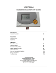
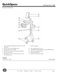
USDT 2004B Installation and User’s Guide Introduction General Information 2 Installation Collector Sensor 3 Control Box 5 Power Connection 6 Display Window 6 Operation Basic Operation of Digital Display 6 Programming the Temperature Range 8 Manual Operation Mode 9 Troubleshooting 10 Thermo Technologies 5560 Sterrett Place • Suite 115 Columbia, Maryland 21044 Phone 410.997.0778 • Fax 410.997.0779 e-Mail [email protected] Basic Revision 8, January 2006 Introduction Note: The information supplied in this manual is for guidance only - no part of this may be used for any agreement, whether express or implied, or to form any contract. Thermo Technologies reserves the right to change specifications without prior notice. U SDT 2004B is a powerful temperature differential control unit. It uses two temperature sensors to control a simple solar water heating system; one sensor measures the temperature of the solar collector whilst the second sensor measures the temperature at the bottom of the tank. The control unit has the following basic functions: • • • • • • 2 inputs for temperature sensors Hi/Low adjustable factory-set temperature programming o o Adjustable (4.1 F to 99 F) temperature difference ?T Manual override of pump for system testing Digital display of all parameters System status and diagnostic displays Operation The controller uses two sensors. One sensor (S1 in diagram) monitors the collector temperature whilst the other sensor (S2) monitors the temperature at the bottom of the storage tank. The solar loop circulation pump runs while the collector temperature S1 exceeds the tank temperature by an adjustable temperature difference diff. To avoid overheating, the circulation pump stops if the tank temperature reaches the adjustable high limit (TMAX) temperature. The pump A1 runs only when the temperature at the collector sensor location S1 is higher than the return temperature at location S2 by at least diff (?T). The pump stops if diff is less than the preset value or, when the temperature at location S2 has reached the TMAX : A1 (ON) only when S1 > (S2 + diff) & S2 < T max 2 A1 S2 INSTALLATION Note: This installation procedure is for guidance only, and the installer should verify its suitability. Make sure that the solar system is physically installed, manually tested, and ready for controlled operation. T he following safety precautions is strongly recommended: 1. Before attempting to install and operate the unit read this instruction manual carefully. 2. Only suitably qualified personnel should carry out installation and required maintenance. 3. It is recommended that the unit be connected to the power supply via an on/off switch or plug. 4. WARNING: When the unit is connected to the 115-volt power supply and the cover is opened, high voltage circuits will be exposed. When installing the unit, all required connections should be completed and the cover attached to the controller box before turning the power on. Ensure that all connections are secure. If any maintenance work is required isolate the unit from the power supply before removing the cover. Never leave the unit unattended if the cover has been removed and the power supply is connected. 5. Do not exceed unit ratings of 3.15 amps (1/6 HP or 245 Watts). 6. It is advisable to route power cables away from sensor cables. S ensor installation: Temperature sensors may be installed with fluid lines by mounting in a well or strapping it to the piping directly. For the system to function correctly, it is essential that the sensors are located and installed properly. Sensors must be well insulated in order to prevent them from being influenced by the ambient temperature. When used outdoors, water must not enter the immersion sleeves. Exposure to moisture (e.g. condensation) can diffuse through the cast resin and damage the sensor. 3 l Collector sensor (red cable with protective terminal box): Either push into a thermowell, (sensor pocket), which is soldered or riveted directly to the manifold (vacuum tubes). Alternately, strap the sensor to the collector outlet pipe or the absorber (flat plate collectors) that projects from the collector housing. Ideally, house the collector sensor (encased in a suitable sensor pocket) into a T-piece on the collector return outlet. Protect the sensor cable from UV and moisture. l Return (tank) sensor (white cable): The sensor required for the solar loop return is installed in the lower part of the storage tank. If there is no provision for this tank sensor, push the sensor beneath the insulation – keeping it close to the inner tank wall at the desire tank location. For external heat exchangers, the tank sensor should be installed with an immersion sleeve in the return leg (cold side) of the heat exchanger. In tanks with integrated heat exchangers, the sensor pocket should be fitted at the exchanger's return to the collector. l Sensor cable extension: Sensor cables (22/4 AWG telephone cable, you need only two wires of 4) can be extended up to 150 ft. A connection between the sensor and extension can be established as follows: Cut the supplied heat -shrinkable tubing to desired length (about ½ ”). Slide tubing over one end of wire to be sliced (after removing enough outer insulation to accept the tubing). Splice the wire and slide tubing over the splice. Heat gently all around until tubing shrinks tight. Slide larger tubing (about ¾ “) over the entire completed splice. Heat gently all around until tubing shrinks tight. This connection can then be drawn gently into the pipe work. Only two of the wires are required for the sensor cable; the other two wires are spare wires. Caution: Do not overheat the tubing! Remove heat as soon as the tubing shrinks tight, as material will continue to shrink. With flame source, use even back and forth motion all around tubing. A heat gun may be used, if available. Let tubing cool for maximum strength. C ontroller unit installation: For viewing comfort, the controller unit should be positioned at eye level. For optimum longevity, avoid extremes of temperature in the placement of electronic equipment. In addition, avoid heavy electrical loads, switches or contactors as these may cause electrical and electromagnetic interference with the unit (when switched on or off). 4 Undo the screw at the top of the housing. The control electronics are mounted on the enclosure cover. The controller enclosure can be screwed to the wall with cable entry grommets pointed downwards. Use the supplied plastic bridges to secure power and sensor cables. Base of the unit to be mounted at eye-level and wired as shown above Caution: Controller wiring should only be done when the unit is not energized. It is possible to damage the control unit if it is assembled under voltage. Miniaturized terminal blocks are used for making wiring connections. The wire is held in place within the terminal with screw that provides excellent contact without damage to the wire. Sensor Cable Connection: Use up to an 18 AWG stranded wire to connect the sensor cables to the unit. The S1 terminal should be connected to the collector sensor (higher temperature); the S2 terminal is designated for the tank sensor (lower temperature). The S3 terminal is reserved for advanced usage and should remain vacant for the basic program. 5 P ower Connections: A small blade screwdriver may be used to fasten miniaturized terminal block screws while the corresponding wire is inserted. NOTE 1: Always disconnect the controller from power supply before opening the housing. NOTE 2: The controller should be properly grounded. Flexible wires, 18/3 AWG (gauge/conductor) simplify connection to the terminals. The power terminal block will accommodate wire sizes to 14 AWG. All other connections should be secured and adequately tightened, as loose power connections will over-heat, and may cause fire. NOTE 3: It is important that the specified output loads (245 Watts) are not exceeded. Where these loads expect to exceed, external relays must be used. It is good practice to install a switch to disconnect the controller and pump from power. Always keep power cables away from sensor cables and other low voltage signal cables. NOTE 4: To protect against lightening damage, the system must be grounded according local regulation. Sensor failures due to the weather or electrostatic are mostly due to poor grounding. BASIC OPERATION OF DIGITAL DISPLAY Y our controller displays requested information one at a time. The unit display window has three lines to inform you about the system's status, unit of displayed parameter and its value. Upper Line Display Center Line Display Lower Line Display Symbolic display of sensor location, reading unit, and operation domain Sensor ID and its reading in normal mode (user interface window) Set-point indicator that illuminates only during programming mode ð Push selection key once to move to the next selection; or increase the selected parameter by one unit. ï Push selection key once to move to the previous selection; or decrease the selected parameter by one unit. 6 ò Push selection key once to enter the advanced (Par or *Men) mode. Once in selected mode, press one more time to select the parameter in that mode. Selected parameter blinks allowing the user to modify it. You can modify the selected parameter while the middle window blinks by pressing the ï or ð key. ñ Push selection key once to accept selection (blinking stops showing the new set-point steady) or go back to the previous selection. (*) USDT 2004B does not support “Men” mode operation. Use selection keys ïð during normal system operation to display the desired parameter: T1 xxx T2 xxx T3 250 XX xxx YY xxx ZZ xxx GAL 60 o Collector temperature in F o Tank temperature in F o Displays a fixed reference temperature of 250 F. Collector power in [kW] – amount of energy collector is producing Energy collected in [MWh] Energy collected in [kWh] Flow rate [gallon/h] – a fixed rate of 1.0 gpm ex factory Example: Following chart displays system temperatures At the upper text line , the icon for the text is always displayed. Program symbol is displayed during the setting of parameters at the lower text line. In addition, an arrow icon > is displayed while pump is running. For Programming - Pressing the selection key ð several times allows you to enter into the program mode (Par). Push selection key ò once to enter the program mode. 7 Par Using the navigation key ^_ allows you to select the desired parameter while you are in the program mode. Press the selection key ò once to select the parameter in the window. Selected parameter blinks allowing you to modify it. You can modify the selected parameter while the middle window blinks by pressing the ï or ð key. The unit accepts the new value by pressing the ñ key once. RUV 2.0 – This display shows the software revision number. NR O – This indicates the USDT 2004B employment as a basic solar hot water heating controller. PROGRAMMING THE TEMPERATURE RANGE o o USDT 2004B is factory set at T2 > 160 F PUMP OFF, T2 < 150 F PUMP ON. The user may program a different temperature range (hysteresis bandwidth) if required. In this case, there are two temperatures that should be entered: Tank Overheating Protection User can program hysteresis (temperature range for output control) by using max? and max=. For max?1 max=1 Pump stops above tank temperature (T2) Pump runs again below this set point (T2) Temperature Differential Adjustment diff=1 Pump runs when temperature difference between collector T1 (collector) and T2 o (tank) exceeds this value. Factory setting is 15 F. Consult your collector manufacturer for the recommended value. diff?1 Pump stops when temperature difference between collector T1 (collector) and T2 o (tank) reaches this value. Factory setting is 7 F. Consult your collector manufacturer for the recommended value. 8 Manual Operation Mode This mode allows the user to manually turn the pump on or off. AUTO The above display indicates that the unit is working in automatic mode. The o pump starts at a temperature difference of 15 F and runs as long as ? T is o above 7 F. The B symbol appears in upper display line next to the collector symbol while the pump is running. User can switch to manual mode by pressing ò key. By pressing ð key while centerline blinks, a hand symbol G in lower line shows manual operation. Pressing ð one more time lets you turn the pump ON or OFF. By pressing ñ key you change the pump operation. S ensor Designation – The factory-preset sensor is the thermistor (KTY) type. The KTY tank sensor, white wire, should be used in a conditioned environment and will not be o permanently damaged up to 360 F. S1 S2 Sensor 1 (collector outlet) Sensor 2 (collector inlet or bottom of the tank) Sensor wires can receive electromagnetic pulses, which can result in a wrong temperature reading. The USDT 2004B reads sensor values every 50 ms. It can bundle several readings and process their average. The impedance characteristics of the USDT 2004B sensors (temperature dependencies) are represented in the following table: T R(KTY) 0 1630 10 1772 20 1922 25 2000 30 2080 40 2245 9 50 2417 60 2597 70 2785 80 2980 90 3182 100°C 3392 Ω T roubleshooting In general, all of the settings in the menus Par and Men and the terminal should first be checked if there is a malfunction. Malfunction, but "realistic" temperature values: • • • • Check program number. It should be “0” (zero) for 2004B unit. Check the switch-on and switch-off thresholds and the set differential temperatures, page 8. Have the thermostat and differential thresholds already been reached? Can the pump (output) be switched on and off in manual mode? If a forced pump “ON” and “OFF” lead to the appropriate reaction at the output, the unit is certainly in order. Are all of the sensors connected to the right terminals? Heat up the sensor using a cigarette lighter and watch the display. Incorrect display of temperature(s): • • -999 sensor short -circuit 999 no sensor reading - (open loop) interruption do not necessarily mean a material or terminal error. Overheating protection: The Circulation pump may not be powerful enough to circulate the heat transfer fluid in the solar loop with air pockets. To protect the pump, USDT 2004B will take over the normal operation after the temperature decreases to an acceptable working temperature. The sensor can also be checked without a measuring instrument by connecting the presumed defective sensor to a terminal that works and checking the display. The resistance measured by an ohmmeter should have the impedances shown in page 9. The settings of the parameters and menu functions ex works can be restored any time by pressing the down arrow (enter) while powering the controller. The sign that appears for three seconds on the display is RESTOR for load factory settings. If the system is not in operation while connected to the power supply, the 3.15A quick-blowing fuse that protects the control system and the output should be checked and exchanged if necessary. As the programs are constantly being improved, there may be a difference in the sensor and program descriptions. Only the enclosed manual (identical serial number) applies for the equipment supplied. The program version for the manual must correspond to the equipment version. If the control system is found to be malfunctioning despite the checks described above, please contact your retailer or Thermo Technologies directly. The cause of the error can only be determined if the settings of the unit is known. The schematic diagram of the system in question is a great help to isolate the potential problem. 10