1
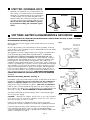
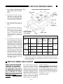
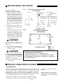
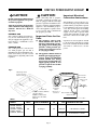
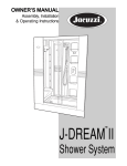
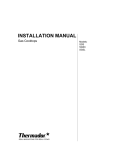
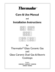
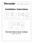
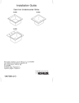
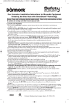
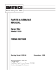
INSTALLATION INSTRUCTION MANUAL
MODELS: GGS30, GGS36, GGS365, GGN30, GGN36, GGN365,
SGS30, SGS36G, SGN30, SGN36G
Thermador® ExtraLow™ and Traditional Series Cooktops
PLEASE READ ENTIRE INSTRUCTIONS BEFORE PROCEEDING.
IMPORTANT: LOCAL CODES VARY. INSTALLATION, ELECTRICAL CONNECTIONS
AND GROUNDING MUST COMPLY WITH ALL APPLICABLE CODES.
IMPORTANT: Save these instructions for the Local Electrical Inspector’s use.
INSTALLER: Please leave these Installation Instructions with this unit for the owner.
OWNER: Please retain these instructions for future reference.
Power Supply: 120 volts, 15 Ampere,
60 Hz., Natural Gas - 5 inch water
column, Propane Gas - 10 inch water
column.
WARNING: Disconnect power before
installing or servicing. Before turning power ON, be sure that all controls are in the OFF position.
IMPORTANT INSTALLATION INFORMATION
Warning: Improper installation, adjustment, alteration, service or maintenance can cause injury or
property damage. Refer to this manual. For assistance or additional information consult a qualified
installer, service agency, manufacturer (dealer) or the
gas supplier.
This appliance has been tested in accordance with
ANSI Z21.1Current Issue, Standard for Household
Cooking Appliances (USA) and in accordance with CAN
1.1-M81 Domestic Gas Ranges (CANADIAN).
Check your local building codes for the proper method
of installation. In the U.S., if there are no applicable local
codes, this unit should be installed in accordance with the
National Fuel GAS Code #Z223.1-1990, and the National Electrical Code
ANSI/NFPA No. 70 Current Issue. (In Canada, installation must be in
accordance with the CAN 1-B149.1 and .2 – Installation Codes for Gas
Burning Appliances and/or local codes.)
Be sure the unit being installed is correct for the type of gas being used.
The cooktop is shipped from the factory for use with natural gas. Conversion for use with propane gas can be made using a kit, Model NLPKIT5,
P/N 35-00-622. A qualified technician or installer can convert the cooktop.
This kit includes instructions for adjusting valves and regulator and
contains new burner jets.
This appliance is equipped with an intermittent/interrupted ignition
device.
Page 2
!
▲
CAUTION:
(1) When connecting the
unit to propane gas make
certain the propane gas
tank is equipped with its
own high pressure regulator in addition to the
pressure regulator supplied inside this unit. The
maximum gas pressure to
this appliance is not to
exceed 14.0 inches water
column from the propane
gas tank regulator.
Do not attempt to connect
propane gas without first
installing conversion kit,
Model NLPKIT5, P/N 3500-622. A qualified service
technician or installer can
convert the cooktop.
(2) This unit is designed
as a cooking appliance.
Based on safety consideration never use it for
warming or heating a
room.
TABLE OF CONTENTS
Important Installation Information . . . . . . . . . . . . 2
Step One: Before You Begin . . . . . . . . . . . . . . . . . . . 3
Step Two: Overhead Hood . . . . . . . . . . . . . . . . . . . . .4
Step Three: Electrical Requirements . . . . . . . . . . . . . . . 4
Step Four: Prepare Cabinet. . . . . . . . . . . . . . . . . . . . 5
Step Five: Install the Cooktop . . . . . . . . . . . . . . . . . . 6
Step Six: Power Supply Hook-up. . . . . . . . . . . . . . . . .6
STEP ONE: BEFORE YOU BEGIN
Get the Best Venting
Performance
Fig. 1
Points to consider are:
•
•
123
123
123
123
123
123
123
123
123
123
123
123
123
123
123
123
123
123
123
123
123
123
123
123
123
123
123
123
123
123
123
123
123
123
123
123
123
123
Wall
123
123
123
123
123
123
123
123
Thermador recommends use of a
ducted hood over this cooktop.
Minimize cross drafts that can
be created by adjacent open
windows, doors, air conditioning, heating vents, recessed
ceiling lights, etc.
Cabinet Considerations
•
This unit is designed for
installation in a countertop
near adjacent walls and projecting surfaces constructed of
combustible materials. There
must be a minimum clearance
of 30 inches between the top of
the cooking surface and the
bottom of the unprotected wood
or metal cabinet; or 24 inches
when bottom of wood or metal
cabinet is protected by not less
the 1/4" of flame retardant
material covered with not less
than No.28 MSG sheet metal,
0.015 inch stainless steel,
0.024 inch aluminum or
copper. (See Figure 1.) The
minimum horizontal distance(s)
from the side and back edge of
the unit to adjacent vertical
combustible walls are as
follows: Left side wall - 3
inches; right side wall - 3
inches, rear wall - 1 inch.
Cooktops installed over a CT130
oven require adequate air inlet to
the cabinet below. This is to
prevent simmer flame outage when
operating the oven. Provide
GAS INSTALLATION GUIDE
Cabinet Depth from
Back Wall is 13" Max.
Hood Depth 24" Max.
30" Min.
centered over
Cooktop
Models GGS30,
SGS30,GGN30 &
SGN30
3" Min. - no
upper cabinets
30" min.
18" Min.
36" Min.
centered over
Cooktop
Models GGS36/
365,SGS36G,
GGN36/365 &
SGN36G
3" Min. - no
upper cabinets
123
123
123
123
123
123
123
123
123
123
123
123
123
123
123
123
123
123
123
123
123
123
123
123
123
123
123
123
123
123
123
123
123
123
123
123
123
123
Wall
123
123
123
123
123
123
123
123
Dimensions are to Combustible Materials
and are minimum requirements
approximately 10 in.2 opening in
the toe kick area or other cabinet
area.
•
Instructions are based on
Standard American cabinets
36" high x 24" deep.
Maximum depth of cabinets
installed above cooking surface of
the cooktop is 13 inches.
Maximum depth of drawer under
unit is 15 inches.
Page 3
◆!
CAUTION:
All measurements given have
to be precisely followed. If
nonstandard cabinets are
used care should be taken to
alter dimensions accordingly.
STEP TWO: OVERHEAD HOOD
•
Thermador recommends use of a ducted hood over
this cooktop. For wall-mounted hood installations,
Thermador recommends that the hood should have
a certified rating of no less than 350 CFM on the
highest setting. The exhaust hood must be installed
according to instructions furnished with the hood.
Observe all local codes and ordinances governing residential cooking and ventilation requirements.
HOODS
ISLAND
WALL
STEP THREE: ELECTRICAL REQUIREMENTS & GROUNDING
THIS APPLIANCE MUST BE CONNECTED TO A RECEPTACLE ON A CIRCUIT RATED 120 VOLTS, AC 60HZ., 15 AMPERE
Recommended Grounding Method
Fig. 2
Three Prong
Receptacle
➝
Receptacle Box
Cover Plate
➝
Three Prong Plug
Fig. 3
Two Prong
Receptacle
Ground
Wired➝
If installing a properly grounded wall receptacle is impossible at the time of
installation, consult your local electrical inspector for permission to
connect a temporary adapter (with polarized blades) which could be
plugged into your present 2-wire receptacle. This is not recommended.
Ground
Wire
Three Prong
Adaptor
Grounded Cold
Three
Water Metal Pipe
Prong
Plug
➝
➝
If this is done, you must attach the lug and/or the green adapter wire to
the receptacle cover plate screw. Ground from it to a grounded metal cold
water pipe,* see Fig. 3. DO NOT GROUND TO A GAS SUPPLY PIPE.
You must permanently ground the adapter before connecting the appliance to the power supply.
➝
Alternate Grounding Method - See Fig. 3.
Cover
Plate ➝
➝
This appliance is factory equipped with a power supply cord with a threeprong grounding plug (with polarized parallel blades). IT MUST BE
PLUGGED INTO A MATING GROUNDING TYPE RECEPTACLE, CONNECTED TO A CORRECTLY POLARIZED 120 VOLT CIRCUIT. Improper
polarization will cause malfunction (such as continuous sparking of the
burner igniters) and may damage this appliance and could create a
condition of shock hazard at the igniter of each burner. If the circuit does
not have a grounding type receptacle, it is the responsibility and obligation
of the installer or user to have the existing receptacle changed to a properly grounded and polarized receptacle in accordance with all applicable
local codes and ordinances by a qualified electrician. In the absence of
local codes and ordinances, the receptacle replacement shall be in accordance with the National Electrical Code. THE THIRD GROUND PRONG
SHOULD NOT UNDER ANY CIRCUMSTANCES, BE CUT OR REMOVED.
See Fig. 2.
➝
Observe all governing codes and ordinances when grounding. In the absence of these codes or ordinances observe National Electrical Code ANSI/
NFPA No. 70 Current Issue.
➝
Always disconnect electric supply cord from wall outlet before servicing
this appliance.
Fig. 4
No. 4 Wire
➝
➝
CAUTION: Attaching the adapter ground wire to the wall receptacle
cover screw does not ground the appliance unless the cover screw is
grounded through the house wiring.
If there is any doubt as to whether the wall receptacle is properly
grounded, the customer should have it checked by a qualified electrician.
Page 4
➝
➝
➝
Cold water pipe must have metal continuity to the electrical ground and
not be interrupted by plastic, rubber or other electrically insulating
connectors (including water meter or pump) without adding a jumper wire
at these connections. See Fig. 4.
Clamp
Metal Clamp
Water
Pipe
Meter
STEP FOUR: PREPARE CABINET
1.
See Cabinet Considerations
under Step One: Before You Begin,
CABINET AND COUNTERTOP DIMENSIONS
Fig. 5
page 3.
1" Min. to Wall
21-3/4"
"B"
2.
3.
4.
5.
Instructions are based on Standard American cabinets 36" high
x 24" deep. If nonstandard cabinets are used care should be taken
to alter dimensions accordingly.
3" Min. to Wall
All cutout dimensions given in
figure 5 have to be precisely followed.
Plan the installation of the unit so
that the power cord, gas shut-off
valve and gas pressure regulator
are accessible from the front of
cabinet. If a drawer is installed,
directly under the cooktop, its
depth should be no greater than
15 inches.
This unit has been Design Certified for installation in countertop
near adjacent walls and projecting surfaces constructed of combustible materials. The minimum
horizontal distance from the back
edge of the cooktop to adjacent
vertical combustible wall, and
minimum horizontal distance
from front edge of cooktop to front
side of countertop is 1 inch. The
minimum horizontal distance
from the sides of the cooktop to
the adjacent vertical combustible
walls are as follows: left and right
side walls is 3 inches and to the
rear wall is 1 inch.
3" Deep
from Top
of Counter
"E"
3" Min. to Wall
"F"
1/8" Min. Clearance
from Cooktop Edge
to Start of Radius
3" Min. to Wall
1" Min.
COUNTERTOP CUT-OUT DIMENSIONS
COOKTOP DIM. REPLACEMENT
MODELS
NEW
INSTALLATION
EXCEPT
OVER CT130
OVEN
NEW*
INSTALLATION OVER
CT130
OVEN
COOKTOP
SOLID**
WIDTH “B”
SURFACE
MATERIAL
26-1/2" min.
29-7/8" max.
27"
29-3/4"
29-3/4"
18-5/16" min.
20-15/16" max.
19"
20"
20"
GGS36/365, E
GGN36/365,
33" min.
35-1/8 max.
33-1/2"
35"
35"
SGS36G &
SGN36G
18-5/16" min.
20-15/16" max.
19"
20"
20"
GGS30,
GGN30,
E
SGS30 &
SGN30
F
F
30-3/4"
36"
*
Cooktops installed over CT130 ovens require larger cutouts (see Fig. 5).
**
Solid surfacing material countertops such as Surell™ and Corian® require
larger cutouts and special installation specified in cooktop securement
section, (see Step 5).
STEP FIVE: INSTALL THE COOKTOP
APPLY TAPE AND SECURE
COOKTOP TO COUNTER
A foam tape is provided to seal
the cooktop edges to the countertop, shown in Fig. 6. Apply tape to
the cooktop glass on the perimeter
prior to installing the cooktop.
Position the tape to the glass on
Models GGS & GGN and to the
burner box on Models SGS & SGN
(as shown).
The cooktop may be secured to
the countertop using hold-down
brackets provided. Attach
clamps to the burner box using
washer andscrews provided prior
to inserting cooktop into the cutout. Insert cooktop into cutout.
Adjust hold down brackets to
desired position and tighten
screws to burner box. Insert
clamping screw into clamp and
secure cooktop to counter top,
Page 5
see Fig. 6 on Page 6.
Counter tops made from SOLID SURFACING MATERIALS, such as Surell™
and Corian®, require special cut-out
preparation and installation procedures.
Follow the manufacturers guidelines in
preparing the cut-out to the dimensions
noted in Fig. 5, above.
Continued on Page 6
STEP FIVE: INSTALL THE COOKTOP
Continued from Page 5
Fig. 6
ATTACHING HOLD DOWN BRACKETS & FOAM
TAPE INSTALLATION
Install the cooktops as follows:
a)
b)
c)
Foam Tape (seal)
PORCELAIN TOP
Wooden Block
Wooden Block
(to be used with solid
surfacing material, i.e.
Surell and Corian)
(to be used with solid
surfacing material, i.e.
Surell and Corian)
Clamp
Burner Box
Burner Box
Adjusting
Screw
Clamp
GGS & GGN
GG
Adjusting
Screw
Attach clamps to the burner box
using washer and screw provided,
see Fig. 6.
Center cooktop in center of cutout to insure adequate clearance
between the burner box and
counter top edge. (A light pencil
mark along center of front edge
and side edge of cooktop and
counter will aid positioning the
cooktop in the center).
Foam Tape (seal)
GLASS TOP
Burner Box
Apply heat reflective tape (such
as Scotch® Aluminum Foil Tape
#425 or #427) around the cutout so that it folds over on the top
and sides. DO NOT WRAP THE
TAPE UNDERNEATH THE COOKTOP. Be sure the tape extends
beyond the outermost flange of
the cooktop. All corners should
also be covered with tape, see
Fig. 7.
Adjusting
Screw
SGS & SGN
Clamp
COUNTER CUTOUT Shows location of Aluminum
Reflective Tape
Fig. 7
CAUTION
Avoid scratching or chipping the
edges of the cut-out with cooktop
burner box.
d)
Adjust and tighten clamps to the
burner box. Insert clamping
screw into clamp.
CAUTION
Insert a wooden block between the
end of the screw and the bottom of
the SOLID SURFACING MATERIAL
countertop. Do not overtighten
clamping screw, see Fig. 6.
For Massachusetts Installations: !
1. Shut-off valve must be a “T” handle gas cock.
2. Flexible gas connector must not be longer than 36 inches.
3. Not approved for installation in a bedroom or a bathroom
unless unit is direct vent.
e) Trim excess aluminum tape around
cooktop flange.
STEP SIX: POWER SUPPLY HOOKUP
GAS CONNECTION
The gas inlet to the unit is located at the right rear of rough-in box. (See
Fig. 8). After installing a gas shut-off valve in an easily accessible location
under the unit (see Fig. 9), install the gas pressure regulator (supplied) to
manifold pipe using pipe dope on threads of manifold pipe. To prevent
possible damage to the gas pressure regulator, install it after the rough-in
box is in its permanent position. Proceed with gas connection.
Connect the gas supply line to the unit pressure regulator using a
1/2" flex gas line connector between wall shut-off valve and pressure
Page 6
regulator (see complete procedure
at Fig. 9).
Always use pipe dope on the pipe
threads and be careful not to apply
excessive pressure when tightening
the fittings.
STEP SIX: POWER SUPPLY HOOKUP
CAUTION:
CAUTION:
Do not attempt any adjustment of
the pressure regulator, except conversion to propane.
When connecting unit to propane
gas make certain the propane gas
tank is equipped with its own high
pressure regulator in addition to the
pressure regulator supplied with the
appliance. The maximum gas pressure to the appliance regulator is not
to exceed 14.0" water column from
the propane gas tank.
Turn on gas and check supply line
connections for leaks using a soap
solution. Do not use a flame of
any sort.
NATURAL GAS
The cooktop is shipped from the factory for use with natural gas only.
The gas supply to the appliance regulator must be a minimum of 6.0"
water column.
PROPANE GAS
!
The cooktop must be converted for
use with propane gas use Kit #
NLPKIT5 P/N 35-00-622 which contains new burner jets (orfices) and
instruction for adjusting valves and
regulator.
Important Notes for Gas
Units:
(a) The appliance and its individual shutoff valve must be
disconnected from the gas supply piping system during any
pressure testing of that system at test pressures in excess
of 1/2 psig (3.5 kPa).
Important Electrical
Connection Instructions
This appliance is now ready for connection to the properly grounded and
polarized three-prong wall receptacle
located within reach of 6-foot supply
cord. The circuit required is 15 Amp,
120Volt, 60 Hz. Before connecting
supply cord to wall receptacle make
certain that wall shut-off valve and
all burner controls are in “OFF” position.
Operation of electric igniters should
be checked after unit and gas supply
have been carefully checked for leaks
and unit is connected to electric
power.
(b) The appliance must be isolated
from the gas supply piping system by closing its individual
manual shutoff valve during
any pressure testing of the gas
supply piping system at test
pressures equal to or less than
1/2 psig (3.5 kPa).
Fig. 9
Fig. 8
Opening for Gas
Connection &
Electrical Cord
Rough-In Box
1/2" Female
Pipe Threads
Supply Cord
120 V
2"
C
L of Cutout
11-5/8" for GGS30, GGN30,
SGS30 & SGN30
14-7/8" for GGS36/365,
GGN36/365, SGS36G &
SGN36G
Table 1
MODEL
GGS30, GGN30
GGS36, GGN36
GGS365, GGN365
SGS30, SGN30
SGS36G, SGN36G
Pressure
Regulator
Shows
Direction of
Gas Flow
CL Of Wall
Receptacle
Gas Shut-Off Valve
Gas Stubout
Cabinet Floor
VOLTS
CIRCUIT REQUIRED
HZ.
120
15 Ampere
60
Page 7
Flex Gas Line
GAS
MANIFOLD PRESSURE
Natural
5 Inch Water Column
Propane
10 Inch Water Column
Thermador is a leading manufacturer of Convection Micro Thermal Ovens, Convection Thermal Ovens,Thermal Electric Ovens,
Warming Drawers, Free-Standing and Slide-In Ranges, Steel Gas ExtraLow® Cooktops, Steel Gas Cooktops, Glass Gas ExtraLow
Cooktops, Glass Gas Cooktops, Glass Ceramic Gas Cooktops, Glass Ceramic Dual-Fuel Cooktops, Glass Ceramic All-Radiant
Cooktops, Glass Ceramic Halogen Cooktops, Electric Cooktops, Professional® All-Gas Ranges and Cooktops, Professional
Dual-Fuel Ranges, Cook'n'Vent® Downdraft Ventilation System, Hoods,Ventilators, Housings, Dishwashers and Char-Glo® Outdoor
Barbecues. Specifications are for planning purposes only. Refer to installation instructions and consult your countertop
supplier prior to making counter opening. Consult with a heating and ventilating engineer for your specific ventilation requirements.
For the most detailed information, refer to installation instructions accompanying product or write Thermador indicating the
model number.
Thermador reserves the right to change specifications or design without notice. Some models are certified for use in Canada.
Thermador is not responsible for products which are transported from the United States for use in Canada. Check with your
local Canadian distributor or dealer. Thermador, 5551 McFadden Avenue, Huntington Beach, CA 92649.
5551 McFadden Avenue, Huntington Beach, CA 92649 • 800/735-4328
ECO 14028 • 20-02-275I • © BSH Home Appliances Corp. • Litho in U. S. A. 4/01
Page 8