1
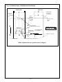
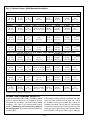
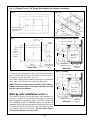
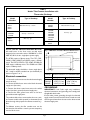
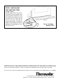
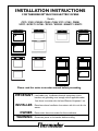
INSTALLATION INSTRUCTIONS
FOR THERMADOR® BUILT-IN ELECTRIC OVENS
Models:
C272 / C302 / CM302 / CJ302 / CJ301/ C271 / C301 / CM301
SC272 / SCD272 / SC301 / SC302 / SCD302 / SMW272 / SM272
UPPER OVEN
LOWER OVEN
UPPER OVEN
COOK
TIME
STOP
TIME
1
2
3
TIMER 1
TIMER 2
4
5
6
BROIL
SELF
CLEAN
BROIL
SELF
CLEAN
CLOCK
OVEN
LIGHT
7
8
9
CONVECTION
CONVECTION
ROAST
CONVECTION
CONVECTION
ROAST
BAKE
OFF
BAKE
OFF
COOK
TIME
STOP
TIME
1
2
3
TIMER 1
TIMER 2
4
5
6
BROIL
SELF
CLEAN
CLOCK
OVEN
LIGHT
7
8
9
CONVECTION
CONVECTION
ROAST
BAKE
OFF
0
0
Please read this entire instruction manual before proceeding.
IMPORTANT:
Local codes vary. Installation, electrical connections, circuit
breakers and grounding must comply with all applicable codes.
Save these instructions for the Local Electrical Inspector's use.
INSTALLER:
Please leave these Installation Instructions with this unit for the
owner.
OWNER:
WARNING:
Please retain these instructions for future reference.
Disconnect power at the breaker before installing.
TABLE OF CONTENTS
STEP 1: UNPACKING ............................................................................................ 2
STEP 2: CABINET PREPARATION ..................................................................... 2
STEP 3: ELECTRICAL INSTALLATION ............................................................. 6
STEP 4: INSTALLING THE OVEN ...................................................................... 7
STEP 5: INSTALLING THE BOTTOM TRIM .................................................... 8
STEP 1: UNPACKING
Fig. 1 Oven Base Attachment
Cut the bands from the carton. Carefully remove the
carton, fillers and all packing material. Included with
your new Thermador oven are the following:
Number of Racks Per Oven Model
C272 / C302 / CM302
SCD272 / SCD302
SC272 / SC302
CJ302
SC301 / C271 / C301 / CM301 / SMW272 / SM272
CJ301
6
6
5
4
3
1
Shipping base skid
Remove Screws 4 places
One 2-Piece Broiler Pan (Excluding CJ 301)
Care & Use Manual
Installation Instructions
Bottom Trim
Installation Screws (Packet)
Quick Guide
Cookbook (C, CJ and CM models only)
The bottom trim is shipped, wrapped in waxed paper, on
top of the unit and should not be unpacked until the final
step when the oven has been placed in the cabinet. See
Fig. 6.
STEP 2: CABINET PREPARATION
NOTE: The conduit box for double ovens (SC272,
SCD272, SC302, SCD302, C272, C302, CM302, CJ302,
SMW272 and SM272) should be located above the unit
to facilitate connecting and servicing. For single ovens
(SC301, C271, C301, CJ301 and CM301) the conduit
box may be installed either above or below the unit. If
the conduit box is installed below the unit, a 2" diameter
hole or space is required between the back wall and the
right rear of the 2 x 4 supports. See Figure 2.
The cabinet cutout dimensions for wall mounted and
under the counter installations are shown in Figs. 2 and
3, respectively.
It is good practice, when oven is installed at the end of
a cabinet run, adjacent to a perpendicular wall or cabinet
door, to allow at least 1/4" space between the side of the
oven door and the wall/door.
Wall Mounted Units —
For oven support, install 2 x 4’s extending front to back
flush with the bottom and the side of the opening.
The supporting base must be well secured to the floor/
cabinet and level with the floor line.
WARNING
To prevent potentially hazardous grease collection
from spills, the back of the base for CJ Ovens must not
be below the level of the front.
When an oven is installed, the cabinet base must be
capable of supporting the oven weight as listed below:
Oven
Pounds Kilograms
S-series Single Oven
165
75
C-series Single Oven
210
95
CM Single Oven
240
109
S-series Double Oven
330
150
C-series Double Oven
355
161
CM/CJ Double Oven
370
168
CJ Single Oven
280
127
Page 2
Fig. 2- Cabinet Cutout - Wall Mounted Installation
FRONT VIEW
SIDE VIEW
G
F
Preferred
Location
of Conduit
Box
➛
E
Recommended
2" Diameter Hole (4.5 cm)
➝
Post Supports
Required Near
Back
➛
➛
B
FLOOR LINE
2-1/2" (6, 4 cm)
Above
Unit
➛
➛
2x4 Supports
(Wall Stud)
D
C
Frame
Overlap
(Top) 3/8"
(1, 0 cm)
Cabinet
A
Double Oven
Location of
Conduit Box
CONDUIT BOX IS NOT
FURNISHED WITH UNIT
Exposed Edge Must
be a Finish-Cut
H
Side Frame Overlap
5/8" Cabinet
(1, 6 cm)
Conduit Box May be Placed Here
Refer to dimensions for specific ovens on Page 4
Page 3
Approx. 5" (13 cm)
Fig. 2- Cabinet Cutout - Wall Mounted Installation
27" Built-In Electric Double Wall Ovens: C272, SC272, SCD272
Cabinet Cutout Dimensions
A (Height)
51-1/8"
(129, 9 cm)
B (Width)
25-1/2"
(64, 8 cm)
C (Depth)
Overall Dimension
D (Floor to Cutout)
24"
(61, 0 cm)
9-3/4"
(24, 8 cm)
E (Height)*
F (Width)**
G (Depth)
51-1/2"
(130, 8 cm)
26-3/4"
(68, 0 cm)
23-7/8"
(60, 6 cm)
H***
Door
Extension
22"
(55, 9 cm)
27" Built-In Electric Single Wall Ovens: C271
Cabinet Cutout Dimensions
A (Height)
28-1/4"
(71, 8 cm)
B (Width)
25-1/2"
(64, 8 cm)
C (Depth)
24"
(61, 0 cm)
Overall Dimension
D (Floor to Cutout)
4-3/4" to 31-3/8"
(12, 1 to 79, 7 cm)
E (Height)*
F (Width)**
G (Depth)
28-5/8"
(72, 7 cm)
26-3/4"
(68, 0 cm)
23-7/8"
(60, 6 cm)
H***
Door
Extension
22"
(55,9 cm)
27" Built-In Electric Wall Ovens: SMW272
Cabinet Cutout Dimensions
A (Height)
55-3/8"
(140, 6 cm)
B (Width)
25-1/2"
(64, 8 cm)
C (Depth)
Overall Dimension
D (Floor to Cutout)
24"
(61, 0 cm)
9-3/4"
(24, 8 cm)
H***
Door
Extension
E (Height)*
F (Width)**
G (Depth)
55-3/4"
(141, 6 cm)
26-3/4"
(68, 0 cm)
23-7/8"
22"
(60, 6 cm) (55, 9 cm)30"
27" Built-In Electric Wall Ovens: SM272
Cabinet Cutout Dimensions
A (Height)
45-3/4"
(116, 2 cm)
B (Width)
25-1/2"
(64, 8 cm)
C (Depth)
24"
(61, 0 cm)
Overall Dimension
D (Floor to Cutout)
19-1/2"
(50 cm)
H***
Door
Extension
E (Height)*
F (Width)**
G (Depth)
46-1/8"
(117, 1 cm)
26-3/4"
(68, 0 cm)
23-7/8"
22"
(60, 6 cm) (55, 9 cm)30"
Built-In Electric Double Wall Ovens: C302, CM302, SC302, SCD302 - Excluding CJ302 (See below)
Cabinet Cutout Dimensions
A (Height)
51-1/8"
(129, 9 cm)
B (Width)
28-1/2"
(72, 4 cm)
C (Depth)
24"
(61,0 cm)
Overall Dimension
D (Floor to Cutout)
9-3/4"
(24, 8 cm)
E (Height)*
F (Width)**
G (Depth)
51-1/2"
(130, 8 cm)
29-3/4"
(75, 6 cm)
23-7/8"
(60, 6 cm)
H***
Door
Extension
22"
(55, 9 cm)
30" Built-In Electric Single Wall Ovens: C301, CM301, SC301
Cabinet Cutout Dimensions
A (Height)
28-1/4"
(71, 8 cm)
B (Width)
28-1/2"
(72, 4 cm)
C (Depth)
24"
(61, 0 cm)
Overall Dimension
D (Floor to Cutout)
4-3/4" to 31-3/8"
(12, 1 to 79, 7 cm)
E (Height)*
F (Width)**
G (Depth)
28-5/8"
(72, 7 cm)
29-3/4"
(75, 6 cm)
23-7/8"
(60, 6 cm)
H***
22"
(55,9 cm)
30" Built-In Electric Double Wall Oven: CJ302
Cabinet Cutout Dimensions
A (Height)
45-5/8"
(115, 9 cm)
B (Width)
28-1/2"
(72, 4 cm)
C (Depth)
24"
(61, 0 cm)
Overall Dimension
D (Floor to Cutout)
15-1/4"
(38, 7 cm)
E (Height)*
F (Width)**
G (Depth)
46"
(116, 8 cm)
29-3/4"
(75, 6 cm)
23-7/8"
(60, 6 cm)
H***
22"
(55, 9 cm)
30" Built-In Electric Double Wall Oven: CJ301
Cabinet Cutout Dimensions
A (Height)
23-7/8"
(60, 6 cm)
B (Width)
28-1/2"
(72, 4 cm)
C (Depth)
24"
(61, 0 cm)
Overall Dimension
D (Floor to Cutout)
E (Height)
9-1/4" to 35-7/8"
(23.5 to 91, 1 cm)
24-1/4"
(61, 6 cm)
F (Width)
29-3/4"
(75, 6 cm)
G (Depth)
23-7/8"
(60, 6 cm)
H***
22"
(55, 9 cm)
* Add 1/16" for stainless steel ovens (S- Series Ovens Only) ** Add 1/8" for stainless steel ovens (S- Series Ovens Only)
*** Measured from cabinet face, largest door.
Under the Counter Units —
A single oven (SC301, C301, CJ301 or CM301) installed
under the counter allows for the installation of most
Thermador Gas or Electric non-Cook'n'Vent® Model
Cooktops. (See Table 1 for recommended cooktop
models.) Downdraft units cannot be installed in
this configuration; Thermador overhead ventilation is
recommended.
A Thermador cooktop should be installed on the same
center line as the under-the-counter single oven. Follow
the installation instructions provided with cooktop for
installation of cooktops. Three (3) inches (7.5 cm) minimum
is required from the top of the countertop to the top of the
cutout opening (see Figure 3d) for under-counter installation
with Thermador cooktops (see Table 1, Page 6). If the type
Page 4
Fig. 3 - Cabinet Cutout - 30" Single Oven Under the Counter Installation
Figure 3b
Fig. 3a
CU
CU
TO
Lin
UT
e
➛
or
UT
3" M
➛
Flo
TO
Cooktop Cutout - See
Cooktop Installation
Instructions
in.
(7,
6c
m)
28-1/4"
(71, 8 cm)
➛
28-1/2"
(72, 4 cm)
4" (10, 2 cm) Nominal Toe Space See Fig. 2
➛
Figure 3d (SC301; C301; CM301)
Fig. 3c
16-1/2"
(41, 9 cm)
3" (7, 6
J-Box
Conduit
4 -1 / 8 "
(10, 5 cm)
36"
(91 cm)
Frame
Overlap
3/8"
(1, 0 cm)
Cabinet
18"
(45, 7 cm)
28-1/2"
(72, 4 cm)
FRONT VIEW
cm) minimum
28-5/8"
(72, 7 cm)
28-1/4"
(71, 8 cm)
3/4"
(1, 9 cm)
Exposed Edge
Must be a
Finish-Cut
4" (10, 2 cm)
Nominal Toe Space
Frame Overlap
typ. 5/8" cabinet
(1.5 cm)
SIDE VIEW
2x4
(Wall Stud)
Supports
Figure 3e (CJ301)
of cabinet or countertop thickness does not provide for this minimum
space, the cabinet base may have to be lowered, into the toe space, to
provide the necessary space above the oven.
Some TMH cooktops require additional clearances to combustible
walls. Refer to Fig. 4 for specific models and dimensions.
NOTE: The Thermador Oven Models SC301, C301, CJ301 or
CM301 under the counter and cooktop combination are a UL
and CUL approved installation.
3" (7, 6
cm) minimum
4 -1 / 8 "
(10, 5 cm)
36"
(91 cm)
24-1/4"
(61, 6 cm)
23-7/8"
(60, 6 cm)
Max.
5-1/4"
(13, 3 cm)
Exposed Edge
Must be a
Finish-Cut
Side-by-side installation units —
The minimum distance required for side by side installation is 2
inches (5, 1 cm) from one vertical edge of the cabinet cutout to the
adjacent edge of the next cabinet cutout. Use only Thermador Trim
Piece D30SXSB (black) or D30SXSW (white) for side-by- side
installation in place of the standard cabinet face between the 2 ovens.
This will leave a 3/4" (2 cm) space from one vertical edge of the door
to the adjacent edge of the other door. Do not install a cabinet
wall partition between the two ovens.
Page 5
4" (10, 2 cm)
Nominal Toe Space
SIDE VIEW
2x4
(Wall Stud)
Supports
Table 1
Under-The-Counter Installation with
Thermador Cooktops
Model
Number
CER30
CE304
CE365
CE456
*TMH30
*TMH36G
*TMH45P
GGS30
GGS365
Model
Number
Type of Cooktop
Type of Cooktop
CGX304
CGX365
CGX456
Glass Ceramic top - electric
Glass Ceramic top - gas
SGC304R
SGC365R
SGC456R
SGCS304R
SGCS365R
SGCS456R
SGS36G
Steel top - electric coil
Glass top - gas
CD365
CD456
Steel top - gas
Glass Ceramic top - gas and electric
* See Figure 4
STEP 3: ELECTRICAL INSTALLATION
Fig. 4- TMH Models Installation Minimum Wall Clearance
All model ovens on the front cover are dual rated,
designed to be connected to either 120/240V AC or 120/
208V AC, 60 Hz, 4 wire, single-phase power supply.
Combustible Wall
B
The SC301 requires a 20-amp circuit. The C271, C301,
CM301, CJ301, SMW272 and SM272 require a 30-amp
circuit. The SC272, SCD272, C272, SC302, SCD302 and
C302 require a 40-amp circuit. The CM302 and CJ302
require a 50-amp circuit.
The electrical supply should be a 4-wire single-phase
AC. Install a suitable conduit box (not furnished) as
shown in Figures 2 or 3.
Electrical connection:
1. Connect the red oven wire to the red electrical supply
wire (hot wire).
2. Connect the black oven wire to the black electrical
supply wire (hot wire).
3. Connect the white neutral oven wire to the white
neutral (not bare ground) electrical supply wire.
4. Connect the bare ground oven wire to the bare
ground electrical supply wire.
The conduit cable, where connected at the oven, swivels. Rotate conduit cable upward (or downward) and
direct through hole prepared in cabinet to attach to JBox.
Countertop
Cutout
A
A
Cooktop
Model
TMH30
TMH36G
TMH45P
Minimum Distance to Combustible Wall
A (cm)
3" (7, 6 cm)
2-7/8" (7, 3 cm)
3-3/4" (9, 5 cm)
B (cm)
2" (5, 1 cm)
2-3/4" (7, 0 cm)
2" (5, 1 cm)
GROUNDING
IMPORTANT: Local Codes might vary, installation,
electrical connections and grounding must comply with
all applicable local codes.
If local codes permit grounding through the electrical
supply neutral, connect both the white neutral wire and
the bare ground wire from the oven to the white neutral
electrical supply wire.
To facilitate service, the flex conduit must not be
shortened and should be routed to permit temporary
removal of the oven.
Page 6
208V ELECTRICAL HOOKUP
Applies to C271, C272, C301, C302, CM301, CM302,
CJ301 and CJ302 models only.
Your oven has been preset to be hooked up to 240V.
1. Turn off the oven(s).
5. 240 will appear in the temperature digits. Release all
pads.
6. Touch CLEAN and 208 replaces 240 in the temperature digits. This will toggle between 208 and 240 with
touches of the Clean pad.
7. To complete the change, touch UPPER OFF or OFF.
2. Open the upper oven door.
3. Press and hold the UPPER OFF pad in a double oven or
the OFF pad in a single oven.
4. While the UPPER OFF pad or the OFF pad is held down,
press the CLEAN pad .
Fig. 5 Removing
the Door
Collar
➞
Hinge Arm
To Unlatch
and Close
Door
➞
Note: Removing the
door for installation
reduces the weight
of the oven by 30 lbs.
(14 kg) per door.
Note: When power is first supplied to the unit (and the
door is unlocked), the CLOCK will flash. Set Time of
Day as described in the Care and Use Manual. If the
door is locked, the LOCK symbol will light for a few
seconds while door is automatically unlocking and
CLOCK will flash.
Position of
Hinge Latch
to remove door
STEP 4: INSTALLING THE OVEN
CAUTION: DO NOT MOVE OR LIFT
OVEN BY DOOR HANDLE. DOOR
GLASS BREAKAGE MAY OCCUR.
CAUTION: THE DOOR OF THE CM301
AND CJ301 AND THE UPPER DOOR OF
THE CJ302 AND CM302 ARE NOT
REMOVABLE.
For ease of installation, some oven door(s) may be removed to reduce the weight of the oven by 30 pounds per
door. To remove the door, open the door and hold it all
the way open. Close the hinge latches See Fig. 5. The door
can now be removed by gently lifting and pulling the door,
(including the hinges) up and out of the frame.
Anchor flexible metallic conduit to conduit box with
suitable box connector. Connect power supply leads to
oven conduit supply leads, being sure that neutral wire
is connected to white wire.
Page 7
Remove the bottom trim from the top of the unit.
Remove the base skid. See Fig. 1. Slide the oven into the
opening being careful not to scratch side trims. Secure
oven with the 4 screws provided (2 each side) through
the side of the front frame into the cabinet.
After installing the unit, replace the door(s), be certain
both hinge arms are well inserted and secure, and that
the hinge latch is fully released.
IMPORTANT: Reinstall the door very carefully. Be
certain that the hinge arm does not hit the porcelain
collar around the clearance slot or it will chip the
porcelain.
STEP 5: INSTALLING
THE BOTTOM TRIM
(except CJ301)
Install the bottom vent trim and secure with (2) screws provided, one at
each top end corner of the trim. The
sheet metal bottom of the oven should
be under the trim, except for the
section at the center. To install the
screws, open the door. The holes are
visible at each end below the left and
right hinges. Place and tighten screws.
See Fig. 6 View 'A'.
View 'A'
Side
View
'A'
Fig. 6 - Installing
Bottom Trim
Thermador reserves the right to change specifications or design without notice. Some models are certified for use in
Canada. Thermador is not responsible for products which are transported from the United States for use in Canada. Check
with your local Canadian distributor or dealer. Thermador, 5551 McFadden Avenue, Huntington Beach, CA 92649.
For the most up to date critical installation dimensions by fax, use your fax handset and call 702/833-3600. Use code #8030.
5551 McFadden Avenue, Huntington Beach, CA 92649 • 800/735-4328
RO 8590 • 16-11-461A • ©2001 BSH Home Appliances Corp. • Litho Date: 8/01