1
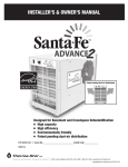
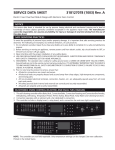
Issue 09/04
Santa Fe HC Dehumidifier
The Santa Fe HC dehumidifier performs multiple
functions in a compact enclosure, including
high-capacity dehumidification and air filtration.
True Performance
Off-the shelf, appliance grade dehumidifiers rate
their dehumidification capacities at 80°F, 60%
relative humidity (RH). The performance of these
devices drops significantly at cooler temperatures
typically found in basements and crawlspaces.
That means you may have to purchase multiple
off-the-shelf units to meet the performance of a
single Santa Fe HC.
• The Santa Fe HC is controlled by a dehumidistat
with positive “ON” and “OFF” settings with a
variable humidity setpoint range of “20%” to
“80%”. Humidity control is automatic and accurate.
• Low-temperature operation. The Santa Fe HC can continue
to remove humidity down to 55°F and will not freeze-up in
normal basement conditions.
• 115 VAC operation. A factory installed six foot power cord which plugs
into a standard 15 amp grounded outlet. The Santa Fe HC draws less
than 12 amps.
• Gravity water drain.
• The Santa Fe HC removes 135 pints of water per day, which is many
times the water removal of other dehumidifiers.
• Optional ductability promotes air distribution or allows remote location.
Figure 1: Santa Fe HC
P/N 4025081
Features and Benefits
Dehumidification
Integrated Filtration
Ducted or Free-Standing
Compact
The Santa Fe HC dehumidifier is designed to provide uncompromised indoor air
quality. The Santa Fe HC provides particulate filtration and humidity control in a single
compact free-standing or ducted (optional) enclosure. At the heart of the HC is a
high capacity, energy efficient dehumidifier capable of removing over 16.8 gallons
of water per day (at 80°F, 60% relative humidity) while using less than 13 amps of
electricity (120V). The unit maintains indoor humidity levels below 50%, the level
widely recognized as critical for controlling mold, mildew and dust mite populations.
Figure 2: Features and Benefits
© Copyright Therma-Stor LLC
Manual P/N 4025273
1
Table of Contents
Introduction
Features & Benefits
Precautions
1. Intended Application
2. Registration
3. Specifications
4. Installation
4.1 Location
4.1A In Humid Area, No Ducting
4.1B In Humid Area, Duct Inlet and/or Outlet
4.1C In Remote Area, Duct Inlet & Outlet
4.1D In Remote Area, Duct Outlet Only
4.1E In Remote Area, Duct Inlet Only
4.2 Remote Humidity Control
4.3 Electrical Requirements
4.4 Condensate (Water) Removal
4.5 Drainage and Trap
5. Ducting
5.1 Optional Ducting Kit
5.2 Ducting for Dehumidification
6. Operation
6.1 Humidity Control Adjustment
6.2 Blower (Fan) Switch
7. Maintenance
7.1 Air Filter
7.2 Blower Oiling
8. Service
8.1 Technical description
8.2 Troubleshooting
8.3 Defrost Thermostat
9. Service Parts List
10. Accessory/Replacement Parts List
11. Wiring Diagram
1
1
2
2
2
2
2
2
3
3
3
4
4
4
5
5
5
5
5
5
5
5
6
6
6
6
6
6
6
7
7
7
7
Read the installation, operation and maintenance instructions
carefully before installing and using this unit. Proper adherence
to these instructions is essential to obtain maximum benefit
from your Santa Fe HC dehumidifier.
READ AND SAVE THESE INSTRUCTIONS
1 Intended Application for Santa Fe HC
For the ideal installation, draw air from the central part of
the home and return it to isolated areas of the home like the
bedrooms, den, utility room, or family room. The ductwork
of the existing forced air system can be used to supply air
to the home.
2 Registrations
The Santa Fe HC conforms to UL STD 1995.
3 Specifications
Model:
Santa Fe HC (P/N 4025081)
Electrical:
110-120 VAC, 12 Amps, 60 Hz, grounded
Capacity:
135 pints/day @ 80°F, 60% RH
Operating Temp: 55°F min., 100°F max.
Air Flow:
355 CFM without external ducting
335 CFM @ .20 IWG external static
315 CFM @ .40 IWG external static
Refrigerant Charge:
1 lb., 12 oz. R22
Duct Connections:
Round 10" inlet, 10" outlet
Filter Size:
2" X 16" X 20"
Unit Size:
33"L x 21"W x 18.65"H
Shipping Size: 39”L x 25”W x 28.5”H
Unit Weight:
100 lb.
Shipping Weight: 138 lb.
4 Installation
4.1 Location
The Santa Fe HC can be installed in a variety of
locations to meet the owner's needs; other considerations
include:
1) Providing access to a 115 VAC power outlet
(7’ power cord is provided).
2) Locating near a floor or other suitable drain
(4’ drain hose included).
3) Do not install the Santa Fe HC with the exhaust of the
unit within 1’ of a wall or obstruction. Do not place the
unit near open water.
WARNING
The Santa Fe HC is designed to be installed indoors only.
1’ Minimum
Figure 3: Installation requires a
minimum 1’ exhaust clearance.
2
Santa Fe HC Owners Manual
4.1A in Humid Area, No Ducting (Fig. 4)
The simplest installation is to place the Santa Fe
HC in the humid area with no ducting. To ensure
optimal performance the air inlet and the outlet
of the unit must be at least 1' from walls and
other obstructions to air flow.
Inlet
Output
Figure 4: Installation in humid area with no ducting.
4.1B In The Humid Area, Duct Inlet
and/or Outlet (Fig. 5)
If the humid area is large or has high ceilings,
dehumidification can be improved by adding an
inlet and/or outlet duct to circulate and destratify
stagnant areas. For a large area, add inlet or
outlet ducting to create flow across the area's
greatest length.
Inlet
Output
For areas with ceilings higher than 12', use an inlet
duct to draw warm, moist air from near the ceiling.
See section 5 for attaching duct collars & ducting.
Figure 5: Installation in humid area with inlet and outlet ducting.
Inlet
Output
4.1C In A Remote Area, Duct
Inlet & Outlet (Fig. 6)
It is often desirable, especially in recreational rooms
and finished areas, to install the Santa Fe HC in an
adjacent equipment room or unfinished area. Air is
transferred between the humid room and the unit
via ducting. The factory mounted humidity control
on the Santa Fe HC cabinet may not sense the
humidity in the humid room accurately enough with
this installation method. If so, a remote humidity
control can be mounted in the humid room and
wired to the Santa Fe HC. Refer to the optional
equipment table in this document. Local electrical
codes must be followed when wiring the control.
Figure 6: Installation in a remote area with ducted inlet and outlet.
Santa Fe HC Owners Manual
3
4.1D In A Remote Area, Duct Outlet Only (Fig. 7)
A simplified remote installation method than above
uses ducting between the Santa Fe HC discharge
and the humid room; the Santa Fe HC inlet draws air
from the room in which it's located. This works well if
there is an adequate air flow path between the two
rooms; e.g. high door undercut, louvered door or wall
grill. This eliminates the need to remote mount the
humidity control.
Output
WARNING
Before installing the dehumidifier in the manner
described in section 4.1D (Fig. 7), call the factory
for specific instruction if backdraft devices (i.e.
hot water heaters) are present in the space to
be dehumidified.
4.1E In A Remote Area, Duct Inlet Only (Fig. 8)
When the Santa Fe HC is located in a room separate
from the main area to be dehumidified, it may be
desirable to dehumidify and/or slightly pressurize
that room. Pressurization assures that open combustion
devices do not back draft. This can be prevented by
installing a duct from the humid room to the Santa
Fe HC inlet and by allowing the Santa Fe HC to discharge dehumidified air into the room in which it's
located. An adequate air flow path must exist
between the two rooms for this method to work well.
Inlet
Figure 7: Installation in a remote area with ducted outlet only.
Inlet
A remote humidity control may need to be mounted
in the humid area and wired to the Santa Fe HC
to accurately maintain the desired humidity. Local
electrical codes must be followed when wiring the
control.
4.2 Remote Humidity Controls
All remote humidity controls should be mounted in a
central area of the the space to be dehumidified where it
can accurately sense the humidity of the air in the living
space and be accessed. All controls require field wiring
from the unit location to the panel mount location.
Figure 9:
Humidity/Fan
Control Panel
P/N 4024155
4.3 Electrical Requirements
The Santa Fe HC plugs into a common grounded outlet
on a 15 Amp circuit. It draws between 12 and 13 Amps
under normal operating conditions. If used in a wet area
(pool, spa room, or basement prone to flooding), a ground
fault interrupter protected circuit is recommended.
4
Output
Figure 8: Installation in a remote area with a ducted inlet only.
4.4 Condensate (Water) Removal
Condensate drains by gravity via the clear hose extending
from the unit. Use care to keep the hose as flat to the
floor as possible. Excessive humps or kinks will prevent
proper drainage. If the Santa Fe HC is located too far
from a floor drain for the attached hose to reach, 1/2"
PVC pipe can be used to extend it. It is commonly
available in 10' lengths from building supply, plumbing
and hardware stores. It will slide tightly inside the end
of the drain hose. Space and location requirements
should be taken into account when incorporating a
trap for the assembly as shown in Figure 12.
IMPORTANT
For proper drainage, the unit must be mounted so the
drain outlet is at least 4” above the floor drain, and
must be fully supported under the base.
Santa Fe HC Owners Manual
4.5 Drainage and Trap
The Santa Fe HC requires a trap. Unit should be located in an
area where the unit’s condensate (water) may be easily routed
to a suitable drain.
6 Operation
6.1 Humidity Control Adjustment
Figure 13: Humidity control dial.
Thread the PVC barb fitting into the drain outlet on the front
of the unit. Push the hose onto the barb fitting past two
barbs minimum to ensure a good fit.
Figure 10: PVC
barb fitting.
Figure 11: Drain outlet
Route the drain hose through the trap as shown in Figure 12.
Position the trap on the hose approximately 12” away from
the unit.
Figure 14: Humidity control label on unit.
The humidity control is an adjustable switch that closes when
the relative humidity of the air in which it is located rises to
the dial set point. It opens when the RH drops 4 to 6% below
the set point.
5 Ducting
Figure 12: Trap Diagram
Approximate Humidity Levels Per Setting
“Low”
35% to 45% Relative Humidity
“Normal” 45% to 55% Relative Humidity (Recommended)
“High”
55% to 65% Relative Humidity
5.1 Optional Ducting Kit
An inlet shroud with a 10" round collar and an 10" round
exhaust collar are available from the factory that will allow
round ducting to be attached to the inlet and/or outlet of
the Santa Fe HC. Refer to the optional equipment table
in this document.
The dehumidifier will run continuously until the relative
humidity (RH) is reduced to the humidity control dial setting.
The Santa Fe HC unit (and refrigerant based dehumidifiers in
general) will reduce a warm space's RH to a lower level than
that of a cool space. Therefore there is no benefit to set the
humidity control to excessively low levels in cool rooms. Doing
so will result in long periods of ineffective dehumidifier run time.
5.2 Ducting for Dehumidification
Ducting the Santa Fe HC requires consideration of the
following points:
Quality humidity meters are available from the factory and
are recommended to accurately monitor humidity levels.
Refer to the options and accessories table in this document.
Duct Sizing: For total duct lengths up to 50 feet, use a
minimum 8" diameter round or equivalent rectangular.
For longer lengths, use a minimum 10" diameter or
equivalent. Grills or diffusers on the duct ends must
not excessively restrict air flow.
Isolated Areas: Effective dehumidification may require
that ducting be branched to isolated, stagnant areas. Use
6" diameter branch ducting to each of two or three areas,
use 4" to each of four or more areas.
Santa Fe HC Owners Manual
5
6.2 Blower (Fan) Switch
Turning “ON” the fan switch will cause the unit's internal
blower to run continuously, whether the unit is dehumidifying
or not. This function is desirable if the unit is used for air
circulation.
the refrigerant pressure and temperature to drop. It next
enters the evaporator coil where it absorbs heat from the
incoming air and evaporates.
Turning “OFF” the fan switch will cause the unit’s internal
blower to run only while the unit is dehumidifying.
Figure 15: Blower
fan switch.
7 Maintenance
WARNING
NOTE: Do not operate the unit without the filter or with
a less effective filter. The heat exchange coils inside
the unit could become clogged and require disassembly
to clean.
7.1 Air Filter
The Santa Fe HC ships with a pleated fabric filter standard.
This should be checked monthly. Operating the unit with a
dirty filter will reduce dehumidifier capacity and efficiency
and may cause the compressor to cycle on and off unnecessarily.
The pleated fabric filter can generally be vacuumed clean
several times before needing replacement. Replacement
filters can be ordered from the factory. To order a replacement
filter, refer to the options and accessories table in this document.
7.2 Blower Oiling
The blower motor has been lubricated at the factory for many
years of normal operation.
8 Service
IMPORTANT
WARNING: Servicing the Santa Fe HC with its high
pressure refrigerant system and high voltage circuitry
presents a health hazard which could result in death,
serious bodily injury, and/or property damage. Only
qualified service people should service this unit.
8.1 Technical Description
The Santa Fe HC uses a refrigeration system similar
to an air conditioner's to remove heat and moisture from
incoming air, and add heat to the air that is discharged.
Hot, high pressure refrigerant gas is routed from the
compressor to the condenser coil. The refrigerant is cooled
and condensed by giving up its heat to the air that is about
to be discharged from the unit. The refrigerant liquid then
passes through a filter/drier and capillary tubing which cause
6
Figure 16: Santa Fe HC refrigeration system.
The evaporator operates in a flooded condition, which means
that all the evaporator tubes contain liquid refrigerant during
normal operation. A flooded evaporator should maintain
constant pressure and temperature across the entire coil,
from inlet to outlet. The mixture of gas and liquid refrigerant
enter the accumulator after leaving the evaporator coil. The
accumulator prevents any liquid refrigerant from reaching the
compressor. The compressor evacuates the cool refrigerant
gas from the accumulator and compresses it to a high
pressure and temperature gas to repeat the process.
8.2 Troubleshooting
No dehumidification, neither blower nor compressor run with
fan switch OFF.
1. Unit unplugged or no power to outlet.
2. Humidity control set too high or defective.
3. Loose connection in internal wiring.
No dehumidification, compressor does not run but blower
runs with fan switch OFF and humidity control turned to ON.
1. Defective compressor or compressor run capacitor.
2. Loose connection in compressor circuit.
3. Defective compressor overload.
4. Defrost thermostat open.
Blower runs with fan switch OFF, but compressor cycles on & off.
1. Low ambient temperature and/or humidity causing unit to
cycle through defrost mode.
2. Defective compressor overload.
3. Defective compressor.
4. Defrost thermostat defective.
Blower does not run with fan switch in either position.
Compressor runs briefly but cycles on & off.
1. Loose connection in blower circuit.
2. Obstruction prevents impeller rotation.
3. Defective blower.
4. Defective blower switch.
Santa Fe HC Owners Manual
Evaporator coil frosted continuously, low
dehumidifying capacity.
1. Defrost thermostat loose or defective.
2. Low refrigerant charge
3. Dirty air filter or air flow restricted.
11 Wiring Diagram
8.3 Defrost Thermostat
The defrost thermostat is attached to the refrigerant suction
tube between the accumulator and compressor. It will
automatically shut the compressor off if the low side
refrigerant temperature drops due to excessive frost
formation on the evaporator coil. The blower will continue
to run, causing air to flow through the evaporator coil and
melt the ice. When the ice has melted, the evaporator
temperature will rise and the thermostat will restart the
compressor.
9 Service Parts List
PART NO.
4021395
4021396
4021470
4021589
4025087
4021469
4025075
4025076
4025224
4025244
4025298
4020554
DESCRIPTION
Coil, Evaporator
Coil, Condenser
Thermostat, Defrost Control
Tube, CU, CPLRY
Filter, Drier
Controller, Humidity, Face Mount
Compressor
Fan, Motorized Impeller
Capacitor, Impeller
Capacitor, Run
Overload, Compressor
Switch, Rocker, On-Off
Figure 17: Santa Fe HC Wiring Diagram
Figure 18: Stand (P/N 4025463)
10 Accessory/Replacement Parts
4021475
4021626
4025264
4021495
4025463
4025466
Filter, Air
Hose, Vinyl
Trap, Drain
Knob, Plastic, Black
Stand
Duct Collar Kit
To order, contact your reseller or
call 1-800-533-7533.
Santa Fe HC Owners Manual
Figure 19: Duct Collar Kit (P/N 4025466)
7
Santa Fe HC Dehumidifier Limited Warranty
WARRANTOR:
Therma-Stor LLC
PO Box 8050
Madison, WI 53708
and does not cover any defect, malfunction, etc.
resulting from misuse, abuse, lack of normal care,
corrosion, freezing, tampering, modification,
unauthorized or improper repair or installation,
accident, acts of nature or any other cause
beyond Therma-Stor LLCs reasonable control.
Telephone: 1-800-533-7533
WHO IS COVERED: This warranty extends only
to the original residential end-user of the SANTA
FE HC dehumidifier, and may not be assigned
or transferred.
FIRST YEAR WARRANTY: Therma-Stor LLC
warrants that, for one (1) year the SANTA FE HC
dehumidifier will operate free from any defects
in materials and workmanship, or Therma-Stor
LLC will, at its option, repair or replace the
defective part(s), free of any charge.
SECOND THROUGH FIFTH YEAR WARRANTY:
Therma-Stor Products further warrants that for a
period of five (5) years, the condenser, evaporator,
and compressor of the SANTA FE HC dehumidifier
will operate free of any defects in material or
workmanship, or Therma-Stor LLC, at its option,
will repair or replace the defective part(s),
provided that all labor and transportation charges
for the part(s) shall be borne by the end-user.
END-USER RESPONSIBILITIES: Warranty service
must be performed by a Servicer authorized
by Therma-Stor LLC. If the End-user is unable
to locate or obtain warranty service from an
authorized Servicer, he should call Therma-Stor
LLC at the above number and ask for the
Therma-Stor LLC Service Department., which
will then arrange for covered warranty service.
Warranty service will be performed during normal
working hours.
The End-user must present proof of purchase
(lease) upon request, by use of the warranty
card or other reasonable and reliable means.
The end-user is responsible for normal care. This
warranty only applies to residential applications,
8
LIMITATIONS AND EXCLUSIONS: If any SANTA FE
HC Dehumidifier part is repaired or replaced, the
new part shall be warranted for only the remainder
of the original warranty period applicable thereto
(but all warranty periods will be extended by the
period of time, if any, that the SANTA FE HC
Dehumidifier is out of service while awaiting
covered warranty service).
UPON THE EXPIRATION OF THE WRITTEN
WARRANTY APPLICABLE TO THE SANTA FE HC
DEHUMIDIFIER OR ANY PART THEREOF, ALL
OTHER WARRANTIES IMPLIED BY LAW, INCLUDING
MERCHANTABILITY AND FITNESS FOR A
PARTICULAR PURPOSE, SHALL ALSO EXPIRE.
ALL WARRANTIES MADE BY THERMA-STOR LLC
ARE SET FORTH HEREIN, AND NO CLAIM MAY
BE MADE AGAINST THERMA-STOR PRODUCTS
BASED ON ANY ORAL WARRANTY. IN NO EVENT
SHALL THERMA-STOR PRODUCTS, IN CONNECTION
WITH THE SALE, INSTALLATION, USE, REPAIR OR
REPLACEMENT OF ANY SANTA FE HC DEHUMIDIFIER
OR PART THEREOF BE LIABLE UNDER ANY LEGAL
THEORY FOR ANY SPECIAL, INDIRECT OR
CONSEQUENTIAL DAMAGES INCLUDING WITHOUT
LIMITATION WATER DAMAGE ( THE END-USER
SHOULD TAKE PRECAUTIONS AGAINST SAME),
LOST PROFITS, DELAY, OR LOSS OF USE OR
DAMAGE TO ANY REAL OR PERSONAL PROPERTY.
Some states do not allow limitations on how
long an implied warranty lasts, and some do
not allow the exclusion or limitation of incidental
or consequential damages, so one or both of
these limitation may not apply to you.
LEGAL RIGHTS: This warranty gives you specific
legal rights, and you may also have other rights
which vary from state to state.
Santa Fe HC Owners Manual
Santa Fe HC Owners Manual
9
PO Box 8050
1919 S. Stoughton Road
Madison, WI 53708
Phone: 608-222-5301
Fax: 608-222-1447
Web: www.thermastor.com
Email: [email protected]
10
Information in this document is subject to change without notice.
No part of this document may be reproduced or transmitted in any
form or by any means, electronic or mechanical, for any purpose,
without the express written permission of Therma-Stor LLC.
© 2004 Therma-Stor LLC. All rights reserved.
Santa Fe HC Owners Manual