1
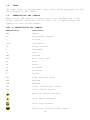
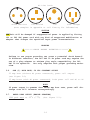
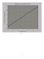
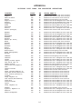
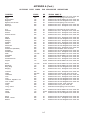
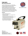
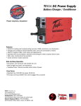
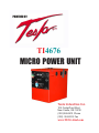
'%()$)-&./ TI4676 !"#$%&'%()$&*+", Tesla Industries Inc. 109 CenterPoint Blvd. New Castle, DE 19720 (302)324-8910 Phone (302) 324-8912 Fax www.TESLAind.com WARNING *******SHOCK HAZARD POTENTIAL******* IMPROPER USE/FAILURE TO FOLLOW INSTRUCTIONS IN OPERATORS MANUAL CAN RESULT IN UNIT FAILURE AND/OR POSSIBLE INJURY, OR DEATH, BY ELECTRICAL SHOCK. THE TI4676 IS A MAINTENANCE FREE, SEALED UNIT NO REPAIRS ARE AUTHORIZED. WARRANTY WILL BE VOID IF UNIT IS TAMPERED WITH. FOR TECHNICAL SUPPORT CONTACT: TESLA INDUSTRIES INC. 109 CENTERPOINT BLVD. CENTERPOINT INDUSTRIAL PARK NEW CASTLE,DELAWARE 19720 PH.(302)324-8910 FAX (302)324-8912 www.teslaind.com WARNING *******SHOCK HAZARD POTENTIAL******* ATTEMPTS TO OPEN OR ENTER THE INSIDE OF THIS UNIT (BY USING ANY TOOL OR DEVICE; i.e. PROBE, BORESCOPE, etc.) CAN RESULT IN UNIT FAILURE AND/OR POSSIBLE INJURY BY ELECTRICAL SHOCK. THIS UNIT IS MAINTENANCE FREE AND SHALL NOT BE OPENED OR DISASSEMBLED FOR ANY REASON. ***SHIPPING HAZARDS*** NONE “DRY” Non-spillable, POWER CELL (battery), No Free liquids, to leak or toxic gases. Always protect unit from short circuit. Return Power cells to Tesla for Recycling. i TABLE OF CONTENTS TITLE Page CHAPTER 1 INTRODUCTION 1-1 CHAPTER 2 UNIT DESCRIPTION AND OPERATION 2-1 Section I Unit 2-1 Section II Description 2-2 CHAPTER 3 OPERATING LIMITS AND RESTRICTIONS 3-1 Section I General 3-1 Section II Operational Restrictions and Safety Limits 3-1 CHAPTER 4 OPERATING AND INSTALLATION PROCEDURES 4-1 Section I Installation Procedures 4-1 Section II Unit Operation 4-1 Section III Operating Procedures 4-2 Section IV Functional Check Procedures 4-5 CHAPTER 5 PERFORMANCE DATA 5-1 Section I Introduction 5-1 Section II Data Criteria 5-2 CHAPTER 6 CARE AND MAINTENANCE 6-1 Section I Unit Care 6-1 Section II Maintenance 6-2 CHAPTER 7 Push to Test Operation 7-1 INDEX Index 1 LIST OF ILLUSTRATIONS Figure Title Page 2-1 Dimensions 2-3 2-2 Fuse Setting Procedures 2-4 5-1 Temperature Conversion Chart 5-3 5-2 Discharge Load Curve 5-4 5-3 Maximum Output Current 5-5 ii CHAPTER 1 INTRODUCTION 1-1. GENERAL These instructions are for use by the owner/operator. They apply to handling and operation of the TI4676 Micro Power Unit (MPU). 1-2. WARNING, CAUTION, AND NOTE DEFINED A warning, caution, or note is used to emphasize important and critical instructions as defined for the following conditions: WARNING An operating procedure, practice, etc., which, if not correctly followed, could result in personal injury or loss of life. CAUTION An operating procedure, practice, etc., which,if not strictly observed, could result in damage to or destruction of equipment. NOTE An operating procedure, condition, etc., which is essential to highlight. 1-3. DESCRIPTION This manual contains the complete operating instructions and procedures for the TI4676 MPU. The TI4676 is intended to provide an on-board battery along with DC electrical ground power for aircraft systems and maintenance ground support operations. The unit is designed to provide 24 volt DC electrical power output for aircraft engine starting and 24 or 28.5 volts DC electrical support for ground maintenance, avionics/ electrical trouble shooting and testing. The unit also has a built in capacity tester (push to test button), and recharge rate indicator. The TI4676 MPU has a internal, independent, intelligent recharger that will enable the MPU to be rapidly recharged from either the aircraft generator or any 120-240 50/60 Hz VAC common power source. The observance of procedures, limitations and performance criteria is essential to ensure peak operating efficiency and to maximize operational capabilities and life of the TI4676 MPU. 1-1 1-4. INDEX The index lists, in alphabetical order, every titled paragraph and figure contained in this manual. 1-5. ABBREVIATIONS AND SYMBOLS Abbreviations and symbols are used within text, headings and titles. Unless otherwise indicated, the following list of abbreviations and symbols are used in this manual: LIST OF ABBREVIATIONS AND SYMBOLS Abbreviation Definition Amp Ampere AC Alternating Current C Celsius cont Continuous DC Direct Current F Fahrenheit Ft Feet FWD Forward MPU Micro Power Unit Hr Hour Hz Hertz Kg Kilograms KW Kilowatts ° Degree LED Light Emitting Diode MAX Maximum MIN Minimum VAC Volts, Alternating Current VDC Volts, Direct Current Explosion Hazard Potential Shock Hazard Potential Guard from moisture ᮂ ᮐ᭼ᮍ ᭛ ᮁ ᮍᮊ ᮈ ᭛ ᮄ ᮉ ᭾ᮊᮍ ᮍᮀ ᭾ᮏ ᮋ ᮊᮒᮀ ᮍ᭛ ᮎ ᮊᮐ ᮍ᭾ᮀ Guard from incorrect power source 1-2 1-6. FORMS AND RECORDS NONE REQUIRED. 1-7. USE OF WORDS SHALL, SHOULD, AND MAY. Within this technical manual the word “shall” is used to indicate a mandatory requirement for proper operation and warranty purposes. The word “should” is used to indicate a non-mandatory but preferred method of accomplishment. The word “may” is used to indicate an acceptable method of accomplishment. 1-3 CHAPTER 2 UNIT DESCRIPTION AND OPERATION SECTION I. UNIT 2-1. GENERAL The TI4676 (Figure 2-1) is a compact, portable and highly versatile 24/ 28.5 VDC electrical MPU. The unit incorporates a 120-240 50/60 Hz to 28.5 VDC converter, a 24 volt unique (dry) power cell and an internal intelligent 120-240 50/60 Hz VAC charger to recharge the power cells. In addition the MPU incorporates a push to test button which gives the user the ability to test the capacity of the power cells These builtin features give the TI4676 self-sufficiency in an aircraft battery, and long term ground operations with AC electrical power. Aircraft battery operations rely on the unique dry-cell batteries that can be rapidly recharged from the aircraft generator or any common 120-240 50/60 Hz VAC source. Ground operations incorporate the continuous 12 Amp output of the 120-240 50/60 Hz VAC to 28.5 VDC converter, or a combination of converter and power cell output to provide 24 VDC output. The following are the unit’s five (5) main operational support capabilities: a. 24 VDC 1500 amp peak power output for engine starting or constant (one hour) rated power output (without a 120-240 50/60 Hz VAC power source) for short-term trouble shooting. b. 24 VDC constant (one hour) rated power output or variable high load demand output (less than one hour) with a 120-240 50/60 Hz VAC power source for extended maintenance (hangar) and routine flight line maintenance, ground support power. c. 28.5 VDC continuous rated (AC to DC converter) power output with a 120-240 50/60 Hz VAC power source for hangar and routine flight line maintenance support. d. Rapid recharge of the unit’s power cells from aircraft generator or any 120-240 50/60 Hz VAC common power source. This feature eliminates the need for special recharge equipment and dedicated maintenance support man-hours. e. Built in Capacity tester and state of recharge indicator. 2-1 WARNING Check fuse holder window to ensure the fuse setting reads either 120 or 240 prior to connecting recharge cord to AC power source. Fuse setting (120/240) must match AC power source (hangar wall, flight line AC power) prior to connecting MPU for recharging. Ὢ ὸὤή ὧὃ Ὡ ήὲὰ ὃ Ὤ ά ὦὲή ήὨ ὦί έ ὲὺὨ ήὃ ὶ ὲὸ ήὦὨ 120 VAC Setting 240 VAC Setting (SEE PAGE 2-4 FOR DETAILS ON FUSE SETTING PROCEDURES) SECTION II DESCRIPTION 2.2. GENERAL SPECIFICATIONS WEIGHT UNIT: 48.2 lbs. (21.8 Kg) AC POWER CORD: 0.4 lbs. (0.18 Kg) INPUT POWER AC TI4676: 110-240 VAC 50/60 Hz 6.50 amps max. OUTPUT POWER DC CONVERTER: 28.5 VDC TO 12 AMPS, 24 VDC 15 AMPS AND ABOVE. POWER CELLS: 24 VDC 23 AMP Hour PEAK OUTPUT: 1500 AMPS POWER CELL DRY, HIGH RATE DISCHARGE, RECHARGEABLE, MAINTENANCE-FREE OPTIONAL ACCESORIES SHIPPING CASES Used for shipping and storage. Part # TI7000-023 2-2 !"#$%&' !"# Fuse Setting Procedures for Switching Voltages or Changing Blown Fuses 1) Grab both tabs on left and right side of the fuse clip. Press tabs inward and pull fuse clip out of housing GENTLY. 2) Completely pull fuse clip from housing, being careful not to drop the fuses from the fuse clip. 3) Note: The fuses are not fastened into the fuse clip, they are lose. Take care to ensure fuses are not dropped or lost. 4) GENTLY pull the white clip from the fuse clip, taking care not to bend any of the tabs. (See enlargement 1) TABS ENLARGEMENT 2 120 VAC SETTING ENLARGEMENT 1 7) Replace the white clip back into the fuse clip. Take care not to damage the tabs. ENLARGEMENT 3 240 VAC SETTING 5) Completely remove the white clip from the fuse clip. 6) Ensure that the proper voltage is selected on the white clip. (See Enlargement 2 & 3) 8) Completely insert white clip in to fuse clip (GENTLY) until it snaps into place. 9) Insert fuse clip back into fuse housing EVENLY on both sides. DO NOT FORCE, if fuse clip does not go in easy, it means fuses are misaligned, realign fuses and insert again. 2-4 10) Snap fuse clip back into the housing (GENTLY). DOUBLE CHECK VOLTAGE WINDOW PRIOR TO PLUGGING UNIT INTO AC POWER CHAPTER 3 OPERATING LIMITS AND RESTRICTIONS SECTION I. GENERAL 3-1. PURPOSE Chapter 3 includes all important operating limits and restrictions that must be observed for proper and safe operation of the TI4676 micro power unit. 3-2. GENERAL The operating limitations set forth in this chapter are the direct result of design analysis, testing, and operating experience. Compliance with these limitations and restrictions will ensure that owners/operators obtain maximum continued capability from the TI4676 ground power unit. SECTION II. OPERATIONAL RESTRICTIONS AND SAFETY LIMITS 3-3. POWER CELL RECHARGE LIMITS Any time the unit’s power cells are fully discharged the unit shall be recharged within 24 hours to prevent performance degradation and ensure maximum life. CAUTION Unit’s power cells may be damaged if recharged by NiCad or Lead Acidtype battery chargers. Power cells should only be charged by either the TI4676 MPU internal charger and the AC power cord furnished with the equipment, or off the aircraft generator when installed on the aircraft. 3-1 3-4. 120-240 50/60 Hz VAC CHARGER AND AC TO DC CONVERTER LIMITS The unit is designed with a single point AC receptacle for external power to operate both the internal charger and converter. The unit’s AC voltage range can be factory set from 105 to 250 VAC at 50 to 60 Hz depending upon customer requirements. The AC power cord provided with the unit is the mechanism that ensures the specified AC power source is properly supplied to the unit (see paragraph 3-5). Use no others. INTERNAL CHARGER: NO LIMIT AC power cord can remain connected when power cells are fully charged. When the power cells are fully charged the unit’s intelligent charger will go to a stand-by mode, LED will stay green or flicker, monitor the power cells state of charge and only charge the power cells to ensure they stay at maximum capacity. INTERNAL AC TO DC CONVERTER: LIMITED (see paragraph 3-6, 3-8 and 310). AC power cord does not have to be disconnected when converter power output is no longer required. Once DC power demand is terminated the unit’s intelligent charger will remain on line to ensure power cells are charged to maximum capacity. CAUTION * 8 $ 5 ’ ) 5 2 0 ,1 & 2 5 5 ( & 7 32: (5 628 5&( Unit will be damaged if unapproved AC power is applied. 3-5 AC POWER CORD LIMITS The AC power cord governs which AC power source the unit is set to operate from. The TI4676 is supplied with a single customer specified AC power cord. Some customers may specify a non North American AC option (for worldwide mobility see appendix A). Each power cord is marked accordingly. FOR MORE INFORMATION ON POWER CORDS SEE APPENDIX A 3-2 AC Line Cords North American Old British U.K Cont. Europe (more examples in appendix or call factory for information) CAUTION Unit will be damaged if unapproved AC power is applied by fitting 120 or 240 VAC power cord with any kind of unapproved modification or adapter that changes the specified input power characteristics. * 8 $ 5 ’ ) 5 2 0 ,1 & 2 5 5 ( & 7 32: (5 628 5&( WARNING ********SHOCK HAZARD POTENTIAL********* Failure to use proper grounding can cause a potential shock hazard! In different countries, the 240 VAC 50 Hz power cord may require the use of a plug adapter to achieve plug style compatibility for 240 VAC 50 Hz operation. Use only adapters with proper grounding mechanism. 3-6. ONE (1) HOUR RATE, 24 VDC CONSTANT OUTPUT 23 amp hour (without AC power connected), power cell output. (see Figure 5-2) 35 amp hours (with AC power connected), both power cell and AC to DC converter output. NOTE If power output is greater than rated amp hour rate, power cell discharge rate will increase correspondingly. 3-7. RATED PEAK OUTPUT (ENGINE STARTING) 1500 peak amps at 25oC (77oF) (See Figure 5-3). 3-3 3-8. CONTINUOUS OUTPUT RATE, 28.5 VDC CONSTANT OUTPUT 35 Amps at 1 hour (with AC power connected) NOTE If current demand exceeds 12 amps, converter output voltage will drop below 28.5 VDC and two or more LED status indicator bars will illuminate. If all LED status indicator bars illuminate, both the converter and power cells are supplying 24 VDC power output (see paragraph 3-4 and 4-7) 3-9. ENGINE STARTING POWER Operators should always ensure the unit is charged above 80% prior to ground support engine starting. However, circumstances may exist during use where unit recharge is not readily available and immediate external engine starting power is required. The following provides minimum states of charge necessary to provide ample power for an efficient engine start under specific current load demands. ENGINE START CURRENT LOAD DEMAND MINIMUM CHARGE Under 650 peak starting amps 40% charged 650 - 850 peak starting amps 50% charged 850 - 1000 peak starting amps 60% charged 1000 - 1200 peak starting amps 70% charged 1200 - 1500 peak starting amps 80% charged 3-10. TEMPERATURE Temperatures refer to the unit’s cold/heat soaked temperature. The ambient temperature that a unit is exposed to for one (1) hour or more shall establish a unit’s cold/heat soaked temperature. If unit’s cold/ heat soaked temperature exceeds operating temperature range, unit shall be stabilized prior to operation as follows: COLD SOAKED, warmed for a minimum of 3 hours above +10Co (+41oF) or 2 hours above +20Co (+68oF); WARMED SOAKED, cooled for 1 hour below +38Co (+100oF). Operating range: without AC power -40Co (-40oF) TO +60Co (+140oF) with AC Power -30Co (-22oF) TO +50Co (+124oF) Storage range: 60Co (-76oF) TO +60Co (+140oF) (C0NTINUED ON NEXT PAGE) 3-4 CAUTION Unit may be damaged if operated when unit’s cold or heat soaked temperature exceed the specified limit. If unit is operated when cold or heat soaked temperature limit is exceeded; a full functional check should be accomplished prior to continued use. NOTE If unit should overheat, an over-temperature sensor will shut down 120240 50/60 Hz AC functions (charger and converter) until unit cools to normal operating temperatures. 3-11. ENVIRONMENTAL Operating any electrical equipment in the presence of moisture creates possible safety hazards and/or potential for equipment damage. Every effort has been made, within the scope of existing technology to prevent foreseeable safety hazards and make the TI4676 moisture resistant to prevent damage or failure. If the TI4676 is exposed to moisture, preventive measures and precautions shall be taken to: a. Prevent accumulation of moisture on AC and DC connectors/receptacles b. Minimize moisture entering FWD inlet and AFT outlet cooling fan vent ports The limits and operational constraints listed below shall apply for the following environmental (weather) conditions during recharging process: Heavy or steady rain: OPERATION NOT RECOMMENDED DURING RECHARGING PROCESS Light rain, drizzle: NO CONVERTER OR CHARGER 120-240 50/60 Hz VAC Fog, snow or sleet: POWER SHALL BE APPLIED. Unit inlet and outlet vent ports shall be covered from exposure. shall be kept horizontal. 3-5 Unit WARNING ********SHOCK HAZARD POTENTIAL********* Severe injury, or Death, from electrical shock is possible when personnel and/or TI4676 are wet during use and when 120-240 50/60 Hz VAC power is being supplied to unit. CAUTION Damage may occur if unit is operated after exposure to moisture (rain, drizzle, fog, sleet or snow) or moisture contamination is suspected. DO NOT USE until unit’s exterior and receptacles are dried. Operation shall be restricted to use without 120 or 240 power cord. DO NOT CONNECT 120 or 240 VAC power cord until unit has been dried for a MINIMUM of one (1) hour, prior to use. Blowing sand or dust: when 120-240 50/60 Hz zontal during use. Minimize exposure to sand and dust AC power is used. Unit shall be kept hori- 3-6 CAUTION Unit damage may occur if inlet and outlet vent ports are obstructed and/or cooling airflow is restricted. Back Vent 3-13. Side Vents Cooling Fan UNIT OPERATION DURING AIRCRAFT FUELING/DEFUELING Power output is restricted to 24 VDC power cell output only. DO NOT CONNECT 120 or 240 VAC POWER SUPPLY. 120-240 50/60 Hz VAC power (charger or AC-DC converter) functions of unit shall not be operated during any aircraft fuel handling operation. WARNING *******FIRE/EXPLOSION HAZARD POTENTIAL******** Severe injury, or Death, may occur from fire or explosion, as a result of electrical sparks produced near fuel vapors. 3-7 CHAPTER 4 OPERATING AND INSTALLATION PROCEDURES SECTION I. UNIT INSTALLATION 4-1. INSTALLATION 1. Remove original aircraft battery and dispose of properly (follow your aircraft’s manual for proper removal and disposal of aircraft battery). 2. Ensure that the TI4676 MPU is fully charged. Remove AC cord and place the TI4676 MPU in the same position of the original battery (ensure that the DC receptacle is oriented in the same position as the original battery). 3. Position the TI4676 MPU so that the aircraft battery tie-down bolts are aligned with the bracket on the MPU. Secure the aircraft tie-down bolts so that the MPU is securely fastened. 4. Attach the aircraft DC plug so that it is fully seated into the MPU receptacle. 5. Because the TI4676 MPU uses monolithic dry-cell batteries, there is no need to attach the ventilation tubes to the MPU. 6. Because there is no hazardous materials or liquids in the cells, there is no risk of thermal runaway, and therefore no need to hook up temperature sensors. SECTION II. OPERATING PROCEDURES 4-2. GENERAL Correct operation of the TI4676 includes both pre-use and operational checks of the unit. Knowledge of the operating limits, restrictions, performance, unit capabilities and functions is fundamental to correct and safe operation. The operator shall ensure compliance with the instructions in this manual that affect operational safety and the warranty of the unit. 4-3. OPERATING LIMITS AND RESTRICTIONS The minimum, maximum and normal operating ranges result from careful engineering and evaluation of test data. These limitations must be adhered to during all phases of operation. Refer to Chapter 3, Section II, OPERATING LIMITS AND RESTRICTIONS, for detailed information. 4-4. PERFORMANCE Refer to Chapter 5, PERFORMANCE DATA to determine the capability of the TI4676. Consideration must be given to changes in performance resulting from variations in ambient temperature, mode of operation, state of charge (with or without 120 or 240 VAC power), and aircraft DC bus system inefficiency (voltage drops). 4-1 SECTION II. OPERATING PROCEDURES (cont.) 4-5. OPERATING PROCEDURES This section deals with normal procedures, and includes all steps necessary to ensure safe and efficient operation of the TI4676. As experience is gained with the TI4676, the user will be able to maximize the unit’s unique capabilities to enhance the flexibility of aircraft maintenance and support operations. NOTE When the TI4676 is not in use, it should always remain plugged into a suitable AC power source to insure operational readiness at all times. REMEMBER, when the AC line cord is plugged in, the unit must be placed in a position to allow the cooling fan to operate unobstructed! 4-6. BEFORE OPERATION CHECK 1. CHECK FUSE WINDOW FOR PROPER SETTING (120/240) BEFORE PLUGGING UNIT INTO THE AC POWER SOURCE TO BE USED. NOTE: Under a full charge the LED indicator should show a single steady green bar or the entire LED will be flickering. The fan will also exhibit ratcheting but will not come on. This is normal operation and the unit will go into standby mode, the unit is ready for use. Capacity % 100 90 80 70 60 50 40 30 <20 2. CHECK UNIT FOR EVIDENCE OF DAMAGE - Check for dents, punctures, case distortion or misalignment, cracked or loose connectors, and that cooling fan is functioning ( cooling fan can be checked by pressing push to test button ). 4-2 CAUTION REMEMBER, when the AC line cord is plugged in, the unit must be placed in a position to allow the cooling fan to operate properly! Unit may overheat if cooling fan fails. Do not operate if cooling fan fails. (More than one green bar is present on bar graph) Make certian there is at least 2-3 inches clearence on the vent fan of the MPU when connected to AC, to provide sufficent ventillation. 3. CHECK AIRCRAFT PLUG AND MPU CONNECTORS FOR DAMAGE - Check cable for cuts, chafing or evidence of being crushed. Check connectors for cracks, cuts, distortions, excessive wear, broken/loose fasteners or loose cable attachment. 4-7 POWER CELL RECHARGE 1. CONNECT AC POWER CORD TO UNIT (CHECK FUSE WINDOW FOR PROPER SETTING). - Ensure 120 or 240 VAC power cord is properly connected to an approved AC power supply. Unit shall be in an upright position according to aircraft specifacations to ensure unit’s vent ports are free from blockage. After approximately 5-8 seconds, ensure unit’s LED status indicator illuminates indicating power cell state of charge and cooling fan is operating. 4-3 CAUTION Unit may overheat if cooling fan fails. Do not operate if cooling fan fails. 2. CHECK FOR FULL CHARGE INDICATION - After 1 HR 15 minutes, LED charge indicator should show a single steady or flickering LED bar when fully charged. AC power may be left connected to unit when power cells are fully charged. NOTE: Under a full charge the LED indicator should show a single steady green bar or the entire LED will be flickering. The fan will also exhibit ratcheting but will not come on. This is normal operation and the unit will go into standby mode, the unit is ready for use. 4-4 SECTION III. FUNCTIONAL CHECK PROCEDURES AND TROUBLE SHOOTING 4-8. FUNCTIONAL CHECK PROCEDURES This section deals with normal functional check procedures, and includes all steps necessary to ensure the TI4676 is functioning within specific operational parameters prior to operational use. As users gain experience with the TI4676, they will incorporate these functional checks as a routine practice. 4-9. REQUIRED EQUIPMENT FOR FUNCTIONAL CHECK. FLUKE OR EQUIVALENT TYPE DIGITAL MULTIMETER. 4-10. DC FUNCTIONAL CHECK. 1. CHECK UNIT FOR EVIDENCE OF DAMAGE - Check for dents, punctures, case distortion or misalignment, cracked or loose connectors. If no damage is evident proceed to step two. IF DAMAGE IS EVIDENT contact distributor or manufacturer. 2. ENSURE UNIT IS NOT PLUGGED INTO 120 OR 240 VDC. Unplug AC power if plugged in. 3. CHECK UNIT INTERNAL RESISTANCE (TEST FOR SHORTS) - Better than 10 Mega-ohms. Ensure no short exists. Negative (-) DC receptacle terminal and unit case. Positive (+) DC receptacle terminal and unit case. 4. CHECK DC VOLTAGE READING AT DC RECEPTACLE TERMINALS. 24 to 25.5 VDC depending on state of charge. 5. PLUG IN 120 OR 240 POWER CORD.(CHECK FUSE WINDOW FOR PROPER SETTING). - Ensure power unit is connected to a suitable AC power source (120 USA or 240 European). 6. CHECK UNIT FOR STATE OF CHARGE - Unit shall be in a position to ensure unit’s vent ports are free from blockage. After approximately 5-8 seconds, unit LED status indicator shall illuminate indicating power cell state of charge. Ensure LED status indicator and cooling fan is operational. Prior to continuing to step 7, the LED status indicator should show a single green bar (last LED bar) or a flickering LED status bar to indicate the unit’s power cells are fully charged. Also under full charge the fan will ratchet but not enable. NOTE: Under a full charge the LED indicator should show a single steady green bar or the entire LED will be flickering. The fan will also exhibit ratcheting but will not come on. This is normal operation and the unit will go into standby mode, the unit is ready for use. 4-5 7. CHECK DC VOLTAGE READING AT DC RECEPTACLE TERMINALS. cells are fully charged (see step 6.) Ensure power 28.5 (±0.57 VDC) with power cells at full state of charge. 8. FUNCTIONAL CHECK COMPLETE - Unit should remain plugged in to AC power until ready for installtion in aircraft. 4-6 CHAPTER 5 PERFORMANCE DATA SECTION 1. INTRODUCTION 5-1. PURPOSE This chapter provides performance data for the TI4676. Continual reference to this information will enable the user to obtain maximum performance, utilization and service life from the TI4676. Although maximum performance is not always required, regular referral to this chapter is recommended for the following reasons: a. To generate knowledge of unit’s performance margins to enable the operator to make sound judgment when unexpected conditions or alternate operational requirements are encountered. b. To enable the user to readily recognize situations requiring maximum performance. c. To gain experience in accurately estimating the effects of variables for which data is not presented. d. To help the operator determine if an aircraft system malfunction exists by comparing actual performance with expected performance. NOTE The information provided in this chapter is primarily intended for operational planning and is most useful when planning operations under unfamiliar conditions or environmental extremes. The data may also be used to establish local operating procedures and to ensure unit’s operational life is maximized. 5-2. GENERAL The data presented covers the maximum range of conditions and performance that can reasonably be expected. In each area of performance, the effects of temperature and DC electrical load demand relating to the ground power support requirements are presented. Wherever practical, data is presented conservatively. However, NO GENERAL CONSERVATISM HAS BEEN APPLIED. All performance data presented is within the applicable limits of the TI4676 MPU. 5-1 SECTION II DATA CRITERIA 5-3 DATA BASIS The type of data used is indicated at the bottom of each performance chart under DATA BASIS. The applicable report and date of the data are also given. The data provided generally are based on one of three categories: a. Derived From Actual Controlled Testing. obtained on a similar unit type. Controlled test data b. Calculated Data. Data based on tests, but not on a similar unit type placed under a controlled test. c. Estimated Data. Data based on estimates using rules of physics, mathematics, and electrical engineering principles and concepts, but not verified by tests. 5-4. SPECIFIC CONDITIONS The data presented are accurate only for specific conditions listed under the title of each chart or graph. Variables for which data are not presented, but which may affect that phase of performance, are discussed in associated text. Where data is available or reasonable estimates can be made the amount that each variable affect performance will be given. 5-5. GENERAL CONDITIONS In addition to the specific conditions, the following general conditions are applicable to the performance data. a. Variation in Aircraft. Power demand differences between individual aircraft of the same make and model are known to exist due to variations in DC electrical system efficiency. These differences, however, are considered insignificant and are not individually accounted for. b. Aircraft Instrument Variations. The data shown in the performance charts do not account for instrument tolerance differences or inaccuracies. 5-6. DEFINITIONS OF ABBREVIATIONS Unless otherwise indicated, the abbreviations defined in Chapter 1 will be applicable to all charts and graphs in this chapter. 5-2 FIGURE 5-1 5-3 TI4676MPU-24 OUTPUT VOLTAGE 24 OUTPUT VOLTAGE 20 16 12 8 4 0 0 10 30 20 40 MINUTES 23 AMP CONSTANT CURRENT LOAD FIGURE 5-2 5-4 50 60 MAXIMUM OUTPUT CURRENT 1500 * * ** 1350 **** 1200 * * ** * (+25 C Temp) 1050 * ** * * * **** * AMPS 900 * * * * ** 750 * ******* * 600 * * * * * ** * * * * (-29 C Temp) 450 * * * * * ** * * * 300 150 0 0 5 10 15 SECONDS Calculation based on actual test data at Pratt-Whitmey on 30 March 1992 FIGURE 5-3 5-5 20 25 30 CHAPTER 6 CARE AND MAINTENANCE SECTION I. 6-1. UNIT CARE GENERAL Although the TI4676 has been ruggedized and made weather resistant within the scope of unit’s intended use, it is essential that good general care be taken to maintain unit in good operating condition and to maximize unit’s operational life. 6-2. AFTER USE - Unit should be protected from the environmental elements and man made hazards. Ideally unit should be secured in the aircraft or hanger. Most importantly, unit shall be fully covered if stored exposed to environmental elements. 1. KEEP UNIT RECEPTACLES AND OUTER CASE CLEAN - wipe with dry cloth. 2. KEEP FOREIGN OBJECTS OUT OF UNIT - Cover unit to prevent foreign objects, water, and dirt from entering vent ports and receptacles. Keep a/c compartment closed when not in use. 3. AFTER USE PLUG UNIT INTO AC POWER SUPPLY WHEN NOT IN USE. (CHECK FUSE WINDOW FOR PROPER SETTING). To maximize life of power cells and to ensure unit is always ready for use, unit should remain plugged in to AC power when not installed in aircraft. NEVER LET DISCHARGED UNIT SIT FOR MORE THAN 24 HOURS WITHOUT FULLY RECHARGING POWER CELLS. 4. PROTECT AC POWER CORD FROM DAMAGE - Prevent from being cut, gouged, crushed, dragged or otherwise abused. SECTION II. MAINTENANCE 6-3. MAINTENANCE OF UNIT - The TI4676 MPU is a maintenance-free unit, no repairs are authorized. Warranty will be void if sticker is tampered with. If unit fails to operate contact Manufactures Warranty Claim (see unit warranty). 6-1 Chapter 7 Push To Test Modification General Information And Operation 7-1. General THIS MODIFICATION HAS BECOME STANDARD EQUIPMENT FOR EACH OF OUR UNITS. BOTH MILITARY AND CIVILIAN CLIENTS HAVE FOUND THIS MODIFICATION TO BE CRITICAL TO THEIR OPERATION. THE PUSH TO TEST BUTTON IS USED TO INDICATE THE CAPACITY OF THE POWER CELLS WITHOUT APPLYING AC INPUT POWER. IT ALLOWS THE END USER TO CHECK THE STATUS OF THE POWER CELLS. THIS LETS THE OPERATOR KNOW IF THERE IS ENOUGH POWER TO PERFORM ANOTHER ENGINE START, OR IF THE UNIT HAS TO BE RETURNED TO AC POWER TO ALLOW IT TO RECHARGE. 7-2. OPERATION 1)IF UNIT WAS PLUGGED IN MAKE SURE THAT YOU WAIT AT LEAST 2 MINUTES AFTER AC POWER IS REMOVED, OR DC POWER IS EXTRACTED FROM THE UNIT, BEFORE YOU DEPRESS THE PUSH TO TEST BUTTON. THIS WILL ENSURE A CORRECT READING. 2) WITHOUT AC POWER INPUT OR DC POWER OUTPUT, SIMPLY DEPRESS THE PUSH TO TEST BUTTON ON THE FACE PLATE AND HOLD FOR APPROXIMATELY 10-15 SECONDS. 3) AT THIS TIME THE LED BAR GRAPH SHOULD LIGHT UP INDICATING THE STATUS OF THE POWER CELLS. 4) THE FAN SHOULD ALSO OPERATE AT THIS TIME. IF YOU DO NOT HEAR THE FAN RUNNING, STOP DEPRESSING THE BUTTON AND CHECK FOR ANY OBSTRUCTIONS TO THE FAN. 5) NEVER DEPRESS THE PUSH TO TEST BUTTON WHILE THE UNIT IS PLUGGED INTO AC POWER FOR RECHARGE. IF UNIT IS PLUGGED INTO THE AIRCRAFT MAKE CERTAIN THERE IS NO LOAD APPLIED TO THE DC SYSTEM WHILE USING THE PUSH TO TEST BUTTON, OTHERWISE A FALSE READING WILL OCCUR. 6. NEVER DEPRESS THE PUSH TO TEST BUTTON FOR MORE THAN 30 SECONDS. THIS MAY CAUSE A TEMPERATURE SENSOR TO TEMPORARILY DISRUPT PUSH TO TEST FUNCTION. (IF THIS SENSOR IS TRIPPED, ALLOW FIVE MINUTES FOR UNIT TO COOL BEFORE OPERATING PUSH TO TEST BUTTON.) Capacity % 100 90 80 70 60 50 40 30 <20 PUSH TO TEST BUTTON/ CHARGE INDICATOR 7-1 PARAGRAPH INDEX 120-240 50/60 Hz Abbreviations, VAC Charger and AC to DC Converter Limits, 3-4 1-5 AC Power Cord Limits, After Use, 3-5 6-2 Appendix A Line Cord Table Before Operation Check, 4-6 Continuous Output Rate, 28.5 VDC Constant Output, Data Basis, 5-3 DC Functional Check, 4-10 Definitions of Abbreviations, Dimensions, Figure 2-1 Discharge Load Curve, Figure Description 5-6 5-2 1-3 Engine Starting Power, Environmental, 3-9 3-11 Functional Check Procedures, Forms and Records, 1-6 General, Chapter 1, 1-1 General, Chapter 2, 2-1 General, Chapter 3, 3-2 General, Chapter 4, 4-2 General, Chapter 5, 5-2 General, Chapter 6, 6-1 General Conditions, 5-5 General Details, Figure 2-2 General Specifications, 2-2 4-8 3-8 PARAGRAPH INDEX Index, 1-4 Installation, 4-1 Maintenance of Unit, 6-3 Maximum Output Current, Figure 5-3 One (1) Hour Rate, 24 VDC Constant Output, Operating Limits and Restrictions, Operating Procedures, Operating Position, Performance, 4-3 4-5 3-12 4-4 Power Cell Recharge, 4-7 Power Cell Recharge Limits, Purpose, Chapter 3, 3-1 Purpose, Chapter 5, 5-1 Push to test modification, 3-3 7-1 Rated Peak Output (Engine Starting), 3-7 Required Equipment for Functional Check, Specific Conditions, Temperature, 3-6 4-9 5-4 3-10 Temperature Conversion Chart, Figure 5-1 Unit Operation During Aircraft Fueling/De-fueling, Use of Word Shall, Should and May, Warning, Caution and Notes Defined, 1-7 1-2 3-13 APPENDIX A OPTIONAL LINE CORDS FOR WORLDWIDE OPERATIONS COUNTRY HZ TESLA PART # Afganistan Algeria American Samoa Angola Anguilla (U.K.) Antigua Argentina Aruba Australia Austria Azores (Portugal) VOLTS 220 220 240 220 240 230 220 115 240 220 220 50 50 60 50 50 60 50 60 50 50 50 TI25000-004 TI25000-004 TI25000-011 TI25000-100 TI25000-005 TI25000-005 TI25000-011 TI25000-001 TI25000-011 TI25000-003 TI25000-004 Old British Line Cord Set Old British Line Cord Set Australian Line Cord Set Europlug Line Cord Set United Kingdom Line Cord Set United Kingdom Line Cord Set Australian Line Cord Set North American Line Cord Set Australian Line Cord Set Cont. European Line Cord Set Old British Line Cord Set Bahamas Bahrain Bangladesh Barbados Belguim Belize (Br. Hond.) Benon Bermuda Bolivia Botswana Brazil Bulgaria Burkina Faso Burma (Now Myanmar) Burundi 120 220 220 115 220 110 220 120 220 220 110 220 220 230 220 60 50 50 50 50 60 50 60 50 50 60 50 50 50 50 TI25000-001 TI25000-005 TI25000-004 TI25000-001 TI25000-003 TI25000-001 TI25000-004 TI25000-005 TI25000-003 TI25000-005 TI25000-001 TI25000-003 TI25000-100 TI25000-005 TI25000-003 North American Line Cord Set United Kingdom Line Cord Set Old British Line Cord Set North American Line Cord Set Cont. European Line Cord Set North American Line Cord Set Old British Line Cord Set United Kingdom Line Cord Set Cont. European Line Cord Set United Kingdom Line Cord Set North American Line Cord Set Cont. European Line Cord Set Europlug Line Cord Set United Kingdom Line Cord Set Cont. European Line Cord Set Cambodia Cameroon Canada Canary Islands (Spain) Cape Verde, Rep. of Cayman Islands Central African Republic Chad Channel Islands Chile China, Peoples Republic of Christmas Island (Australia) Cocos Islands (Australia) Columbia Congo, Republic of Cook Island (New Zealand) Costa Rica Curacao Islands Cyprus Czech, Republic of 220 230 120 220 220 120 220 220 240 220 220 240 240 220 220 240 120 110 240 220 50 50 60 b 50 60 50 50 50 50 50 50 50 60 50 50 60 60 50 50 TI25000-100 TI25000-003 TI25000-001 TI25000-003 TI25000-003 TI25000-001 TI25000-100 TI25000-003 TI25000-005 TI25000-002 TI25000-011 TI25000-011 TI25000-011 TI25000-100 TI25000-100 TI25000-011 TI25000-001 TI25000-001 TI25000-005 TI25000-003 Europlug Line Cord Set Cont. European Line Cord North American Line Cord Cont. European Line Cord Cont. European Line Cord North American Line Cord Europlug Line Cord Set Cont. European Line Cord United Kingdom Line Cord Italian Line Cord Set Australian Line Cord Set Australian Line Cord Set Australian Line Cord Set Europlug Line Cord Set Europlug Line Cord Set Australian Line Cord Set North American Line Cord North American Line Cord United Kingdom Line Cord Cont. European Line Cord Denmark Djibouti, Republic of Dominica Dominican Republic 220 220 230 110 50 50 50 60 TI25000-300 TI25000-003 TI25000-005 TI25000-001 Denmark Line Cord Set Cont. European Line Cord Set United Kingdom Line Cord Set North American Line Cord Set A-1 Set Set Set Set Set Set Set Set Set Set Set APPENDIX A (Cont.) OPTIONAL LINE CORDS FOR WORLDWIDE OPERATIONS COUNTRY HZ TESLA PART # Ecuador Egypt El Salvador England Equatorial Guinea Estonia Ethiopia VOLTS 120 220 115 240 220 220 220 60 50 60 50 50 50 50 TI25000-001 TI25000-100 TI25000-001 TI25000-005 TI25000-100 TI25000-003 TI25000-003 North American Line Cord Europlug Line Cord Set North American Line Cord United Kingdom Line Cord Europlug Line Cord Set Cont. European Line Cord Cont. European Line Cord Fiji Finland France French Guiana 240 220 220 220 50 50 50 50 TI25000-011 TI25000-003 TI25000-003 TI25000-003 Australian Line Cord Set Cont. European Line Cord Set Cont. European Line Cord Set Cont. European Line Cord Set Gabon Gambia Georgia Germany Ghana Gibraltar Greece Greenland (Denmark) Grenada Guadeloupe Guam Guatemala Guinea Guinea-Bissau Guyana 220 220 220 220 220 240 220 220 230 220 110-120 120 220 220 110 50 50 50 50 50 50 50 50 50 50 60 60 50 50 50/60 TI25000-003 TI25000-005 TI25000-003 TI25000-003 TI25000-005 TI25000-005 TI25000-003 TI25000-300 TI25000-005 TI25000-003 TI25000-001 TI25000-001 TI25000-003 TI25000-003 TI25000-001 Cont. European Line Cord United Kingdom Line Cord Cont. European Line Cord Cont. European Line Cord United Kingdom Line Cord United Kingdom Line Cord Cont. European Line Cord Denmark Line Cord Set United Kingdom Line Cord Cont. European Line Cord North American Line Cord North American Line Cord Cont. European Line Cord Cont. European Line Cord North American Line Cord Set Set Set Set Set Set Set Haiti Honduras Hong Kong Hungary 110-120 110 220 220 50-60 60 50 50 TI25000-001 TI25000-001 TI25000-005 TI25000-003 North American North American United Kingdom Cont. European Set Set Set Set Iceland India Indonesia Iran Iraq Ireland, Republic of Isle of Man Israel Italy Ivory Coast 220 220-250 220 220 220 220 240 230 220 220 50 50 50 50 50 50 50 50 50 50 TI25000-003 TI25000-004 TI25000-003 TI25000-003 TI25000-005 TI25000-005 TI25000-005 TI25000-200 TI25000-002 TI25000-100 Cont. European Line Cord Set Old British Line Cord Set Cont. European Line Cord Set Cont. European Line Cord Set United Kingdom Line Cord Set United Kingdom Line Cord Set United Kingdom Line Cord Set Israel Line Cord Set Italy Line Cord Set Europlug Line Cord Set Jamaica Japan Jordan 110 110 220 50 50/60 50 TI25000-001 North American Line Cord Set TI25000-001 North American Line Cord Set TI25000-005 United Kingdom Line Cord Set Kenya Korea, South Kuwait 240 220 240 50 60 50 TI25000-005 United Kingdom Line Cord Set TI25000-003 Cont. European Line Cord Set TI25000-005 United Kingdom Line Cord Set A-2 Line Line Line Line Cord Cord Cord Cord Set Set Set Set Set Set Set Set Set Set Set Set APPENDIX A (Cont.) OPTIONAL LINE CORDS FOR WORLDWIDE OPERATIONS COUNTRY HZ TESLA PART # Laos Latvia Lebanon Lesotho Liberia Liechtenstein Lithuania Luxembourg Libya VOLTS 220 220 220 240 120 220 220 220 230 50 50 50 50 60 50 50 50 50 TI25000-001 TI25000-003 TI25000-100 TI25000-004 TI25000-005 TI25000-006 TI25000-003 TI25000-003 TI25000-002 North American Line Cord Set Cont. European Line Cord Set Europlug Line Cord Set Old British Line Cord Set United Kingdom Line Cord Set Switzerland Line Cord Set Cont. European Line Cord Set Cont. European Line Cord Set Italy Line Cord Set Macao Madagascar Maderia (Portugal) Majorca Malawi Malaysia Maldives Mali, Republic of Malta Martinique Mauritania Mauritius Mexico Monaco Mongolia Montseurrat Morocco Mozambique 220 220 220 220 230 240 230 220 240 220 220 230 127 220 220 230 220 220 50 50 50 50 50 50 50 50 50 50 50 50 60 50 50 60 50 50 TI25000-004 TI25000-003 TI25000-004 TI25000-003 TI25000-005 TI25000-005 TI25000-004 TI25000-003 TI25000-005 TI25000-003 TI25000-100 TI25000-005 TI25000-001 TI25000-003 TI25000-100 TI25000-005 TI25000-003 TI25000-003 Old British Line Cord Set Cont. European Line Cord Set Old British Line Cord Set Cont. European Line Cord Set United Kingdom Line Cord Set United Kingdom Line Cord Set Old British Line Cord Set Cont. European Line Cord Set United Kingdom Line Cord Set Cont. European Line Cord Set Europlug Line Cord Set United Kingdom Line Cord Set North American Line Cord Set Cont. European Line Cord Set Europlug Line Cord Set United Kingdom Line Cord Set Cont. European Line Cord Set Cont. European Line Cord Set Namibia (W.S. Africa) Nepal Neth. Antilles Netherlands New Caledonia New Zealand Nicaragua Niger Nigeria Norfolk Islands (Australia) North Ireland North Mariana Islands (U.S.) Norway 220-250 220 220 220 220 230 120 220 230 240 220 115 220 50 50 50/60 50 50 50 60 50 50 50 50 60 50 TI25000-004 TI25000-004 TI25000-003 TI25000-003 TI25000-003 TI25000-011 TI25000-001 TI25000-100 TI25000-005 TI25000-011 TI25000-005 TI25000-001 TI25000-003 Old British Line Cord Set Old British Line Cord Set Cont. European Line Cord Set Cont. European Line Cord Set Cont. European Line Cord Set Australian Line Cord Set North American Line Cord Set Europlug Line Cord Set United Kingdom Line Cord Set Australian Line Cord Set United Kingdom Line Cord Set North American Line Cord Set Cont. European Line Cord Set Okinawa Oman 100-120 240 60 50 TI25000-001 North American Line Cord Set TI25000-005 United Kingdom Line Cord Set Pakistan Panama Papua New Guinea Paraguay Peru Philippines Piccairn Islands (U.K.) Poland Portugal Puerto Rico 230 110 240 220 110 115 240 220 220 120 50 60 50 50 50/60 60 50 50 50 60 TI25000-004 TI25000-001 TI25000-011 TI25000-100 TI25000-001 TI25000-001 TI25000-004 TI25000-003 TI25000-003 TI25000-001 Qatar 240 50 TI25000-005 United Kingdom Line Cord Set A-3 Old British Line Cord Set North American Line Cord Set Australian Line Cord Set Europlug Line Cord Set North American Line Cord Set North American Line Cord Set] Old British Line Cord Set Cont. European Line Cord Set Cont. European Line Cord Set North American Line Cord Set APPENDIX A (Cont.) OPTIONAL LINE CORDS FOR WORLDWIDE OPERATIONS COUNTRY HZ TESLA PART # Romania Russia Rwanda VOLTS 220 220 220 50 50 50 TI25000-003 Cont. European Line Cord Set TI25000-003 Cont. European Line Cord Set TI25000-100 Europlug Line Cord Set Saudia Arabia Scotland Senegal Seychelles Sierra Leone Singapore Slovakia Somalia South Africa Spain Sri Lanka St. Pierre & Miquelon (France) St. Kitts & Nevis St. Lucia St. Vincent Sudan Surinam Svalbard (Norway) Swaziland Sweden Switzerland Syria 220 220 220 240 230 230 220 220 220-250 220 230 115 230 240 230 240 115 220 230 220 220 220 50/60 50 50 50 50 50 50 50 50 50 50 60 60 50 50 50 60 50 50 50 50 50 TI25000-003 TI25000-005 TI25000-003 TI25000-005 TI25000-005 TI25000-005 TI25000-003 TI25000-003 TI25000-004 TI25000-003 TI25000-004 TI25000-001 TI25000-005 TI25000-005 TI25000-005 TI25000-005 TI25000-003 TI25000-003 TI25000-004 TI25000-003 TI25000-006 TI25000-100 Cont. European Line Cord Set United Kingdom Line Cord Set Cont. European Line Cord Set United Kingdom Line Cord Set United Kingdom Line Cord Set United Kingdom Line Cord Set Cont. European Line Cord Set Cont. European Line Cord Set Old British Line Cord Set Cont. European Line Cord Set Old British Line Cord Set North American Line Cord Set United Kingdom Line Cord Set United Kingdom Line Cord Set United Kingdom Line Cord Set United Kingdom Line Cord Set Cont. European Line Cord Set Cont. European Line Cord Set Old British Line Cord Set Cont. European Line Cord Set Switzerland Line Cord Set Europlug Line Cord Set Tahiti Taiwan Tanzania Thailand Togo Tonga Trinadad & Tobango Tunisia Turkey 220 110 230 220 220 115 230 220 220 50 60 50 50 50 60 60 50 50 TI25000-003 TI25000-001 TI25000-005 TI25000-100 TI25000-003 TI25000-004 TI25000-005 TI25000-100 TI25000-003 Cont. European Line Cord Set North American Line Cord Set United Kingdom Line Cord Set Europlug Line Cord Set Cont. European Line Cord Set Old British Line Cord Set United Kingdom Line Cord Set Europlug Line Cord Set Cont. European Line Cord Set Uganda United Arab Emir. United Kingdom & Ireland United States Uraguay 220 220 240 120 220 50 50 50 60 50 TI25000-004 TI25000-005 TI25000-005 TI25000-001 TI25000-011 Old British Line Cord Set United Kingdom Line Cord Set United Kingdom Line Cord Set North American Line Cord Set Australian Line Cord Set Venezuela Vietnam Virgin Islands 120 220 120 60 50 60 TI25000-001 North American Line Cord Set TI25000-003 Cont. European Line Cord Set TI25000-001 North American Line Cord Set Wales Western Samoa 220 230 50 50 TI25000-005 United Kingdom Line Cord Set TI25000-005 United Kingdom Line Cord Set Yemen Yugoslavia 220 220 50 50 TI25000-005 United Kingdom Line Cord Set TI25000-003 Cont. European Line Cord Set Zaire, Republic of Zambia Zimbabwe 220 220 220 50 50 50 TI25000-003 Cont. European Line Cord Set TI25000-005 United Kingdom Line Cord Set TI25000-005 United Kingdom Line Cord Set A-4 APPENDIX A (Cont.) UNIVERSAL LINE CORD KIT FOR WORLDWIDE OPERATIONS NOTE: TESLA UNIVERSAL AC LINE CORD KIT, P/N: TI25000-U00, IS FOR UNITS ORIGINALLY BUILT WITH THE UNIVERSAL AC LINE CORD OPTION ONLY. THE AC ADAPTER OPTION IS TESLA P/N TI16000-19 AND MUST BE ORDERED WITH THE ORIGINAL PROCUREMENT OF UNIT(S). UNIT(S) MAY BE RETURNED TO TESLA INDUSTRIES, FOR A NOMINAL COST, AND MODIFIED TO ALLOW OPERATION WITH THE UNIVERSAL AC LINE CORD KIT. TESLA UNIVERSAL AC LINE CORD KIT, THE FOLLOWING FOUR PART NUMBERS: TI25000-U01 TI25000-U04 TI25000-U03 TI25000-U05 P/N: TI25000-U00, IS COMPRISED OF NORTH AMERICAN LINE CORD OLD BRITISH LINE CORD EUROPEAN 10A/250V ENGLAND 10A/250V TESLA REPLACEMENT 8 FOOT DC POWER CORD, P/N: TI2006-501, IS AVAILABLE UPON REQUEST. (CUSTOM LENGTHS ARE ALSO AVAILABLE TO SUIT THE CUSTOMERS OPERATIONAL REQUIREMENTS.) A-5