1
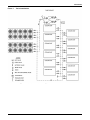
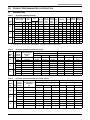
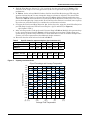
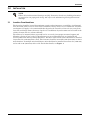
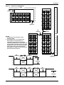
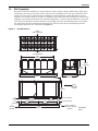
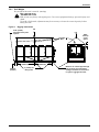
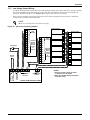
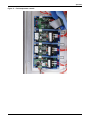
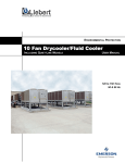
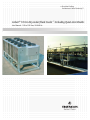
Precision Cooling
For Business-Critical Continuity™
Liebert® 10 Fan Drycooler/Fluid Cooler ™ Including Quiet-Line Models
User Manual - 120 to 150 Tons, 50 & 60 Hz
TABLE OF CONTENTS
IMPORTANT SAFETY INSTRUCTIONS . . . . . . . . . . . . . . . . . . . . . . . . . . . . . . . . INSIDE FRONT COVER
1.0
INTRODUCTION . . . . . . . . . . . . . . . . . . . . . . . . . . . . . . . . . . . . . . . . . . . . . . . . . . . . . . . . . .3
1.1
System Description and Standard Features . . . . . . . . . . . . . . . . . . . . . . . . . . . . . . . . . . . . . . . 3
1.2
Optional Features. . . . . . . . . . . . . . . . . . . . . . . . . . . . . . . . . . . . . . . . . . . . . . . . . . . . . . . . . . . . 3
2.0
PRODUCT PERFORMANCE DATA & SELECTION . . . . . . . . . . . . . . . . . . . . . . . . . . . . . . . . . .5
2.1
Standard Data . . . . . . . . . . . . . . . . . . . . . . . . . . . . . . . . . . . . . . . . . . . . . . . . . . . . . . . . . . . . . . 5
2.2
Typical Application. . . . . . . . . . . . . . . . . . . . . . . . . . . . . . . . . . . . . . . . . . . . . . . . . . . . . . . . . . . 6
2.3
Engineering Data, Calculations and Selection Procedure . . . . . . . . . . . . . . . . . . . . . . . . . . . . 6
2.4
Selection Example . . . . . . . . . . . . . . . . . . . . . . . . . . . . . . . . . . . . . . . . . . . . . . . . . . . . . . . . . . . 9
3.0
INSTALLATION . . . . . . . . . . . . . . . . . . . . . . . . . . . . . . . . . . . . . . . . . . . . . . . . . . . . . . . . . 10
3.1
Location Considerations. . . . . . . . . . . . . . . . . . . . . . . . . . . . . . . . . . . . . . . . . . . . . . . . . . . . . . 10
3.2
Site Preparation . . . . . . . . . . . . . . . . . . . . . . . . . . . . . . . . . . . . . . . . . . . . . . . . . . . . . . . . . . . . 12
3.3
Equipment Inspection Upon Delivery . . . . . . . . . . . . . . . . . . . . . . . . . . . . . . . . . . . . . . . . . . . 13
3.4
Lifting and Handling the Drycooler . . . . . . . . . . . . . . . . . . . . . . . . . . . . . . . . . . . . . . . . . . . . 13
3.4.1
3.5
Piping Connections. . . . . . . . . . . . . . . . . . . . . . . . . . . . . . . . . . . . . . . . . . . . . . . . . . . . . . . . . . 15
3.5.1
3.6
Expansion Tanks, Fluid Relief Valves and Other Devices. . . . . . . . . . . . . . . . . . . . . . . . . . . . 15
Filling Instructions. . . . . . . . . . . . . . . . . . . . . . . . . . . . . . . . . . . . . . . . . . . . . . . . . . . . . . . . . . 18
3.6.1
3.6.2
3.6.3
3.7
Unit Weight. . . . . . . . . . . . . . . . . . . . . . . . . . . . . . . . . . . . . . . . . . . . . . . . . . . . . . . . . . . . . . . . . 14
Preparing the System for Filling . . . . . . . . . . . . . . . . . . . . . . . . . . . . . . . . . . . . . . . . . . . . . . . . 18
Glycol Solutions . . . . . . . . . . . . . . . . . . . . . . . . . . . . . . . . . . . . . . . . . . . . . . . . . . . . . . . . . . . . . 18
Filling the System . . . . . . . . . . . . . . . . . . . . . . . . . . . . . . . . . . . . . . . . . . . . . . . . . . . . . . . . . . . 20
Electrical Connections . . . . . . . . . . . . . . . . . . . . . . . . . . . . . . . . . . . . . . . . . . . . . . . . . . . . . . . 20
3.7.1
3.7.2
Line Voltage . . . . . . . . . . . . . . . . . . . . . . . . . . . . . . . . . . . . . . . . . . . . . . . . . . . . . . . . . . . . . . . . 20
Low Voltage Control Wiring . . . . . . . . . . . . . . . . . . . . . . . . . . . . . . . . . . . . . . . . . . . . . . . . . . . 22
3.8
Checklist for Completing Installation . . . . . . . . . . . . . . . . . . . . . . . . . . . . . . . . . . . . . . . . . . . 23
4.0
OPERATION . . . . . . . . . . . . . . . . . . . . . . . . . . . . . . . . . . . . . . . . . . . . . . . . . . . . . . . . . . .24
4.1
Initial Startup Procedure. . . . . . . . . . . . . . . . . . . . . . . . . . . . . . . . . . . . . . . . . . . . . . . . . . . . . 24
4.1.1
4.1.2
4.1.3
Control Setpoints . . . . . . . . . . . . . . . . . . . . . . . . . . . . . . . . . . . . . . . . . . . . . . . . . . . . . . . . . . . . 24
Current-Sensing Relays . . . . . . . . . . . . . . . . . . . . . . . . . . . . . . . . . . . . . . . . . . . . . . . . . . . . . . . 26
Cold Weather Operation . . . . . . . . . . . . . . . . . . . . . . . . . . . . . . . . . . . . . . . . . . . . . . . . . . . . . . 26
5.0
SYSTEM MAINTENANCE . . . . . . . . . . . . . . . . . . . . . . . . . . . . . . . . . . . . . . . . . . . . . . . . . . 27
5.1
General Procedures . . . . . . . . . . . . . . . . . . . . . . . . . . . . . . . . . . . . . . . . . . . . . . . . . . . . . . . . . 27
5.2
Special Procedures . . . . . . . . . . . . . . . . . . . . . . . . . . . . . . . . . . . . . . . . . . . . . . . . . . . . . . . . . . 28
5.2.1
5.2.2
6.0
Drycooler Cleaning . . . . . . . . . . . . . . . . . . . . . . . . . . . . . . . . . . . . . . . . . . . . . . . . . . . . . . . . . . . 28
Maintenance Inspection Checklist . . . . . . . . . . . . . . . . . . . . . . . . . . . . . . . . . . . . . . . . . . . . . . 29
TROUBLESHOOTING . . . . . . . . . . . . . . . . . . . . . . . . . . . . . . . . . . . . . . . . . . . . . . . . . . . . . 30
i
FIGURES
Figure 1
Figure 2
Figure 3
Figure 4
Figure 5
Figure 6
Figure 7
Figure 8
Figure 9
Figure 10
Figure 11
Figure 12
Typical application . . . . . . . . . . . . . . . . . . . . . . . . . . . . . . . . . . . . . . . . . . . . . . . . . . . . . . . . . . . . . . . 4
Capacity correction factor. . . . . . . . . . . . . . . . . . . . . . . . . . . . . . . . . . . . . . . . . . . . . . . . . . . . . . . . . . 7
Pressure drop correction factor . . . . . . . . . . . . . . . . . . . . . . . . . . . . . . . . . . . . . . . . . . . . . . . . . . . . . 8
Clearance considerations . . . . . . . . . . . . . . . . . . . . . . . . . . . . . . . . . . . . . . . . . . . . . . . . . . . . . . . . . 11
Unit dimensions . . . . . . . . . . . . . . . . . . . . . . . . . . . . . . . . . . . . . . . . . . . . . . . . . . . . . . . . . . . . . . . . 12
Rigging instructions . . . . . . . . . . . . . . . . . . . . . . . . . . . . . . . . . . . . . . . . . . . . . . . . . . . . . . . . . . . . . 14
Typical piping diagram . . . . . . . . . . . . . . . . . . . . . . . . . . . . . . . . . . . . . . . . . . . . . . . . . . . . . . . . . . . 16
Piping dimensions . . . . . . . . . . . . . . . . . . . . . . . . . . . . . . . . . . . . . . . . . . . . . . . . . . . . . . . . . . . . . . . 17
Electrical field connections . . . . . . . . . . . . . . . . . . . . . . . . . . . . . . . . . . . . . . . . . . . . . . . . . . . . . . . . 21
Typical low volt wiring diagram. . . . . . . . . . . . . . . . . . . . . . . . . . . . . . . . . . . . . . . . . . . . . . . . . . . . 22
Fluid temperature controls. . . . . . . . . . . . . . . . . . . . . . . . . . . . . . . . . . . . . . . . . . . . . . . . . . . . . . . . 25
Current sensing relays . . . . . . . . . . . . . . . . . . . . . . . . . . . . . . . . . . . . . . . . . . . . . . . . . . . . . . . . . . . 26
TABLES
Table 1
Table 2
Table 3
Table 4
Table 5
Table 6
Table 7
Table 8
Table 9
Table 10
Table 11
Table 12
Table 13
Drycooler performance data . . . . . . . . . . . . . . . . . . . . . . . . . . . . . . . . . . . . . . . . . . . . . . . . . . . . . . . . 5
Drycooler performance data per circuit . . . . . . . . . . . . . . . . . . . . . . . . . . . . . . . . . . . . . . . . . . . . . . . 5
Drycooler performance data per circuit—metric. . . . . . . . . . . . . . . . . . . . . . . . . . . . . . . . . . . . . . . . 5
Maximum Liebert evaporator units per every 10 Fan Drycooler. . . . . . . . . . . . . . . . . . . . . . . . . . . 6
Specific heats for aqueous ethylene glycol solutions (Cv) . . . . . . . . . . . . . . . . . . . . . . . . . . . . . . . . . 7
Altitude correction . . . . . . . . . . . . . . . . . . . . . . . . . . . . . . . . . . . . . . . . . . . . . . . . . . . . . . . . . . . . . . . 7
Electrical specifications . . . . . . . . . . . . . . . . . . . . . . . . . . . . . . . . . . . . . . . . . . . . . . . . . . . . . . . . . . . 8
Drycooler physical data . . . . . . . . . . . . . . . . . . . . . . . . . . . . . . . . . . . . . . . . . . . . . . . . . . . . . . . . . . 13
Piping, drycoolers . . . . . . . . . . . . . . . . . . . . . . . . . . . . . . . . . . . . . . . . . . . . . . . . . . . . . . . . . . . . . . . 17
Piping specifications . . . . . . . . . . . . . . . . . . . . . . . . . . . . . . . . . . . . . . . . . . . . . . . . . . . . . . . . . . . . . 18
Volume in standard Type L copper piping. . . . . . . . . . . . . . . . . . . . . . . . . . . . . . . . . . . . . . . . . . . . 18
Ethylene glycol concentrations. . . . . . . . . . . . . . . . . . . . . . . . . . . . . . . . . . . . . . . . . . . . . . . . . . . . . 19
Control settings . . . . . . . . . . . . . . . . . . . . . . . . . . . . . . . . . . . . . . . . . . . . . . . . . . . . . . . . . . . . . . . . . 24
ii
IMPORTANT SAFETY INSTRUCTIONS
SAVE THESE INSTRUCTIONS
This manual contains important safety instructions that should be followed during the installation
and maintenance of the Liebert® 10 Fan Drycooler™. Read this manual thoroughly before attempting
to install or operate this unit.
Only properly trained and qualified personnel should move, install or service this equipment.
Adhere to all warnings, cautions and installation, operating and safety instructions on the unit and in
this manual. Follow all operating and user instructions.
! WARNING
Arc flash and electric shock hazard. Disconnect all electric power supplies and wear protective
equipment per NFPA 70E before working within electric control enclosure. Failure to comply
can cause serious injury or death.
Customer must provide earth ground to unit, per NEC, CEC and local codes, as applicable.
Before proceeding with installation, read all instructions, verify that all the parts are included
and check the nameplate to be sure the voltage matches available utility power.
The line side of the disconnect switch on the front of the unit contains live high-voltage.
The only way to ensure that there is NO voltage inside the unit is to install and open a remote
disconnect switch. Refer to unit electrical schematic.
Follow all local codes.
! WARNING
Risk of high-speed moving parts. Can cause injury or death.
Disconnect all local and remote electric power supplies before working in the unit.
Do not operate this unit with any or all cabinet panels and/or blower guards removed.
! CAUTION
Risk of contact with hot surfaces. Can cause injury.
The blower motors may become extremely hot during unit operation. Allow sufficient time for
them to cool before working within the unit cabinet. Use extreme caution and wear protective
gloves and arm protection when working on or near hot blower motors.
! CAUTION
Risk of sharp edges, splinters and exposed fasteners. Can cause injury.
Only properly trained and qualified personnel wearing appropriate safety headgear, gloves,
shoes and glasses should attempt to move the unit, lift it, remove packaging or prepare the
unit for installation.
NOTICE
Risk of clogged or leaking coolant fluid lines. Can cause equipment and building damage.
Improper installation, application and service practices can result in coolant fluid leakage
from the unit that can result in severe property damage.
Emerson Network Power® recommends installing leak detection equipment for unit and
supply lines.
1
NOTICE
Risk of a leaking coil due to freezing and/or corrosion. Can cause equipment and building
damage.
Cooling coils and piping systems that are connected to open cooling towers or other open
water/glycol systems are at high risk for freezing and premature corrosion. Fluids in these
systems must contain the proper antifreeze and inhibitors to prevent freezing and premature
coil corrosion. The water or water/glycol solution must be analyzed by a competent water
treatment specialist before startup to establish the inhibitor requirement. The water or
water/glycol solution must be analyzed every six months to determine the pattern of inhibitor
depletion. The complexity of water-caused problems and their correction makes it important
to obtain the advice of a water treatment specialist and follow a regularly scheduled
maintenance program.
NOTICE
Risk of damage from forklift. Can cause unit damage.
Keep tines of the forklift level and at a height suitable to fit below the skid and/or unit to
prevent exterior and/or underside damage.
NOTICE
Risk of improper storage. Can cause unit damage.
Keep the Liebert 10-Fan Drycooler upright and protected from freezing temperatures and
contact damage.
2
Introduction
1.0
INTRODUCTION
1.1
System Description and Standard Features
The Liebert® 10 Fan Drycooler/Fluid Cooler™ is designed for maximum heat rejection with minimum
footprint and to be used with glycol solutions for large-site installations. It has a nominal range of
150 tons of heat rejection and is ideal for rejecting the heat of multiple evaporator units. Standard
features include:
• Three different coil circuits: 068 (half), 136 (full), 272 (double). Each coil circuit is designed for a
range of specific flow rates based on the particular application.
• Coil constructed of copper tubes in a staggered pattern expanded into continuous corrugated
aluminum fins. The fins have full depth fin collars completely covering the copper tubes which are
connected to heavy-wall type L headers. Inlet coil connector tubes pass through relieved holes in
the tube sheet for maximum resistance to piping strain and vibration. Coil maximum operating
pressure is 150 PSIG (1035 kPa).
• Wire guards constructed of coated wire, in 1" x 4" pattern, mounted to protect the exposed vertical
coil surface.
• Current sensing relays are provided with customer connection to monitor change in motor current
to detect possible motor/fan failure.
• Choice of either 60 or 50Hz models as well as a Liebert Quiet-Line™ 60Hz; comes from the factory
completely assembled and pre-wired. Units are available in 208, 230, 460 and 575V, 3-phase,
60Hz, and 380/415V, 3-phase, 50Hz.
• Locking disconnect switch and fan cycling control.
• Unit frame of heavy galvanized steel for strength and corrosion resistance, divided internally into
individual fan sections by full-width baffles to prevent fan reverse windmilling when not
energized.
1.2
Optional Features
Quiet-Line
The Liebert Quiet-Line 10 Fan Drycooler includes the same features as the standard Liebert10 Fan
Drycooler, except that it has 8-pole motors in lieu of 6-pole motors for lower sound levels as well as
reduced airflow and capacity. This option is not available on 50Hz units.
Aluminum Grilles
Aluminum grilles are used for unit aesthetic and general mechanical security purposes. The
aluminum grilles extend from the base of the unit and protect the exposed coil sides.
Coil Fin Options
Pre-Coated Fin Stock provides pre-coated coil fins for added protection in corrosive environments.
Phenolic Coated Coil provides a baked phenolic coated coil for added protection in corrosive
environments.
Copper Fin/Copper Tube Coil provides coil constructed of copper fins and copper tubes.
Enclosed Motor Option
TEAO motors are totally enclosed and are used in industrial applications. They are not available for
Liebert Quiet-Line, or 575V models.
Ancillary Items
Tanks for fluid expansion, pumps, pump control panels, flow switches, shut off valves and relief
valves should also be considered for the site/installation. Since these items are custom-sized per
application, please consult with your sales representative for selection.
3
Introduction
Figure 1
Typical application
Refer to Figure 7 for a detailed installation diagram.
4
Product Performance Data & Selection
2.0
PRODUCT PERFORMANCE DATA & SELECTION
2.1
Standard Data
Table 1
Drycooler performance data
Total Heat
Rejection* @25°F
(13.9°C) ITD
Model
No. Hz
120
Btu/h
60
150
60
150
50
No. &
No. &
Size of Size of
No. of Connec- Connec- No.
Air Flow
Ft of
Internal tions
tions
of
kW gpm lps Water kPa Circuits (inlet) (outlet) Fans cfm
cmh
Flow
Rate
8.6
Pressure
Drop
Internal Shipping
Sound Volume Weight
dBA** Gal
L
Lbs
Kg
1,172,000
343
136
27.2 81.2
68
[email protected] [email protected]
10
74160 126000
65
92.8 351 5100 2313
1,447,000
424
272 17.2 15.8 47.1
136
[email protected] [email protected]
10
74160 126000
65
92.8 351 5100 2313
1,579,000
463
544 34.3 15.1 45.1
272
[email protected] [email protected]
10
74160 126000
65
92.8 351 5100 2313
1,287,000
377
136
27.3 81.5
68
[email protected] [email protected]
10
99030 168250
72
92.8 351 5100 2313
1,703,000
499
272 17.2 15.8 47.1
136
[email protected] [email protected]
10
99030 168250
72
92.8 351 5100 2313
1,924,000
564
544 34.3 15.1 45.1
272
[email protected] [email protected]
10
99030 168250
72
92.8 351 5100 2313
1,218,000
357
136
27.3 81.5
68
[email protected] [email protected]
10
82450 140080
68
92.8 351 5100 2313
1,541,000
452
272 17.2 15.8 47.1
136
[email protected] [email protected]
10
82450 140080
68
92.8 351 5100 2313
1,703,000
499
544 34.3 15.1 45.1
272
[email protected] [email protected]
10
82450 140080
68
92.8 351 5100 2313
8.6
8.6
* Ratings based on using 40% ethylene glycol @ 95°F (35°C) entering air, 120°F (48.9°C) entering glycol; 2 gpm (.13 l/s) circ.
** Sound data is for sound pressure measured @ 5 ft. (1.5m) height, 30 ft.(9.1 m) from the unit.
Table 2
Drycooler performance data per circuit
No. of Flow Rate Range
Model
Internal
min-max
No. Hz Circuits
gpm
120
60
150
60
150
50
68
136
272
68
136
272
68
136
272
Heat Rejection per ITD* (Btu/h/°F)
Pressure Drop* (ft of water)
Flow Rate per Circuit (gpm/circuit)
Flow Rate per Circuit (gpm/circuit)
68-136
136-340
272-544
68-136
136-340
272-544
68-136
136-340
272-544
1
1.5
2
1
1.5
2
29,507
45,829
56,201
30,144
50,346
65,785
29,791
47,617
59,756
39,991
53,713
60,785
42,440
61,660
73,118
41,011
56,724
65,257
46,972
57,917
63,153
51,621
68,219
77,019
48,823
61,728
68,146
8.2
5
4
8.2
5
4
8.2
5
4
16.1
9.2
8.7
16.1
9.2
8.7
16.1
9.2
8.7
27.3
23.7
15.1
27.3
23.7
15.1
27.3
23.7
15.1
* Data is based on 40% ethylene glycol solution at 115°F (46.1°C) average solution temperature expressed in Btu/h.
Table 3
Model
No.
120
150
150
Drycooler performance data per circuit—metric
Hz
60
60
50
No. of
Internal
Circuits
Flow Rate Range
min-max
lps
68
Heat Rejection per ITD* (kW/°C)
Pressure Drop* (kPa)
Flow Rate per Circuit (lps/circuit)
Flow Rate per Circuit (lps/circuit)
0.06
0.09
0.13
0.06
0.09
0.13
6-13
23.9
29.8
32.1
24.5
48.0
81.5
136
13-26
30.8
31.9
32.0
14.9
27.5
70.7
272
26-38
30.7
30.6
30.5
11.9
26.0
45.1
68
6-13
24.9
33.1
37.5
24.5
48.0
81.5
136
13-26
36.0
39.1
39.8
14.9
27.5
70.7
272
26-38
37.9
38.4
39.0
11.9
26.0
45.1
68
6-13
24.4
31.1
34.2
24.5
48.0
81.5
136
13-26
32.8
34.6
34.7
14.9
27.5
70.7
272
26-38
33.3
33.4
33.3
11.9
26.0
45.1
* Data is based on 40% ethylene glycol solution at 46.1°C (115°F) average solution temperature expressed in kW.
5
Product Performance Data & Selection
2.2
Typical Application
The most popular use for the Liebert® 10 Fan Drycooler™ is at sites with large cooling loads, such as
data center/telecom sites where multiple indoor air conditioners are used. See Table 4 for general
outline of suggested quantity of indoor units for each Liebert 10 Fan Drycooler or contact your
Emerson® representative for custom matchup. Figure 1 illustrates typical application.
Table 4
Maximum Liebert evaporator units per every 10 Fan Drycooler
Liebert Deluxe
Model 60 Hz
(50 Hz)
Liebert
Deluxe
Unit
Capacity
110 G
(111 G)
8 tons
(28.1 kW)
116 G
(121 G)
10 tons
(35.2 kW)
192 G
15 tons
(52.7 kW)
240 G
363 G
20 tons
(70.3 kW)
30 tons
(105 kW)
Total System
Maximum
Deluxe
Units/10
Fan
Drycooler
Outdoor
Ambient
Rating
gpm
(lps)
Drycooler1
Model #
12
95°F (35°C)
384
(24.2)
D*N*150**272
9
100°F (37.8°C)
288
(18.2)
6
105°F (40.6°C)
192
(12.1)
10
95°F (35°C)
380
(24.0)
7
100°F (37.8°C)
266
(16.8)
5
105°F (40.6°C)
190
(12.0)
7
95°F (35°C)
378
(23.8)
5
100°F (37.8°C)
270
(17.0)
4
105°F (40.6°C)
216
(13.6)
6
95°F (35°C)
402
(25.4)
4
100°F (37.8°C)
268
(16.9)
3
105°F (40.6°C)
201
(12.7)
4
95°F (35°C)
312
(19.7)
3
100°F (37.8°C)
234
(14.8)
2
105°F (40.6°C)
156
(9.8)
D*N*150**136
D*N*150**272
D*N*150**136
D*N*150**272
D*N*150**136
D*N*150**272
D*N*150**136
D*N*150**272
D*N*150**136
1. Ratings based on using 40% ethylene glycol @ listed outdoor ambient rating temperature, 120°F (48.9°C) entering
glycol. Selections are valid for standard or TEAO motors. Consult your local Liebert representative for Quiet-Line
selections.
2.3
Engineering Data, Calculations and Selection Procedure
An alternate, detailed procedure is available to calculate values and select the correct the 10 Fan
Drycooler(s) for the application. This can be used to assist in selecting drycoolers for applications for
ambient conditions that are not standard. Use the following steps.
1. Determine the following items to begin this procedure:
• Design outdoor ambient air temperature, Toa (F or C)
• Fluid Flow Rate, VT (gpm or lps)
• % ethylene glycol concentration
• Fluid temperatures at drycooler: Entering, Tef and leaving Tlf (F or C), or
• Total Required Heat Rejection, QRT (Btu/h or kW) and one of the fluid temperatures above
2. Find the following values using these equations and known values above:
• Initial Temperature Difference (ITD) of entering fluid to outdoor design air,
ITD = Tef - Toa
• Total Required Heat Rejection, QRT = VT * cv * (Tef - Tlf), where cv is found in Table 5, or
• Leaving fluid temperature, Tlf = Tef - QRT / (VT * cv) where cv is found in Table 5.
3. Find the Average Fluid Temperature, Tf,avg = (Tef + Tlf) / 2
4. Find Required Heat Rejection per ITD, QRITD = QRT / (ITD * f), where f is the capacity correction
factor found in Figure 2.
5. Using Table 2 columns titled Flow Rate Range and Heat Rejection per ITD, choose the Drycooler
Model matching application fluid flow rate and meeting/exceeding the required Heat Rejection
per ITD, QRITD from Step 4.
6
Product Performance Data & Selection
6. Find the Flow Rate per Circuit, VC = VT / circuits for the drycooler selected in Table 2. This
should be in the range of 1.0 to 2.0 gpm/circuit (0.06 to 0.13 lps/circuit) for proper long-term
performance.
7. In Table 2, for the selected Model Number, find the Actual Heat Rejection per ITD using the
gpm/circuit from Step 6. You may interpolate between columns as required. The Actual Heat
Rejection should be equal to or greater than per ITD, QRITD (higher altitude application sites
should use Table 6 correction factors to reduce Actual Heat Rejection results). If it is less, repeat
process from Step 5 using a larger model. If 10 Fan Drycooler solution is oversized, lower capacity
drycoolers are available and may be considered as an alternative solution.
8. Calculate the Total Actual Heat Rejection, QA, for the drycooler, using the Actual Heat Rejection
per ITD (Step 7) and actual ITD and correcting for % glycol and AFT (see Figure 2).
QA = QAITD * ITD * f
9. After selecting a model, look up the unit’s Pressure Drop in Table 2. Multiply this pressure drop
by the correction factor found in Figure 3. If the resulting pressure drop is higher than your
system design, go back to Step 5 and select a model with more circuits or consider multiple units.
Contact your sales representative for additional design assistance.
10. Electrical data for model selected is found in Table 7.
Table 5
% Ethylene Glycol
0%
10%
20%
30%
40%
50%
Btu/h/gpm°F
500
490
480
470
450
433
kW/lps°C
4.18
4.09
4.01
3.93
3.76
3.62
Table 6
Altitude correction
Altitude - Feet (M)
0
(0)
1000
(305)
2000
(610)
5000
(1525)
8000
(2440)
12000
(3660)
15000
(4575)
Correction Factor
1.000
0.979
0.960
0.900
0.841
0.762
0.703
Capacity correction factor
Glycol Percentage and Average Temperature
1.08
0
1.07
10
1.06
1.05
20
1.04
30
1.03
40
1.02
1.01
50
1.00
Glycol Percentage
Correction Factor
Figure 2
Specific heats for aqueous ethylene glycol solutions (Cv)
0.99
0.98
0.97
0.96
0.95
0.94
°F 80
(°C) (26.7)
100
(37.8)
120
(48.9)
140
(60)
Average Fluid Temperature
7
160
(71.1)
Product Performance Data & Selection
Pressure drop correction factor
1.15
Glycol Percentage and Fluid Temperature
Glycol Percentage
Figure 3
Correction Factor
1.10
1.05
1.0
0.95
50
40
0.90
30
20
0.55
10
0
0.80
°F 80
(°C) (26.7)
100
(37.8)
120
(48.9)
140
(60)
160
(71.1)
Average Fluid Temperature
Table 7
Electrical specifications
60 Hz
VoltagePhase
50 Hz
208-3
230-3
460-3
575-3
380/415-3
Drycooler
Motor Type FLA MCA OPD FLA MCA OPD FLA MCA OPD FLA MCA OPD FLA MCA OPD
Model
D0N*150
STANDARD 70
72
90
70
72
90
35
36
45
28
30
35
35
36
40
DTN*150
TEAO
70
72
90
70
72
90
35
36
45
n/a
n/a
n/a
n/a
32
35
DGN*120
QuietLine
48
50
60
48
50
60
24
25
30
28
30
35
24
25
30
8
Product Performance Data & Selection
2.4
Selection Example
For the following example, English (I-P) units will be used. Metric units are also provided in the
tables and figures.
Find a drycooler to cool 340 gpm of 20% ethylene glycol/water solution from 125°F to 115°F.
Application is near sea level and has an outdoor design air temperature of 95°F.
1. Assume the following values:
• Toa = 95°F
• VT = 340 gpm
• 20% ethylene glycol
• Tef = 125°F
• Tlf = 115°F
2. Initial temperature difference, ITD = Tef - Toa = 125 - 95 = 30°F
• Since Tef is known, calculate Total Required Heat Rejection, QRT = VT * cv * (Tef - Tlf)
• Using Table 5, cv = 480 for 20% ethylene glycol.
• QRT = 340 gpm * 480 Btu/h / gpm°F * (125°F - 115°F) = 1,632,000 Btu/h
3. Average Fluid Temperature, Tf,avg = (Tef + Tlf) / 2 = 125°F + 115°F) / 2 = 120°F
4. Required Heat Rejection per ITD, QRITD = QRT / (ITD * f), where f is found from Figure 2.
• Using Figure 2, f = 1.04 for 120°F and 20% EG concentration.
• QRITD = 1,632,000 Btu/h / (30°F * 1.04) = 52,300 Btu/h / °F
5. Locate Model Number(s) in Table 2, matching flow rate of 340 gpm and meeting or exceeding
52,300 Btu/h / °F. Either Model 120 with 272 circuits or the Model 150 with 272 circuits matches
the flow rate requirements and meets or exceeds the Required Heat Rejection per ITD. For this
example, Model 150 will be chosen to complete the procedure.
6. Flow rate per circuit, VC = VT / circuits = 340 gpm / 272 circuits = 1.25 gpm/circuit. This is within
the 1.0 to 2.0 gpm/circuit range.
7. Using Table 2, the actual Heat Rejection per ITD, QAITD for Model 150 with 272 circuits @ 1.25
gpm/circuit is 69,526 Btu/h / °F, which exceeds our Required Heat Rejection per ITD of 52,300
Btu/h / °F. No correction for altitude is required.
8. Total Actual Heat Rejection for the drycooler, QA = QAITD * ITD * f, where f is found in Figure 2.
• QA = 69,526 Btu/h / °F * 30°F * 1.04 = 2,169,211 Btu/h
9. Pressure drop for 1.25 gpm/circuit is 6.25 ft., water using Table 2 for 40% ethylene glycol and
Tf,avg = 115°F. Use Figure 3 to find correction factor for the pressure drop for 20% ethylene glycol
and Tf,avg = 120° F. Therefore, the pressure drop will be 6.259 * 0.93 = 5.8 ft., water.
10. Using Table 7 and Drycooler Model D0N*150 with a 460 VAC, 3-phase, 60 Hz motor, the
electrical requirements will be FLA = 31 amps, WSA = 32 amps and OPD = 35 amps.
9
Installation
3.0
INSTALLATION
NOTE
Follow all unit dimensional drawings carefully. Determine whether any building alterations
are required to run piping and wiring. Also refer to the submittal engineering dimensional
drawings.
3.1
Location Considerations
The drycooler should be located for maximum security and maintenance accessibility. Avoid ground
level sites with public access or areas which contribute to heavy snow or ice accumulations. To assure
an adequate air supply, it is recommended that drycoolers be located in a clean air area, away from
loose dirt and foreign matter that may clog the coil. In addition, drycoolers must not be located in the
vicinity of steam, hot air, or fume exhausts.
The unit may be mounted either at ground level or on a roof, given proper structural support and
following a review of local codes. Pit installations are not recommended. Air re-circulation will
severely affect unit and/or system performance. For these same reasons, units should not be installed
closer than 72" (1829 mm) from a wall. This clearance should be increased to 96" (2438 mm) in corner
wall situations. In multiple unit installations, units should not be installed closer than 72" (1829 mm)
end to end or 96" (2438 mm) side to side. For further details, see Figure 4.
10
Installation
Figure 4
Clearance considerations
Wall
96"
(2438mm)
96"
(2438mm)
96"
(2438mm)
72"
(1829mm)
Wall
NOTES:
1. All dimensions are minimum, unless
otherwise noted.
2. Pit installations are not recommended.
Recirculation of hot discharge air in
combination with surface air turbulence
cannot be predicted. Hot air recirculation will
severely affect unit efficiency and can cause
high-pressure trips or fan motor temperature
trips. Supplier will not be responsible for
ducting fans to a higher level to alleviate the
above-mentioned conditions.
96"
(2438mm)
96"
(2438mm)
72"
(1829mm)
84"
(2134mm)
96"
(2438mm)
96"
(2438mm)
96"
(2438mm)
84"
(2134mm)
11
Installation
3.2
Site Preparation
Drycoolers should be installed in a level position to assure proper venting and drainage. This space
should have all services (electrical, drain, water) in close proximity. Also, the space should be level
and free of loose gravel, sand, flooring or roofing. For roof installation, mount drycoolers on steel
supports in accordance with local codes. To minimize sound and vibration transmission, mount steel
supports across load-bearing walls. For ground installations, a concrete pad is sufficient to carry the
load. The base should be at least 2 inches (51 mm) higher than the surrounding grade and 2 inches
(51 mm) larger than the dimensions of the unit base. The drycooler base has mounting holes for
securing the drycooler once installed. See Figure 5.
Figure 5
Unit dimensions
Airflow
Side and Bottom
Airflow
Side and Bottom
184"
(4674mm)
93-1/8"
(2365mm)
88-1/16"
(2237mm)
216"
(5486mm)
86"
(2184mm)
6"
(152mm)
86"
(2184mm)
6"
(152mm)
7-1/2"
(191mm)
3"
(76.2mm)
diameter
86"
(2184mm)
103-1/2"
(2629mm)
94"
(2388mm)
94"
(2388mm)
UNIT
ANCHOR
PLAN
20-1/2" (521mm)
20-1/2" (521mm)
11/16" (17.46mm)
mounting hole diameter
6 places
216"
(5486mm)
12
DPN000985
REV. 0
Installation
Table 8
3.3
Drycooler physical data
Model #
No. of
Fans
CFM (CMH)
60Hz.
CFM (CMH)
50Hz.
Coil Internal
Vol. Gal (L)
Net Weight
Lb (kg)
D*N*150**068
10
99030
(168250)
82450
(140080)
92.8 (351)
5100 (2313)
D*N*150**136
10
99030
(168250)
82450
(140080)
92.8 (351)
5100 (2313)
D*N*150**272
10
99030
(168250)
82450
(140080)
92.8 (351)
5100 (2313)
DGN*120**068
10
74160
(126000)
N/A
92.8 (351)
5100 (2313)
DGN*120**136
10
74160
(126000)
N/A
92.8 (351)
5100 (2313)
DGN*120**272
10
74160
(126000)
N/A
92.8 (351)
5100 (2313)
Equipment Inspection Upon Delivery
When the Liebert® 10 Fan Drycooler™ arrives, inspect it for any visible or concealed damage. Do not
accept a damaged unit from the shipper!
NOTE
Any damage caused in transit must be reported immediately to the carrier and a damage
claim filed with a copy sent to your sales representative. Failure to do so may result in an
inability to recover costs for damage.
Before removing the drycooler from the truck/container, review the previous section, 3.2 - Site
Preparation.
NOTICE
Risk of exposure to freezing temperatures. Can cause equipment damage.
If the drycooler is not installed immediately upon receipt, special storage precautions should
be taken. It is recommended that the unit be stored in a dry, heated place. Do not store the
unit at temperatures below 36°F (2.2°C). If the storage temperature is below 36°F (2.2°C),
water vapor can condense in the coil, freeze and cause permanent damage. Failure to store
unit properly will void the warranty.
3.4
Lifting and Handling the Drycooler
! WARNING
Risk of unit very heavy unit tipping over. Can cause equipment damage, personal injury and
death.
Do not unload the drycooler with a forklift. The drycooler’s high center of gravity makes it a
tipping hazard. Further, tilted forks may damage the drycooler. Use chains and hooks when
removing the unit from the truck and when moving it between areas of equal height.
Riggers are required to lift the unit into place. Refer to Figure 6 for lift locations. Any time the unit is
lifted, use slings or chains (with spreader bars) attached to the three lifting eyes on either side of the
unit base. Do not allow any part of the lifting apparatus to bear against the coil fins. All lifting
apparatus must also clear the fan guards on the top of the unit.
13
Installation
3.4.1
Unit Weight
Dry weight of the unit is 5100 lb. (2313kg).
! WARNING
Risk of unit very heavy unit tipping over. Can cause equipment damage, personal injury and
death.
To avoid a tilt hazard, adjustment may be necessary to locate the center of gravity before
lifting the unit.
Figure 6
Rigging instructions
2-7/8" (73mm)
removable chain pulls
2 places
Lift
Lift
Spreader
Bars
94"
(2388 mm)
5-29/32"
(150mm)
Must
clear top
of fan
grilles
94"
(2388 mm)
Must use 2" nominal pipe through
unit for slings to prevent base
damage. Do NOT use small holes
in legs for rigging these units
3" (76mm) dia.
lifting holes
14
Installation
3.5
Piping Connections
See Figure 7 for a typical piping diagram. See Figure 8 piping locations.
NOTICE
Risk of overpressurization. Can cause equipment damage.
To avoid the possibility of burst pipes, it is necessary to install a relief valve in the system.
This valve may be obtained from your supplier as an option or may be sourced from another
vendor. Galvanized pipe must not be used in glycol systems. To help prevent piping failures,
supply and return lines must be supported such that their weight does not bear on the piping
of the unit or pumps.
NOTE
Units are shipped pressurized with a 30 psig dry air holding charge.
It is recommended that manual service shutoff valves be installed at the supply and return
connections to each unit. This enables routine service and/or emergency isolation of the unit. In
addition, multiple pump packages require a check valve at the discharge of each pump to prevent
backflow through the standby pump(s).
Emerson® recommends installing filters/strainers in the supply line. These filters or strainers should
be a type that can be easily replaced or cleaned, with 16-20 mesh screen. These filters extend the
service life of the drycooler and the system’s pumps.
Emerson recommends installing hose bibs at the lowest point of the system to facilitate filling.
Consideration of the minimum glycol temperature to be supplied from the drycooler will determine if
the glycol supply and return lines must be insulated toprevent condensation on the glycol lines in low
ambient conditions.
All fluid piping must comply with local codes. Care in sizing pipes will help reduce pumping power
and operating costs.
3.5.1
Expansion Tanks, Fluid Relief Valves and Other Devices
An expansion tank must be provided for expansion and contraction of the fluid due to temperature
change in this closed system. Vents are required at system high points to vent trapped air when
filling the system. A relief valve is also a necessary piping component.
Depending on the complexity of the system, various other devices may be specified. Pressure gauges,
flow switches, automatic air separator, tempering valves, standby pumps and sensors for electrical
controls are just a few of these devices.
NOTICE
Risk of burst pipes and leaking water from freezing temperatures. Can cause equipment and
building damage.
Immediately following the use of water for leak testing or system cleaning, charge the tested
system with the proper percentage of glycol and water for the coldest design ambient
expected. Complete system drain-down cannot be ensured, and damage to the system could
result from freezing of residual water.
15
Installation
Figure 7
Typical piping diagram
16
Installation
Figure 8
Piping dimensions
NOTE
Tolerance of ±1" (25.4mm)
on all piping dimensions
B
A
68-5/8"
(1743mm)
Outlet
Typ.
50-3/16"
(1275mm)
Inlet
Typ.
14-1/2"
(369mm)
Outlet
B
A
22"
(559mm)
Inlet 63-1/2"
(1613mm)
Intlet
71-7/8"
(1825mm)
Outlet
Table 9
DPN000986
REV. 0
Piping, drycoolers
Connection Sizes (ODS)
Model #.
No. Fans
No. of
Internal
Circuits
D*N*150**068
10
68
2
2
2.625" (66.7mm)
2.625" (66.7mm)
D*N*150**136
10
136
2
2
4.125'' (104.8mm)
4.125'' (104.8mm)
D*N*150**272
10
272
2
2
4.125'' (104.8mm)
4.125'' (104.8mm)
DGN*120**068
10
68
2
2
2.625" (66.7mm)
2.625" (66.7mm)
DGN*120**136
10
136
2
2
4.125'' (104.8mm)
4.125'' (104.8mm)
DGN*120**272
10
272
2
2
4.125'' (104.8mm)
4.125'' (104.8mm)
No. of
Inlets
No. of
Outlets
(A) Inlet
(B) Outlet
17
Installation
Table 10
Piping specifications
Model
No. of Internal
Circuits
D0N*150**
68
DTN*150**
136
DGN*120**
272
No. of
Inlets (A)
No. of
Outlets (B)
Connection Sizes, Inlet
and Outlet OD (in.) *
Coil Internal
Volume, Gal. (l)
2.625
2
2
4.125
92.8 (351)
*Cut off closed end of connection tube; connect couplings and elbows as required.
Table 11
Volume in standard Type L copper piping
Diameter (in.)
Volume
Outside
Inside
gal/ft
l/m
1-3/8
1.265
0.065
0.81
1-5/8
1.505
0.092
1.15
2-1/8
1.985
0.161
2.00
2-5/8
2.465
0.248
3.08
3-1/8
2.945
0.354
4.40
3-5/8
3.425
0.479
5.95
4-1/8
3.905
0.622
7.73
3.6
Filling Instructions
3.6.1
Preparing the System for Filling
It is important to remove any dirt, oil or metal filings that may contaminate the cooling system piping
in order to prevent contamination of the fresh glycol solution and fouling of the drycooler piping. The
system should be flushed thoroughly using a mild cleaning solution or high-quality water and then
completely drained before charging with glycol. Cleaning new systems is just as important as
cleaning old ones. New systems can be coated with oil or a protective film; dirt and scale are also
common. Any residual contaminants could adversely affect the heat transfer stability and
performance of your system. In many cases, in both old and new systems, special cleaners are needed
to remove scale, rust and hydrocarbon foulants from pipes, manifolds and passages. Clean heat
transfer surfaces are important in maintaining the integrity of the heating/cooling system. For more
information on cleaners and degreasers, contact your sales representative. Follow the manufacturer’s
instructions when using these products.
Calculate the internal volume of the system as closely as possible. The Liebert® 10 Fan Drycooler™
volume, not including the load or field-supplied piping, is 92.8 gallons (351 l). Use Table 11 for
field-installed piping volumes.
3.6.2
Glycol Solutions
NOTE
Glycol solutions should be considered for the protection of the coil. When glycol solutions are
not used, damage can occur either from freezing or from corrosion from water.
When considering the use of any glycol products in a particular application, you should review the
latest Material Safety Data Sheets and ensure that the use you intend can be accomplished safely.
For Material Safety Data Sheets and other product safety information, contact the supplier nearest
you. Before handling any other products mentioned in the text, you should obtain available product
safety information and take necessary steps to ensure safety of use.
18
Installation
NOTICE
Risk of improper handling of glycol. Can cause environmental damage.
When mishandled, glycol products pose a threat to the environment. Before using any glycol
products, review the latest Material Safety Data Sheets and ensure that you can use the
product safely. Glycol manufacturers request that the customer read, understand and comply
with the information on the product packaging and in the current Material Safety Data
Sheets. Make this information available to anyone responsible for operation, maintenance
and repair of the drycooler and related equipment.
NOTICE
Risk of using improper glycol. Can cause equipment damage.
Automotive antifreeze is unacceptable and must NOT be used.
No chemical should be used as or in a food, drug, medical device, or cosmetic, or in a product or
process in which it may contact a food, drug, medical device, or cosmetic until the user has
determined the suitability and legality of the use. Since government regulations and use conditions
are subject to change, it is the user's responsibility to determine that this information is appropriate
and suitable under current, applicable laws and regulations.
Typical inhibited formula ethylene glycol and propylene glycol manufacturers and suppliers are
Union Carbide (Ucartherm) and Dow Chemical (Dowtherm SR-1, Dowfrost). These glycols are
supplied with corrosion inhibitors and do not contain a silicone anti-leak formula. Commercial
ethylene glycol, when pure, is generally less corrosive to the common metals of construction than
water itself. Aqueous solutions of these glycols, however, assume the corrosivity of the water from
which they are prepared and may become increasingly corrosive with use when not properly
inhibited.
There are two basic types of additives:
• Corrosion inhibitors and
• Environmental stabilizers
The corrosion inhibitors function by forming a surface barrier that protects the metals from attack.
Environmental stabilizers, while not corrosion inhibitors in the strictest sense of the word, decrease
corrosion by stabilizing or favorably altering the overall environment. An alkaline buffer, such as
borax, is a simple example of an environmental stabilizer, since its prime purpose is to maintain an
alkaline condition (pH above 7).
The percentage of glycol to water must be determined by using the lowest design outdoor temperature
in which the system is operating. Table 12 indicates the solution freeze point at several c
concentration levels of ethylene glycol. Propylene glycol concentrations should be 1% higher than
ethylene glycol table values to find the freeze point. For example, 41% propylene glycol freezes at 10°F.
Table 12
Ethylene glycol concentrations
% Glycol by Volume
Freezing Point °F (°C)
Apparent Specific Gravity
@ 50°F (10°C)
0*
10
20
30
40
50
32 (0)
25 (-3.9)
16 (-8.9)
5 (-15.0)
-10 (-23.3)
-32 (-35.5)
1
1.014
1.028
1.042
1.057
1.071
* A minimal amount of glycol should be considered for inhibitive coil protection.
NOTICE
Risk of poor water quality. Can cause equipment damage.
The quality of water used for dilution must be considered because water may contain
corrosive elements that reduce the effectiveness of the inhibited formulation. Surface water
that is classified as soft (low in chloride and sulfate ion content—less than 100 ppm each)
should be used.
19
Installation
3.6.3
Filling the System
Emerson® recommends installing hose bibs at the lowest point of the system.
When filling a glycol system, keep air to a minimum. Air in glycol turns to foam and is difficult and
time-consuming to remove. (Anti-foam additives are available and may be considered.)
Open all operating systems to the loop. With the top vent(s) open, fill the system from the bottom of
the loop. This will allow the glycol to push the air out of the top of the system, minimizing trapped air.
Fill to approximately 80% of calculated capacity. Fill slowly from this point, checking fluid levels until
full.
NOTE
For glycol solution preparation and periodic testing, follow manufacturer’s recommendations.
Do not mix products of different manufacturers.
3.7
Electrical Connections
Each unit is shipped from the factory with all internal unit wiring completed. Refer to the electrical
schematic when making connections. All wiring must be done in accordance with the National
Electric Code and all local and state codes.
! WARNING
Risk of electric shock. Can cause injury or death. Disconnect all local and remote electric
power supplies before working within the unit.
The fans may start unexpectedly. The line side of the factory disconnect remains energized
when the disconnect is Off. Use a voltmeter to confirm that the electric power is turned Off
before making any electrical connections.
3.7.1
Line Voltage
Drycooler rated voltage should be verified with available power supply upon receipt of unit but before
installation. Refer to the unit electrical schematic and serial tag for specific electrical requirements.
All wiring must be done in accordance with the National Electric Code as well as all local and state
codes.
! CAUTION
Risk of using improper wire. Can cause equipment damage or a safety hazard from
overheated wire and/or connections.
Size the system electrical service for the total of all drycoolers and ancillary components
FLA/WSA/OPD. Unit-specific wiring diagrams are provided on each unit. Use copper
wiring only. Make sure that all connections are tight.
Line voltage electrical service is required for all drycoolers at the location of the drycooler. The power
supply does not necessarily have to be the same voltage supply as required by the indoor unit for
which the drycooler operates. This power source may be 208, 230, 460 or 575V 60Hz; or 380/415V
50Hz. A unit disconnect is standard. However, a site disconnect may be required per local code to
isolate the unit for maintenance. Route the supply power to the site disconnect switch and then to the
unit. Route the conduit through the hole provided in the cabinet. Connect earth ground to lug
provided near terminal board. For units with multi-voltage transformer, the transformer connections
should match (change if necessary) the local power supply. See Figure 9.
20
Installation
Figure 9
Electrical field connections
Remote Start Contact
Remote Alarm Contacts
On Loss of Current
Control Fuse
and Fuse Block
Current-Sensing
Relay Option
High-Voltage
Fuses and
FuseBlocks
Factory-Installed
Disconnect Switch
70
71
80
81
83
84
85
86
101
102
103
104
105
Ground
Lug
Power
Control
Switch
L1 L2 L3
Thermostat
1st and 2nd
Stage and
Display
Modules
Contactor
Entrance Field-Supplied
Low Voltage Class 2 Wiring
7/8" (22mm)
Knockout
Electric Service (not by
(3 Places)
Emerson®) Three-Phase for
all models; Provide in
accordance with National
and Local Electrical Codes)
21
Installation
3.7.2
Low Voltage Control Wiring
A control interlock between the drycooler and the heat load(s) will require 24V Class 2 copper wiring
for remote On/Off sequencing of the drycooler with the load. Refer to the electrical schematic for
wiring to Terminals 70 & 71. See Figure 10 for typical low-volt system wiring.
If the current sensing relay option is provided, 24V Class 2 wiring will be necessary to make the
connections to monitor motor operation.
NOTE
Make sure all electrical connections are tight.
Figure 10 Typical low volt wiring diagram
70
71
Cooling Unit # __
Remote
Start
Contact
80
Cooling Unit # __
81
83
70
84
71
85
86
Flow Switch
101
102
103
Optional
Remote
Alarms
Contact
on Loss
of
Current
Cooling Unit # __
80
81
83
84
85
104
86
105
101
102
Remote
Alarm
Remote
Start
Contact
103
Cooling Unit # __
Optional
Remote
Alarms
Contact
on Loss
of
Current
104
105
Cooling Unit # __
Cooling Unit # __
70
71
70
71
70
71
70
71
70
71
70
71
70
Cooling Unit # __
71
70
Cooling Unit # __
71
70
Cooling Unit # __
71
70
Cooling Unit # __
71
70
Cooling Unit # __
71
70
Cooling Unit # __
24 50
74 77
Standby Pump
On Alarm
(Dry Contact)
Flow Switch
Connection
71
80 81
82 83
Drycooler
Interlock
NOTES:
1. All 24 volt control wiring is shown
in dashed lines—by others.
2. Refer to individual wiring schematics
for power wiring.
70 71
Heat Rejection
Interlock
TYPICAL PUMP CONTROL PANEL
22
Installation
3.8
Checklist for Completing Installation
NOTE
After installation, proceed with the following list to verify that the installation is complete.
Complete and return the Warranty Inspection Check Sheet which is shipped with the unit and
return to the address indicated on the check sheet.
___ 1. Proper clearances for service access have been maintained around the equipment.
___ 2. Equipment is level and mounting fasteners are tight.
___ 3. Piping completed to coolant loop.
___ 4. All piping connections are tight as well as secured and isolated for vibration reduction.
___ 5. All piping connections inspected for leaks during initial operation.
___ 6. Line voltage to power wiring matches equipment nameplate.
___ 7. Power wiring connections completed to disconnect switch, including earth ground.
___ 8. Power line circuit breakers or fuses have proper ratings for equipment installed.
___ 9. Control wiring connections completed to heat loads/evaporator(s), including wiring to optional
controls.
___ 10. All wiring connections are tight.
___ 11. Foreign materials have been removed from in and around all equipment installed (shipping
materials, construction materials, tools, etc.).
___ 12. Fans rotate freely and in correct direction without unusual noise and discharge the air
upwards.
___ 13. Glycol has been added to the drycooler to prevent freeze damage.
23
Operation
4.0
OPERATION
! WARNING
Risk of electric shock. Can cause injury or death. Disconnect all local and remote electric
power supplies before working within the unit.
The fans may start unexpectedly. Disconnect the power supply before working on the unit.
Line side of factory disconnect remains energized when the disconnect is Off. Use a voltmeter
to make sure power is turned off before checking any electrical connections or functions.
4.1
Initial Startup Procedure
Refer to 3.8 - Checklist for Completing Installation and verify that all installation items have
been completed prior to proceeding.
Turn the unit ON. Check the fans for proper rotation (air discharging up). Check the pumps for
proper rotation.
NOTICE
Risk of overheated pumps. Can cause equipment damage.
Do not run pumps without fluid in the system. Pump seals require fluid to keep them cool;
running them for any amount of time will damage the seals, which may cause a failure.
4.1.1
Control Setpoints
The fluid temperature controls should be set according to Table 13 for standard cooling only or freecooling GLYCOOL applications. See Figure 11.
Table 13
Control settings
Heat
Rejection
Method
Fluid
Temperature
Control
Setpoint
1TAS
68°F (20°C)
-
Standard
1STG
-
5°F (2.8°C)
2STG
-
1TAS
Free-Cooling
(GLYCOOL)
Offset
Differential
Open
Close
68°F (20°C)
80°F (26.7°C)
12°F (6.7°C)
73°F (22.8°C)
85°F (29.4°C)
10°F (5.6°C)
78°F (25.6°C)
90°F (32.2°C)
42°F (5.6°C)
-
42°F (5.6°C)
50°F (10°C)
1STG
-
2°F (1.1°C)
44°F (6.7°C)
52°F (11.1°C)
2STG
-
4°F (2.2°C)
46°F (7.8°C)
54°F (12.2°C)
24
8°F (4.4°C)
Operation
Figure 11
Fluid temperature controls
25
Operation
4.1.2
Current-Sensing Relays
If supplied, be sure that the current-sensing relays (CSR) are wired as per the wiring schematic using
24V Class 2 copper wiring. When the thermostat closes, a 24-volt signal will be sent to the relevant
terminals of the CSR. When this occurs, a time delay starts, allowing the amperage to be sensed on
the load side of the contactors.
First, set selection under amperage on selector switch, then start all fans. Set the trip delay for 50%.
Disconnect one of the load side wires from a fan being monitored by the control. Turn the
potentiometer until the LED is lit. Reconnect the fan wire. Check and repeat for the other circuits. Be
sure to set the fluid temperature controls as per the specifications, as illustrated within the unit
electrical schematic (supplied with the unit), or refer to 4.1.1 - Control Setpoints and Table 13. See
Figure 12 for current sensing relay layout.
Figure 12 Current sensing relays
4.1.3
Cold Weather Operation
Glycol solution should be used for operation of units located where outdoor ambients will include
temperatures at or below freezing. Refer to the installation sections referring to piping (3.5 - Piping
Connections) and glycol solutions (3.6.2 - Glycol Solutions) for further details.
26
System Maintenance
5.0
SYSTEM MAINTENANCE
! WARNING
Risk of electric shock. Can cause injury or death. Disconnect all local and remote electric
power supplies before working within the unit.
The fans may start unexpectedly. Disconnect power supply before working on unit. Line side
of factory disconnect remains energized when disconnect is off. Use a voltmeter to make sure
power is turned off before checking any electrical connections or functions
5.1
General Procedures
NOTE
When ordering replacement parts for equipment, it is necessary to specify the unit’s model
number, serial number and voltage. Record those numbers in the spaces below.
• Model Number___________________
• Serial Number___________________
• Voltage__________________________
Periodic attention is necessary for continued satisfactory operation of your unit. A daily inspection of
the system should be made to verify that the unit is performing satisfactorily. It is suggested that a
daily log be maintained recording inlet and outlet coolant temperature, ambient temperature and the
coolant pressure gauge readings. The coolant sight glass should be checked and the fans checked for
unusual sounds which may indicate wear or future trouble.
Monthly inspections should include removal and cleaning of strainer, and cleaning and inspection of
coil. The coil can be cleaned with water, compressed air or steam as required. During monthly
inspections, it is also wise to check the coolant to assure sufficient glycol in the mixture to prevent
freeze-up. Each fan motor amp draw should be checked. If performance or operation problems are also
detected, refer to 6.0 - Troubleshooting for required action. Use copies of 5.2.2 - Maintenance
Inspection Checklist
Restricted air flow through the drycooler coil will reduce the operating efficiency of the unit and can
result in high fluid temperatures and loss of cooling. Clean the drycooler coil of all debris that will
inhibit air flow. This can be done with compressed air or a commercial coil cleaner. Check for bent or
damaged coil fins and repair as necessary. In winter, do not permit snow to accumulate around the
sides or underneath the drycooler.
Check all fluid lines and capillaries for vibration isolation. Support as necessary. Visually inspect all
fluid lines for signs of fluid leaks.
Inspect the motor/fan assemblies to insure bearings are free and the motor is secure within the
mount.
The glycol level in drycooler systems must be periodically checked. At the high point of the system,
check for:
• Positive pressure
• Air to be vented
• An unclogged expansion tank
• Proper concentration of inhibitors and antifreeze
The first three checks may give an indication of leaks in the system.
27
System Maintenance
5.2
Special Procedures
5.2.1
Drycooler Cleaning
Keeping the outdoor drycooler coils clean is an important factor in maintaining peak efficiency,
reliability and long life of the equipment. It is much easier to keep up on frequent cleanings rather
than wait until heavy build up has occurred which may create head pressure problems with the
evaporator units.
When to Clean
Normal conditions typically dictate cleaning twice a year, spring and fall. On-site or area conditions
such as cottonwood trees, construction, etc., can increase cleaning frequency. On your standard
bimonthly or quarterly preventive maintenance schedule, a visual inspection of the coil is
recommended to monitor conditions.
What to Use
The best overall condenser coil cleaner to use is plain water. If the coil has been maintained and
cleaned at regular intervals, water is sufficient to remove dirt and debris from the fins. Heavy buildup
on the exterior of the fins can be removed with a brush. Water pressure from a garden hose and
sprayer usually works well. If a pressure washer is used, make sure the equipment is set to a lower
pressure setting and that the nozzle is set to the fan spray, not stream. Otherwise, damage to the fins
could result. If a cleaner is required, Emerson® recommends using a non-acidic type cleaner. Acidtype cleaners can be aggressive to the coil fins as well as surrounding areas. Many sites do not allow
the use of acidic cleaners for environmental reasons.
How to Clean
The best way to clean coils is from the inside out. This requires removing the coil guards or grilles (if
provided), the fan guards and blades to access the coil surface. The sprayer can then be worked across
the coil pushing the dirt and debris out. Although this does extend the time involved, the results are
well worth it. This method should be used at least once a year. Spraying the coil from the outside
repeatedly can push a majority of the dirt to the inner section of the fins and continue to restrict air
flow. Keep in mind you may not have the luxury of shutting the unit(s) down for an extended time. A
scheduled shutdown with the operator may be in order. If using a cleaner along with the spraying
process, follow recommended manufacturer instructions and be sure to rinse the coil thoroughly. Any
residue left on the coil can act as a magnet to dirt.
28
System Maintenance
5.2.2
Maintenance Inspection Checklist
Date:____________________________________
Prepared By:____________________________________
Model #:_________________________________
Serial Number:__________________________________
NOTE
Regular inspections are necessary to assure proper cleanliness of the cooling fins. Should
inspection reveal dirt or corrosion, appropriate cleaning should be performed.
Monthly
Drycooler
Semiannually
Drycooler
___ 1. Coil surfaces free of debris
___ 1. Complete all monthly items
___ 2. Fans/grilles free of debris
___ 2. Piping in good condition
___ 3. Fan motors securely mounted
___ 3. Piping secure
___ 4. Motor bearings in good
condition
___ 4. Wash coil as needed
___ 5. No water/glycol leaks
Pump Package
___ 1. Complete all monthly items
Pump Package
___ 2. Test changeover operation
___ 1. Pump rotation
___ 3. Pump #1 amp draw __________
Pump #2 amp draw __________
Pump #3 amp draw ___________
___ 2. Pump securely mounted
___ 3. No water/glycol leaks
___ 4. Glycol level and general condition
___ 4. No abnormal noises
___ 5. Glycol freeze point ____°F and pH ____
___ 6. Check all electrical connections
___ 7. Check contactors for pitting
Drycooler Electric Panel
___ 1. Check all electrical connections
___ 2. Check contactors for pitting
___ 3. Operational sequence/setpoints
Fan Motors
___ 1. Motor #1 amp draw __________ amps
___ 2. Motor #2 amp draw __________ amps
___ 3. Motor #3 amp draw __________ amps
___ 4. Motor #4 amp draw __________ amps
___ 5. Motor #5 amp draw __________ amps
___ 6. Motor #6 amp draw __________ amps
___ 7. Motor #7 amp draw __________ amps
___ 8. Motor #8 amp draw __________ amps
___ 9. Motor #9 amp draw __________ amps
___ 10. Motor #10 amp draw _________ amps
Notes:
Signature: ______________________________________________________________________
Make photocopies of this form for your records
29
Troubleshooting
6.0
TROUBLESHOOTING
Symptom
Unit will not operate
Unit runs, but motor
protector keeps tripping
Outlet temperature from
unit too high
Liquid squirts from surge
tank fill cap when pump is
turned off
Pump suddenly stops
pumping
Possible Cause
No main power
Disconnect switch open
Blown fuse or circuit
breaker tripped
Control fuse or circuit
breaker tripped
Improperly wired
No output voltage from
transformer
Motor protector defective
Motor protector too small
Fan or pump motor has
shorted winding
Low or unbalanced voltage
Low or no coolant flow
Ambient air temperature
higher than design
Heat load higher than
design
Throttling valve improperly
Air in system
Check Or Remedy
Check L1, L2 and L3 for rated voltage
Close disconnect switch
Check fuses or circuit breaker
Check for 24VAC. If no voltage, check for short. Replace fuse or
reset circuit breaker.
Check wiring diagram
Check for 24VAC. If no voltage, check primary voltage
Replace protector
Check amp. draw
Repair motor
Determine reason and correct
See Pump will not operate or no coolant flow entry in this table
Correct possible hot air discharge to fans from another source
Check for misapplication, need larger cooler. Correct possible
additional heat load being added to cooling circuit.
Reset valve to proper differential pressure
Vent all high points, repeat as necessary. Check liquid level in
surge tank.
Clogged strainer or impeller Clean out debris
Pumping suddenly slows
Clogged impeller, diffuser
or line
Clean out debris and use strainer
Excessive leakage around
the pump shaft while
operating
Worn seal or packing
Replace seal or packing
Worn impeller or seal
Suction lift too high
Pump performance poor
Motor not up to speed; low
voltage
Worn bearings
Worn motor bearings
Low discharge head
Pump has noisy operation
Debris lodged in impeller
Cavitating pumps
Throttling valve improperly
set
Pump discharge pressure
too high
Valve closed in circuit
Strainer clogged or dirty
No power to pump motor
Low coolant level
Tubes plugged in cooling
coil
Pump will not operate or no
Valve closed downstream
coolant flow
of cooling unit
Strainer clogged or dirty
Pump cavitating (erratic
gauge operation)
Replace with new impeller or seal
Relocate pump closer to supply
Larger lead wires may be required. Check for proper line
voltage, ±10%
Replace pump
Replace pump
Throttle discharge -- improve conditions
Remove cover and clean out
Adjust system pressures
Reset valve to proper differential pressure
Open all valves downstream of unit
Remove strainer plug and clean
See Unit will not operate in this table
Check coolant level
Flush coil with reputable cleaner
Open all valves
Remove strainer plug and clean
Possibility of air in lines. Bleed all components. Check surge tank
to pump inlet connection. Check for piping restrictions.
30
Ensuring The High Availability
Of Mission-Critical Data And Applications.
Emerson Network Power, a business of Emerson (NYSE:EMR),
is the global leader in enabling Business-Critical Continuity™
from grid to chip for telecommunication networks, data centers,
health care and industrial facilities. Emerson Network Power
provides innovative solutions and expertise in areas including
AC and DC power and precision cooling systems, embedded
computing and power, integrated racks and enclosures,
power switching and controls, infrastructure management,
and connectivity. All solutions are supported globally by local
Emerson Network Power service technicians. Liebert AC power,
precision cooling and monitoring products and services
from Emerson Network Power deliver Efficiency Without
Compromise™ by helping customers optimize their data center
infrastructure to reduce costs and deliver high availability.
Technical Support / Service
Web Site
www.liebert.com
Monitoring
[email protected]
800-222-5877
Outside North America: +00800 1155 4499
Single-Phase UPS & Server Cabinets
[email protected]
800-222-5877
Outside North America: +00800 1155 4499
Three-Phase UPS & Power Systems
800-543-2378
Outside North America: 614-841-6598
Environmental Systems
800-543-2778
Outside the United States: 614-888-0246
Locations
United States
1050 Dearborn Drive
P.O. Box 29186
Columbus, OH 43229
Europe
Via Leonardo Da Vinci 8
Zona Industriale Tognana
35028 Piove Di Sacco (PD) Italy
+39 049 9719 111
Fax: +39 049 5841 257
Asia
29/F, The Orient Square Building
F. Ortigas Jr. Road, Ortigas Center
Pasig City 1605
Philippines
+63 2 687 6615
Fax: +63 2 730 9572
While every precaution has been taken to ensure the accuracy
and completeness of this literature, Liebert Corporation assumes no
responsibility and disclaims all liability for damages resulting from use of
this information or for any errors or omissions.
© 2009 Liebert Corporation
All rights reserved throughout the world. Specifications subject to change
without notice.
® Liebert is a registered trademark of Liebert Corporation.
All names referred to are trademarks
or registered trademarks of their respective owners.
SL-10061_REV2_07-12
Emerson Network Power.
The global leader in enabling Business-Critical Continuity™
AC Power
Connectivity
Embedded Computing
Embedded Power
DC Power
Infrastructure Management & Monitoring
Outside Plant
Power Switching & Controls
Precision Cooling
EmersonNetworkPower.com
Racks & Integrated Cabinets
Services
Surge Protection
Emerson, Business-Critical Continuity, Emerson Network Power and the Emerson Network Power logo are trademarks of Emerson Electric Co. or one of its affiliated companies.
©2009 Emerson Electric Co.