1
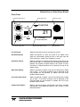
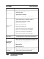
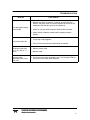
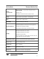
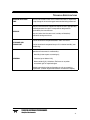
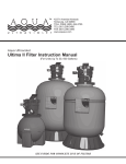
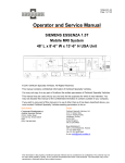
TED '
PORTABLE OXYGEN MONITOR
INSTRUCTION MANUAL
TYPE B EQUIPMENT: Equipment providing a particular degree of protection against electric shock, particularly regarding—
•
allowable LEAKAGE CURRENT
•
Reliability of the protective earth connection
(if present).
P/N TM0021
04/03/00
ECO # 00-0086
TELEDYNE ELECTRONIC TECHNOLOGIES
Analytical Instruments
i
COPYRIGHT © 1996
TELEDYNE ELECTRONIC TECHNOLOGIES – ANALYTICAL INSTRUMENTS
All Rights Reserved
No part of this manual may be reproduced, transmitted, transcribed, stored in a
retrieval system, or translated into any other language or computer language in
whole or in part, in any form or by any means, whether it be electronic,
mechanical, manual, or otherwise, without the prior written consent of Teledyne
Electronic Technologies Analytical Instruments, 16830 Chestnut Street, City of
Industry, CA 91749-1580
Phone (626) 934-1500
FAX (626) 961-2538
Technical Support: (626) 934-1673
TWX (910) 584-1887 TDYANLY COID
or your local representative.
WARRANTY STATEMENT
The electronic control and display components of the TED 191 Portable Oxygen
Monitor are warranted against defective workmanship and materials for 24
months from date of shipment from Teledyne.
The class T-7 Micro-Fuel Cell is warranted for one year from the date of shipment
from Teledyne.
The liability of Teledyne, if any, shall be limited solely to the replacement and
repair of the goods, and shall not include shipping costs or other incidental
damages as defined in Section 2-715 of the U.S Uniform Commercial Code.
This warranty is null and void if any goods are subjected to misuse, negligence,
accident or repairs other than those performed by Teledyne or an authorized
service center.
Caution:
Federal Law restricts this device to sale by or on the order of a
physician.
TELEDYNE ELECTRONIC TECHNOLOGIES
Analytical Instruments
2
TABLE OF CONTENTS
SECTION TOPIC
PAGE NUMBER
INTRODUCTION
4
APPLICATIONS
5
DESCRIPTIONS OF FUNCTIONAL ZONES:
FRONT PANEL
REAR PANEL
6
7
OPERATIONS:
1.
1.1
1.2
1.3
1.4
1.5
1.6
SET-UP
INSTALL THE BATTERIES
INSTALL THE SENSOR
CALIBRATE THE INSTRUMENT
NORMAL OPERATION
SET THE ALARMS
8
9
10
11
12
13
2.
ANAESTHETIC AGENTS
14
3.
CLEANING
15
4.
DO’S AND DON’T’S
16
5.
ROUTINE MAINTENANCE
6.
TROUBLESHOOTING
18
7.
TECHNICAL SPECIFICATIONS
20
8.
EFFECT OF PRESSURE
22
9.
EFFECT OF HUMIDITY
23
10.
EFFECT OF TEMPERATURE
24
11.
DISCREPANCY IN READING
25
12.
REPAIR SERVICE
26
SENSOR CELL REPLACEMENT LOG
27
TECHNICAL SERVICE LOG
28
GENERAL NOTES
29
SPARE PARTS LIST
30
.
17
TELEDYNE ELECTRONIC TECHNOLOGIES
Analytical Instruments
3
INTRODUCTION
The TED 191 Portable Oxygen Monitor is an easy-to-use, portable instrument that provides fast
and accurate oxygen monitoring and audio-visual alarm capability. The TED 191 is designed to
monitor concentrations of up to 100% oxygen in medical gas mixtures.
The TED 191 Portable Oxygen Monitor is designed and manufactured in accordance with strict
performance and quality protocols and subject to ISO 9002 Quality System protocols. When used
correctly, this instrument will provide you with many years of trouble free service.
The TED 191 Portable Oxygen Monitor is a compact, self-contained unit, which is battery powered
by four (4) dry cell batteries (size AA/penlight).
TELEDYNE ELECTRONIC TECHNOLOGIES
Analytical Instruments
4
APPLICATIONS
The instrument is designed for the measurement of oxygen concentrations in a variety of medical
gas mixtures. It is recommended that the instrument be used only as a secondary measuring
device to verify the concentration of oxygen in gas mixtures prepared using a gas blender or
similar apparatus. The use of this monitor as a primary or only means of preparing gas mixtures is
not advised.
The monitor is capable of verifying oxygen concentrations in gas mixtures used in:
•
•
•
•
Anesthesia
Neonatal Intensive care
Adult Intensive care
Respiratory / Oxygen Therapy
TELEDYNE ELECTRONIC TECHNOLOGIES
Analytical Instruments
5
DESCRIPTION OF FUNCTIONAL ZONES
FRONT PANEL
High Alarm Setting Knob
50
Alarm Mute Button
Calibration Control
60
TELEDYNE
70
40
30
80
HI
90
21
50
X
102
60
70
40
30
80
LO
% OXYGEN
OXYGEN MONITOR
90
21
21
I
O
102
Liquid Crystal Display (LCD)
Low Alarm Setting Knob
On / Off Switch
On / Off Switch
Allows the operator to turn the instrument on and off.
Alarm Mute Switch
Allows the operator to “mute” the sound of the audible alarm
signal for ± 60 seconds. During this time, a red signal lamp will
flash, indicating a “muted” alarm condition is in force.
Calibration Control
Allows the operator to calibrate the instrument to one primary set
point (usually 100%) in accordance with the designated calibration
protocol. This protocol is defined further in this manual and also.
Instructions in abbreviated form can be found on the top of the
monitor casing.
High Alarm Setting
Allows the operator to define a high alarm threshold limit. Range
18% to 102% - if the actual measured value as displayed on the
LCD exceeds this set threshold, an audible and visual alarm
condition will be invoked.
Low alarm setting Knob
Allows the operator to define a low alarm threshold limit. Range
18% to 100% - if the actual measured value as displayed on the
LCD falls below this set threshold, an audible and visual alarm
condition will be invoked.
Liquid Crystal Display
Displays measured oxygen concentration, low battery condition
and provides a visual indication of either a high (+) or low (-) alarm
threshold violation.
TELEDYNE ELECTRONIC TECHNOLOGIES
Analytical Instruments
6
DESCRIPTION OF FUNCTIONAL ZONES
REAR PANEL
Sensor Cable Connector Plug
Battery Drawer
Battery Drawer
The Battery Drawer contains 4 x AA (Penlight) batteries
required to power the instrument.
Sensor Cable Connector Plug
The Oxygen Sensor Connector Cable is plugged into this
“one way” socket.
TELEDYNE ELECTRONIC TECHNOLOGIES
Analytical Instruments
7
SECTION ONE
OPERATIONS
Note : Upon receipt, inspect the entire unit and accompanying accessories for damage or broken
or loose parts. If damaged, do not use. Notify the Shipper, and consult Teledyne
Electronic Technologies Analytical Instruments
1.1 SET-UP
To set-up your TED 191 Portable Oxygen Monitor :
1.1.1 Install the Batteries
See 1.2 below for procedure
1.1.2 Install the Sensor
See 1.3 below for procedure
1.1.3 Calibrate the Instrument
See 1.4 below for procedure
1.1.4 Normal Operation
See 1.5 below for procedure
1.1.5 Set the Alarms
See 1.6 below for procedure
TELEDYNE ELECTRONIC TECHNOLOGIES
Analytical Instruments
8
OPERATIONS
1.2 INSTALLING THE BATTERIES
Withdraw the battery drawer from the monitor casing, by grasping the side lugs located on
either side of the battery drawer, and, firmly pinching them inwards, simultaneously pull the
drawer outwards. When new, this action can be somewhat stiff and difficult to execute. Care
should be taken not to damage either the drawer or the casing of the monitor when
executing this procedure.
Fresh batteries must be inserted into the four battery recepticles located within the battery
drawer assembly. Care should be taken to ensure that the correct battery polarity is
maintained.
Caution :
Improper installation of the batteries may result in heat damage to the
batteries.
Re-insert the battery drawer into the monitor casing, and close.
TELEDYNE ELECTRONIC TECHNOLOGIES
Analytical Instruments
9
OPERATIONS
1.3
INSTALLING THE OXYGEN SENSOR
The T-7 Oxygen Sensor must be installed before the instrument can be used.
Ensure that the monitor is switched off.
Remove the sensor from its protective bag. Inspect the sensor for damage or electrolyte
leakage. If the sensor is damaged obtain a replacement. Do not use the defective sensor as
it may be damaged.
Caution: the sensor electrolyte is caustic. Do not let it come into contact with skin. If it does,
immediately flush the affective area with water. Consult the Emergency First Aid procedures
as set out in the Material Safety Data Sheet for the sensor. Do not attempt to open or repair
the sensor. Leaking or exhausted sensors should be disposed of in accordance with local
regulations. Consult the Material safety Data Sheet supplied with the sensor.
Plug one end of the coiled cable into the telephone jack receptacle on the end of the
sensor. The jack will only fit one way, so if it does not fit, rotate it until it slides in easily.
Plug the other end of the coiled cable into the receptacle located on the right hand side of
the rear panel of the instrument. This jack will only fit one way, so do not force it.
Note :
For sterilization procedures on the Oxygen Cell, see Section 3 on Page 15 below.
Caution :
Do NOT autoclave the oxygen sensor
TELEDYNE ELECTRONIC TECHNOLOGIES
Analytical Instruments
10
OPERATIONS
1.4
CALIBRATE THE INSTRUMENT
Calibration should be effected at least once per shift, and always prior to the use of the
instrument.
Note:
Never expose the sensor to varying temperatures while calibrating (i.e never hold
the sensor in your hand)
Ensure that the instrument is switched on, and that the oxygen sensor is connected to the
instrument via the coiled cable. Expose the sensor tip to pure (100%) free flowing oxygen (a
flow rate of approximately 6 to 8 litres per minute is recommended).
Tip:
For best calibration results, use a T-adapter and flow diverter within a flow circuit,
with the flow diverter attached to the sensor, allowing pure dry oxygen to flow past
the sensor assembly.
Allow the displayed value to stabilize.
Pull out the Calibration Control Knob and rotate until the displayed value is stable at 100%.
At this point, push the Calibration Control Knob back into its locked position.
Turn off oxygen supply and place sensor in ambient air. Remove the flow diverter from the
Sensor, if one was used during the calibration process, Observe that the displayed value
falls to 21% (±2%). Calibration has been successful.
In the event that the displayed value does not reflect 21% (±2%), initiate a re-calibration
(following the steps outlined above).
In the event that calibration is once more unsuccessful, check that the purity of the
calibration gas being used is valid. If the quality of the oxygen being used in the calibration
process is acceptable, and calibration is still impossible, replace the oxygen sensing cell.
Note:
The calibration process should always be executed in dry, non-humidified
oxygen. Water vapour dilutes the oxygen concentration which can produce
errors in the calibration. The accuracy of the instrument is only as good as the
quality of the calibration process.
Note:
It is not uncommon for the ambient air in hospital wards to be as high as 23%.
If the unit fails the 21% calibration reading move the instrument to a location
where oxygen contamination is unlikely.
TELEDYNE ELECTRONIC TECHNOLOGIES
Analytical Instruments
11
OPERATIONS
1.5
NORMAL OPERATION
Switch the instrument on using the On–Off Switch.
Validate the calibration of the instrument by exposing the oxygen sensor to room air, and
verifying that the display on the instrument reads 100% (± 2 %). A further check can be
carried out by exposing the sensor to a stream of 21% oxygen, and verifying that the display
on the instrument reads 100% (± 2 %).
Should this validation procedure indicate that the instrument is out of calibration, follow the
calibration procedures set out in 1.4 above.
Once the calibration of the instrument has been verified, place the sensor tip within the
stream of gas (e.g. breathing circuits) or the localised environment (e.g. incubators or
oxygen tents) that requires to be monitored.
It is highly recommended that a flow diverter be used when monitoring a dynamic gas
stream. This will prevent sample stagnation, and create a vortex effect that will facilitate a
more accurate continuous assessment of the gas stream being monitored. The flow
diverter should be plugged into a T-adapter, which must be located in line.
Note:
Check the breathing circuit for leaks. Ensure that the circuit downstream of the
sensor does not produce any back-pressure or restrictions of the gas flow, or
errors in the readings will result.
When using the instrument in a static environment, such as in an incubator, the flow diverter
should be removed so that it does not interfere with the rapid exchange of gases through
the gas permeable membrane of the sensor cell. When it is necessary to thread the cable
through a small hole in order to gain access to the inside of the chamber, the instrument
should be switched off, the cable should be disconnected at the sensor, threaded through
the hole, and reconnected inside the chamber (see1.3 above), before commencing as
described above.
Note:
Failure to remove the flow diverter will result in the marked slowing of the
sensor response time.
The instrument will display the measured oxygen concentration. The high and low alarms
should be set as detailed in 1.6 below.
When using the instrument in the presence of anaesthetic agents, it is possible for the
measured value to reflect a fall. The magnitude of this fall is related to the level of oxygen
concentration and the duration of the exposure to the anaesthetic agent. See 1.7 below for
further details.
TELEDYNE ELECTRONIC TECHNOLOGIES
Analytical Instruments
12
OPERATIONS
SET THE ALARMS
The lines indicating the 100% graduations around the High and Low Alarm Settings Knobs
are only intended as guides, and not as precise settings.
Once the desired oxygen concentration has been set, bring the high alarm setting down, by
turning the High Alarm Setting Knob anti-clockwise, until the alarm is triggered, and then
take the high alarm setting up by approximately 5%. Bring the low alarm setting up, by
turning the Low Alarm Setting Knob clockwise, until the alarm is triggered, then take the
setting down by approximately 5%. These settings will create a “window” of approximately
10%, within which the set oxygen concentration will now be measured. This window can be
increased or decreased, according to the users requirements. Any deviation from this set
window will trigger the alarm.
The graph alarm is accurate at 100% and within ±8% at 21%, and the low alarm is most
accurate at 21%, and within ±8% at 100%. This is depicted in the graph below.
Oxygen Monitor
Alarm Setting Tolerances
100
80
Alarm Setting
1.6
Alarm Point
60
Low Alarm
High Alarm
40
20
20
40
60
80
100
Oxygen Concentration Reading
The instrument will alarm at any oxygen concentration below 18%.
In the event of a violation of the pre-set alarm limits, the instrument will provide both an
audible and a visual alarm signal. Under these conditions, it is possible to “mute” or
temporarily silence the audible alarm tone for about 60 seconds to allow corrective action to
be taken. If the condition is not rectified within this time, then the audible alarm tone will be
automatically reinstated. Audible alarm signals are tonally matched to the type of threshold
violations i.e. low alarm violations are signalled via a lower pitched audible signal, while
high alarm violations are signalled via a higher pitched audible signal.
TELEDYNE ELECTRONIC TECHNOLOGIES
Analytical Instruments
13
SECTION TWO
2.
ANAESTHETIC AGENTS
ANAESTHETIC AGENTS
The anaesthetic agents listed in the following table (Halothane, Enflurane, Isoflurane Sevoflurane,
and Desflurane) were vaporised into a stream of 30%oxygen / 70% nitrous oxide. The resultant
drops in displayed oxygen concentration after a 2 hour exposure period were observed.
Exposurers in excess of 2 hours will provide marginally greater errors. The errors listed are typical
for all gas permeable membrane oxygen sensors.
Exposure of the sensor to gas, free from any anaesthetic contamination, for a period of equal or
greater than the exposure period, will eliminate the measurement error in most instances.
Gas or Vapor Level
(Balance : Mixture of 30% O2 / 70% N2O, except where noted)
Gas or Vapor
Helium
Nitrous Oxide
Carbon Dioxide
Halothane
Enflurane
Isoflurane
Sevoflurane
Desflurane
Test Level
50%, balance O2
80%, balance O2
10%, balance O2
4%
5%
5%
5%
15%
Oxygen Reading Error
0%
0%
0%
*
< -1.5% O2
*
< -1.5% O2
*
< -1.5% O2
*
< -1.5% O2
*
< -1.5% O2
*
Errors are approximate and may vary based on exposure times and concentrations. These
performances meet or exceed the requirements of ISO 7767: 1997 (E)
Caution:
The TED 191 Portable Oxygen Monitor should not be used in the presence of
flammable anaesthetics such as diethal ether or cyclpropane.
The T-7 oxygen sensor should not be left in nitrous oxide mixtures any longer than absolutely
necessary. After exposure to nitrous oxide mixtures, the sensor should be left in 100% oxygen
overnight (e.g. left in a breathing circuit that has been flushed with pure oxygen). If the oxygen
reading continues to drop after each use in nitrous oxide, the sensor should be removed from
service. If the sensor can no longer be calibrated, or if there is any sign of electrolyte leakage, the
sensor should be disposed of in accordance with local regulations and the specific guidelines as
given in the Material Safety Data Sheet of the sensor.
TELEDYNE ELECTRONIC TECHNOLOGIES
Analytical Instruments
14
SECTION THREE
CLEANING AND STERILISATION
3.1 CLEANING THE TED 191 PORTABLE OXYGEN MONITOR
The instrument itself should be cleaned using a damp cloth. In the event of an excessive
build-up of dirt, a mild alcohol solution (isopropyl) may be used to wipe over the instrument,
which should be allowed to air-dry afterwards. In extreme cases, the monitor casing may be
cleaned using a mild detergent.
Note:
3.2
The Accurox Oxygen monitor cannot be liquid sterilised or autoclaved –
irreparable damage may result.
STERILISING THE T-7 OXYGEN SENSOR AND CONNECTING CABLE
The T-7 oxygen sensors and connecting cables used on the instrument may be gas
sterilised using low temperature ethylene oxide. A vacuum must not be drawn on the
sensor during the sterilisation process.
TELEDYNE ELECTRONIC TECHNOLOGIES
Analytical Instruments
15
SECTION FOUR
DO’S AND DON’TS
DO’S
; Read the Operators Manual thoroughly before using the instrument.
; Calibrate once per shift, and prior to each and every use.
; Check the high and low alarm threshold settings prior to use.
; Replace the batteries immediately when required.
; Keep the instrument, cable and sensor dry at all times.
; Re-calibrate after changing the sensor or batteries.
; Visually inspect the whole instrument prior to use.
; Check the integrity of all cable connections routinely.
; Remove and carefully store the “flow diverter” when using the instrument in “static”
environments such as incubators, oxygen hoods etc.
; Perform an alarm functionality test prior to each use.
; Remove batteries if the instrument is not to be used for a month plus
DON’TS
: Use the Accurox Oxygen Monitor if you suspect any malfunction.
: Use the monitor in the presence of flammable anaesthetics.
: Autoclave the instrument and/or the sensor.
: Submerge the instrument and/or sensor in water or any other liquid.
: Expose instrument to other equipment with high levels of RFI emission.
: Place the instrument itself in a water vapour saturated environment.
: Expose the LCD to excessive direct sunlight
: Dispose of the sensor cell in fire, or place in an incinerator.
TELEDYNE ELECTRONIC TECHNOLOGIES
Analytical Instruments
16
SECTION FIVE
ROUTINE MAINTENANCE
5.1 ROUTINE VISUAL INSPECTION
Always inspect the instrument prior to use for obvious damage or for parts or components
missing. Make a point of checking the oxygen sensor cell for signs of electrolyte leakage,
water condensation on the sensing surface. Also check the integrity of the cable and all
cable connections.
5.2 CHANGING BATTERIES
From time to time the 4 x AA (penlight) dry cell batteries that power the instrument will
require replacement. This requirement will be indicated via a "LO BAT" alarm message
located in the top left hand corner of the LCD display. It is also possible, if the instrument
has not been used for sometime, that the batteries will be depleted to the extent that the
instrument will not power up when switched on. In both instances, the batteries must be
replaced.
To change the batteries, follow the procedures set out in 1.2 above.
Initiate a calibration once the new batteries are installed prior to using the instrument.
5.3 CHANGING THE OXYGEN SENSOR CELL
From time-to-time the oxygen sensor cell, being a consumptive electro-chemical device, will
require replacement. This requirement will be indicated via an inability to achieve calibration
i.e the range provided by the Calibration Control Knob will not be sufficient to achieve the
setting of 100% on the LCD display when exposing the sensor tip to 100% pure oxygen.
To change the oxygen sensor, follow the procedures set out in 1.3 above.
Initiate a calibration once the new sensor has been installed prior to using the instrument.
A Sensor Cell Replacement Log has been provided for the reference of the users, and is
located at the back of this Instruction Manual. The details of the replacement sensor should
be entered into this log at the time of changing.
TELEDYNE ELECTRONIC TECHNOLOGIES
Analytical Instruments
17
SECTION SIX
TROUBLESHOOTING
SYMPTOM
CURE / REMARK
1) Check battery drawer is properly located.
No numeric display on
the LCD when powered
on
2) Check battery polarity .
3) Check batteries for replacement
4) External power : check polarity and voltage of supply;
: check if functional on batteries.
1) Check calibration process (as described in section 1.4).
2) Check flow rate of calibrating gas (6 – 8 lpm)
3) Check sensor cell connection.
4) Check sensor cable connection.
Inability to achieve
calibration
5) Check quality of calibration gas.
6) Check that the calibration gas is dry (not humidified).
7) Wait for 1 or 2 minutes, then attempt a re-calibration.
8) Check sensor cell for damage or electrolyte leaks.
9) Return monitor to authorized service agent for repair.
Constant non-mutable
alarm condition
Drift is displayed
readings whilst
calibrating or
immediately thereafter
1) Check high and low alarm settings for possible “crossed” settings
i.e. high threshold value is set lower than low threshold value.
1) Do not hold the sensor whilst calibrating, as the warmth from your
hand may cause the ambient temperature compensation circuit to
activate, resulting in unstable displayed values.
2) Try calibrating a known “good” sensor.
3) Repeat calibration.
4) Replace the sensor cell.
There is no reaction to
changes in oxygen
concentration
1) Remove the sensor tip from the T-adaptor, unscrew the “flow
diverter” and gently swab any excess moisture off the sensor cell
membrane, then flow dry gas over the membrane.
TELEDYNE ELECTRONIC TECHNOLOGIES
Analytical Instruments
18
TROUBLESHOOTING
SYMPTOM
CURE / REMARK
1) Remove the sensor tip from the T-adaptor, unscrew the “flow
diverter” and gently swab any excess moisture off the sensor cell
membrane, then flow dry gas over the membrane.
The displayed readings
are unstable
2) Check for a source of RFI emission. Relocate the instrument.
3) Check that the calibration control knob is properly locked in
position.
1) The sensor is not plugged in.
Instrument reads “00”
2) There is bad sensor/cable or cable/monitor connection.
Displayed value drifts
by 2 – 3% over 3 – 4
hours
Alarm continuously
activates when
displayed value is less
than 18%
1) Replace sensor cable.
2) Replace cable.
1) The minimum low alarm threshold is 18%. The Teledyne TED 191
will always alarm under these conditions.
TELEDYNE ELECTRONIC TECHNOLOGIES
Analytical Instruments
19
SECTION SEVEN
TECHNICAL SPECIFICATIONS
Complies to IEC 601 – Safety of Medical Equipment Internally
powered equipment
SAFETY
CLASSIFICATION
Drip proof – IPX 1
Not suitable for used with flammable anaesthetic mixture
POWER
Internal : DC 6V, 4 dry cell batteries – size AA/penlight
MASS
525 grams (with T-7 oxygen sensor)
DIMENSIONS
59mm (H) x 152mm (W) x 115mm (D)
Approximately 900 hours of continuous non-alarming operation
BATTERY DURATION
Low battery status indication is provided
Replace batteries within 48 hours of low battery indication
High oxygen concentration (18% to 102%)
Low oxygen concentration (18% to 100%)
ALARMS
Low battery (visual alarm only)
Most alarm conditions are signalled audibly and visually, with a 60
second audible alarm mute facility provided
MEASUREMENT RANGE
0 to 100% of localised environmental oxygen concentration
DISPLAY TYPE
Liquid Crystal Display (LCD)
SENSOR TYPE
Class T-7 (Galvanic)
ACCURACY
Approximately 2% linear
SENSOR LIFE
Approximately 12 months in most applications
TELEDYNE ELECTRONIC TECHNOLOGIES
Analytical Instruments
20
TECHNICAL SPECIFICATIONS
SENSOR RESPONSE
TIME
Less than 6 seconds to 90% of final measured value in response to
a step change in the actual oxygen concentration being measured.
Technical manual will be supplied on request to user’s appropriately
qualified personnel for repair of components designated as
repairable by the manufacturer.
SERVICE
No parts (other than the sensor cell, and dry cell batteries)
deteriorate during normal use.
Can be stored and transported between -30°C and +50°C
STORAGE AND
TRANSPORT
Can be stored and transported at up to 75% relative humidity (noncondensing)
Operation of instrument is unaffected by :
Humidity (water vapour saturated gas);
GENERAL
Pressure (up to 100cm H2O);
Nitrous oxide (N2O), Halothane, Enflurane or any other
anaesthetic gas or vaporised agent.
Multiple mounting bracket configurations to suit any mounting
requirement. (Custom engineered solutions available on request).
TELEDYNE ELECTRONIC TECHNOLOGIES
Analytical Instruments
21
SECTION EIGHT
EFFECT OF PRESSURE
Virtually all gas sensors and analysers measure the partial pressure, not the percentage, of the
gas that they sense. The only time that these instruments can accurately read percentages is
when the total pressure does not vary over time between calibration and use. This is why it is
important to calibrate the TED 191 Portable Oxygen Monitor at regular intervals.
It is recommended that the instrument be calibrated prior to each use or every 8 hours.
When the sensor is connected to a ventilator circuit, the alternating "breathing" pressure cycles
generated by the ventilator will be sensed as an increase in the oxygen percentage (especially if
the sensor is fast enough to sense the changes). In reality, the percentage of oxygen is not
changing; it is the total pressure that is increasing, producing a corresponding increase in the
partial pressure of oxygen. A hundred-centimeter water pressure pulse will produce a .11
atmosphere, or an 11% increase in the total and therefore partial pressure of oxygen. Assuming
that the sensor is fast enough to track this pressure pulse, an unpressurised reading of 50%
oxygen will increase to 55.3% if the sensor is subjected to a pressure cycle of 100cm H2O. The
reading will rise proportionally less for smaller pressures.
TELEDYNE ELECTRONIC TECHNOLOGIES
Analytical Instruments
22
SECTION NINE
HUMIDITY
EFFECT
OF
Humidity does not directly affect the accuracy of the sensor's measurement. However, when a
nebuliser or other device is used to increase moisture levels in gas mixtures, the moisture actually
dilutes the mixture. This dilution effect decreases the oxygen concentration.
For example, if an 80% oxygen gas mixture is humidified to saturation at room temperature, the
resulting gas mixture will contain only 77.5% oxygen. Your TED 191 Portable Oxygen Monitor
accurately measures decreases in the oxygen concentration due to the dilution effects of moisture
added to gas mixtures.
As with all oxygen sensors, excessive condensation on the sensing surface will block the diffusion
of oxygen to the sensor, rendering it inoperative. It is recommended that the sensor be installed on
the dry side of the breathing circuit at all times.
Water condensate on the exposed cable contacts at the rear of the sensor may affect the oxygen
reading and should be removed by shaking out the condensed water and allowing the sensor to
air dry.
TELEDYNE ELECTRONIC TECHNOLOGIES
Analytical Instruments
23
SECTION TEN
TEMPERATURE
EFFECT
OF
The Teledyne Electronic Technologies Analytical Intruments sensors adjust for ambient temperature
changes in the range of 0 - 40ºC (32 - 106ºF). Since the thermistor that compensates for these
changes is located in the rear of the sensor assembly, it is important that gas mixtures, flowing
over the front of the sensor, be at room temperature. Reading errors may occur if hot gases from a
heated humidifier are directed past a sensor teed into a breathing circuit.
A small thermal tracking error may be encountered in applications where the entire sensor
assembly is placed in the gas mixture to be analysed (e.g incubators). No adjustments should be
made during this period (about 1 to 2 hours), since this error will be eliminated when both the
thermistor and sensing electrode have had sufficient time to come to thermal equilibrium.
TELEDYNE ELECTRONIC TECHNOLOGIES
Analytical Instruments
24
SECTION ELEVEN
READINGS
DISCREPANCY
IN
The TED 191 is intended to be used as a secondary oxygen monitor, meaning that it is intended
to verify the accuracy of and check the oxygen concentration leaving another oxygen mixing
device or primary life support system (i.e a blender or anaesthesia machine). Whenever there is a
significant difference in the oxygen readings between the primary and secondary monitors, the
discrepancy must be resolved immediately. The information obtained from the TED 191 should
never be used to make adjustments to the primary life-support system, but should only be used as
an indication that the primary device may require service and/or calibration.
The "LO BAT" message immediately tells you if the batteries need replacing. The TED 191 should
momentarily be removed from the application area and the batteries replaced. If the TED 191 can
be calibrated, the unit can be assumed to be in good working order and capable of providing
readings to specification. If after re-installing the TED 191, the discrepancy in oxygen readings
persists, the problem is most likely elsewhere (i.e flow blockage, primary device error, etc.).
Further investigation should be made until the discrepancy in readings is resolved.
If it is found that replacing the sensor and/or batteries does not give proper calibration results, the
troubleshooting section of this manual should be consulted.
TELEDYNE ELECTRONIC TECHNOLOGIES
Analytical Instruments
25
SECTION TWELVE
SERVICE
REPAIR
In the event that your TED 191 Portable Oxygen Monitor requires service, the following steps will
help to ensure that the repair request is processed promptly :
Contact your authorised Teledyne Electronic Technologies Analytical Instruments distributor
or factory for return instructions. Do not ship your monitor without first obtaining authorisation.
Include a copy of the sales invoice or other proof of purchase date. Warranty service may be
denied if no proof of purchase is included.
It is your responsibility to pay shipping charges to Teledyne Analytical Instruments. If the unit is
under warranty, the serviced or replaced monitor will be returned to you postage prepaid.
Monitors and sensors damaged by accident or misuse are not covered by the warranty. In
these cases, service charges will be based on time and materials.
TELEDYNE ELECTRONIC TECHNOLOGIES
Analytical Instruments
26
SENSOR CELL
REPLACEMENT LOG
DATE
WARRANTY?
SERIAL NUMBER
N/A
REMARKS
MANUFACTURED
TELEDYNE ELECTRONIC TECHNOLOGIES
Analytical Instruments
27
TECHNICAL SERVICE LOG
DATE
WARRANTY?
DETAILS
REMARKS
TELEDYNE ELECTRONIC TECHNOLOGIES
Analytical Instruments
28
GENERAL NOTES
TELEDYNE ELECTRONIC TECHNOLOGIES
Analytical Instruments
29
SPARE PARTS
LIST
SPARE PARTS
PART NUMBER
A51327
C885
A268
DESCRIPTION
Micro-Fuel Cell T-7 with flow diverter P/N A50057
Cable assembly
Tee adapter (22mm)
OPTIONAL ACCESSORIES
PART NUMBER
B34102
C53790
A284
A274
A283
DESCRIPTION
Mounting Clamp
Calibration Assembly
Universal adapter set for paediatric circuits (15mm)
Tee adapter, autoclaveable
Tee adapter, metal
A minimum charge of US$20.00 is applicable to spare parts orders.
Important :
Orders for spare parts should include the model number, serial number,
and range of the analyzer for which the parts are intended.
Orders should be sent to :
Teledyne Electronic Technologies
Analytical Instruments
16830 Chestnut Street
City of Industry, CA 91749-1580
Phone :
(626) 934-1500
Fax :
(626) 961-2538
TWX :
(910) 584-1887 TDYANLY COID
Web:
www.teledyne-ai.com
or your local representative
TELEDYNE ELECTRONIC TECHNOLOGIES
Analytical Instruments
30