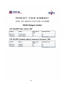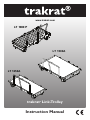
1
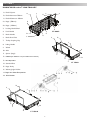
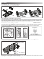
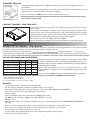
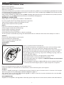
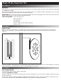
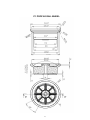
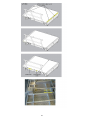
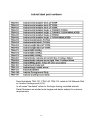
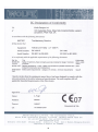
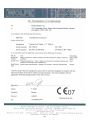
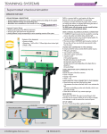
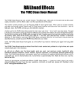
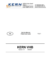
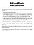
www.trakrat.com
LT 1000 P
LT 1500A
LT 1250A
®
trakrat Link-Trolley
Instruction Manual
Thank you for purchasing a trakrat® Link-Trolley
Before using this equipment and to avoid personal injury, carefully read and understand these instructions. If
there is anything you do not understand, DO NOT use this equipment, contact your supplier for advice.
Regular inspection, servicing and periodic maintenance will ensure many years of trouble free operation.
CONTENTS
trakrat® Link-Trolley
SECTION 1
SECTION 2
SECTION 3
SECTION 4
SECTION 5
SECTION 6
SECTION 7
SECTION 8
SECTION 9
PAGE
Introduction / Disclaimers
General Safety / Risk Assessment
Know your trakrat® Link-Trolley
Assembly Instructions
Operating instructions
Cleaning and general care
Technical data
Warranty
Stopping Distance Table
1
2–3
4
5
6
8
11
11
12
Bogie Brake Inspection Test
SECTION 10
SECTION 11
SECTION 12
SECTION 13
SECTION 14
SECTION 15
General
Inspection
Test Procedure
Brake Pad / Wheel / Disc Replacement Procedure
Disc and Wheel Removal
Brake Pad Removal
SECTION 16
SECTION 17
Label Information
Certification
9
10
25 - 31
trakrat® Link-Trolley
INTRODUCTION
DESCRIPTION
The trakrat® Link-Trolley is a portable link trolley for use on rail infrastructure.
Polymer Link Trolley,TR 1000 P : Constructed from Polypropylene and aluminium to give a combination of strength with minimum
weight.
NB: Please note that local practice may limit the SWL capacity to 1000Kg
Model Number
Description
Capacity (kgs) Deck (mm)
LT 1000 P
Link Trolley 1000 Plastic
1000
800 x 1750
LT 1250 A
Link Trolley 1250 Aluminium
1250
750 x 1800
LT 1250 A - I
Link Trolley 1250 Aluminium - Insulated
1250
750 x 1800
LT 1250 W
Link Trolley 1250 Wood
1250
750 x 1800
LT 1250 W - I
Link Trolley 1250 Wood - Insulated
1250
750 x 1800
LT 1500 A
Link Trolley 1500 Aluminium
1500
1150 x 1800
LT 1500 A - I
Link Trolley 1500 Aluminium - Insulated
1500
1150 x 1800
LT 1500 W
Link Trolley 1500 Wood
1500
1150 x 1800
LT 1500 W - I
Link Trolley 1500 Wood - Insulated
1500
1150 x 1800
1
The trakrat® Link-Trolley comprises of a deck and two bogies. Both bog i es are detachable to enable the users to transport
the trakrat® Link-Trolley manually over reasonable distances where access by vehicular transport is not an option
The trakrat® Link-Trolley is fitted with a unique disc brake system which increases braking efficiency and reduces wheel damage
associated with traditional block brakes.
An additional version is available with wheels isolated from the main bogie for use on underground rail systems.
DISCLAIMERS
Due care has been taken in the publication of this User /Operator Manual, but it is intended as a guide only.
The information and instructions included in this manual are provided to help you get the best possible service from your
trakrat® Link-Trolley.
Users are reminded of their individual responsibility to ensure health and safety at work and their duty under current Health
and Safety Legislation.
No warranties are implied or offered in relation to this manual, its content or use and Wolfe Designs Ltd. accept no liability
whether actual or consequential arising from its use, or that its use alone is sufficient to ensure the safety of those so engaged.
Your statutory rights remain unaffected.
Wolfe Designs Ltd operate a policy of constant improvement and reserve the right to change specifications without notice.
Wolfe Designs Ltd. reserve the right to alter/delete or make additions to this manual without notice at any time as is deemed
necessary.
SECTION 2
SAFETY
To ensure that the trakrat® Link-Trolley is used safely and responsibly, we strongly recommend that this manual is read by all
users prior to operating the trakrat® Link-Trolley, and that the recommendations are followed at all times.
Make sure you are aware of all safety requirements and that this equipment is suitable for the task you wish to undertake.
This equipment must not be moved, set up, used or dismantled by persons who are under the influence of alcohol or drugs.
Do not use this equipment if you are tired or unwell.
Test brakes in accordance with brake test procedure as published.
Always read and follow the safety information found on the details fitted to the trakrat® Link-Trolley.
Be aware of trap hazard between 2 linked trolleys.
Use red indicator lights where required.
Do not overload the platform beyond the stated weight loading for the model you have and ensure that you secure any load
adequately.
Wear the correct Personal Protective Equipment for the task you are performing.
Do not wear loose jewellery or clothing that may get in the way or become trapped in the mechanism.
Inform everyone in the work area of what you are doing.
Carefully inspect the trakrat® Link-Trolley during and after assembly and before each work session, if there is any doubt about
its condition, DO NOT USE IT.
A competent person should remain close by whenever the equipment is being used, in case of an emergency.
It is the responsibility of all user’s to carry out a full risk assessment and ensure that a safe working environment is created and
secured with safe working practices before using the trakrat® Link-Trolley.
EMERGENCY OFF-TRACKING
To off-track in an emergency requires two people. Each person should grasp the lifting
handle from one side of the unit and raise so that the bogie on the other side is used
to pivot the trakrat® on the track.
Your risk assessments must include, but are not limited to:
• Manual Handling
• Safe Working Conditions
• Safe Operation
• Safe and Secure Transportation
The trakrat® Link-Trolleys must only be used by authorised personnel, suitably trained in their use and deployment.
Where needed it is the operator’s responsibility to ensure all necessary Permits/permissions or authorisations are in place
prior to using this equipment on the infrastructure.
2
trakrat® LINK TROLLEY RISK ASSESMENT
Issue 1 Dated: 2007
PURPOSE
This document is intended to provide an assessment of the hazards and risks involved to the user(s) of the trakrat® Link
Trolley.
This document does not replace trakrat® Link Trolley user manual which is required reading for any user(s) whom will
additionally require training to perform the safe deployment and use of this machine in accordance with
BSEN13977:2005(E).
TASK
Deployment / Use of the trakrat® Link Trolley
GENERAL SAFETY
Operatives must be fully trained in all aspects of the trakrat® Link Trolley including:
Assembly/lifting/use/maintenance/personal protection equipment.
Prior to use: Consult the manual
Confirm brake test labels are within date (each bogie has an independant brake test label)
Ensure correct assembly
Note that bogie/trolleys labelled for use on LUL (London Underground) must NOT be used on
Network Rail. Bogie/trolleys labelled Network Rail must NOT be used on LUL London Underground)
HAZARD
RISK
SOLUTION
Incorrect assembly
Personal injury
Check correct assembly
Lifting assembled trolley
Personal injury
LT1500A. Where possible remove bogies
and lift components seperately.
Maneuvering
Personal injury to self or others
Ensure safe and proper access
Dropping
Personal injury to self or others
Overloading / Uneven Loading
Personal injury and damage to the
trolley
Overhanging loads
Injury to self and others plus damage to Exercise caution and never allow
overhanging loads to under hang the
the infrastructure
deck
Brake failure / Runaway
Injury to self and others plus damage to Check and maintain the brakes
infrastructure
Never tie off failsafe braking devices
Tripping
Personal injury
Walk at a proper pace for the prevailing
conditions
Transport / Storage
Personal injury to self or others
Ensure all components are properly
stacked and secured
Minimum 3 man lift or 4 man lift for the
3
Ensure conditions underfoot are viable
and min 3 man lifts , 4 man lift for
LT1500A
Observe load limits
SECTION 3
KNOW YOUR trakrat® LINK-TROLLEY
1a. Deck Polymer
1a
6
1b. Deck Aluminium 750mm
4
5
16
1c. Deck Alluminium 1150mm
16
2a. Bogie (750mm)
15
2b. Bogie (1150mm)
3. Locking Hand Wheel
8
LT 1000 P
4. Push Handle
8
2a
5. Brake Handle
16
9
4
6. Brake Pivot Plate
7.
1b
Trolley Coupling Cap
6
8. Lifting Handle
9. Wheel
8
10. Axle
11. Spacer (Large)
5
12. 19MM Nylon Washers x 2 (On inside of box section)
2a
16
13. M12 Nylok Nut
9
14. Standard Disc
15. Bogie Body
16. Warning Light Holder
17. Bogie Anti Skew Receptacles
18 . M12 Washer
1b
4
6
8
16
2b
5
9
LT 1500 A
4
LT 1250 A
SECTION 4
ASSEMBLING THE trakrat® LINK-TROLLEY
Position the deck upside down on a firm level surface.
Bogie
Bogie
Deck
LT 1250 A
LT 1000 P
LT 1500 A
Check that the ‘brake test date’ label is valid on each bogie.
Position either aluminium bogie onto the deck, with the brake push rod facing inward. Retain the bogie in place by turning the
locking hand wheel clockwise until secure. Ensuring that the anti skew pins on the deck match up to the receptacles on the
bogie, and the bogie sits flush with the deck.
Check that all brakes function.The braked wheel must resist attempts to rotate it with one hand. Repeat for other side.
Roll the deck over until it is standing on its wheels.
Lift the unit onto the track with all wheels correctly positioned ready to use. Lifting will require a minimum of 33 persons,
Insert the push handle into receiving sockets, ensuring it is fully and securely engaged.
or 4 persons for the LT1500A.
Brake Handle
Bogie
Brake Push Rod
Two pins and two recepticles per side
Brake Pilot Plate
Trolley Coupling Plate
Insert the brake pivot handle onto the brake pivot plate and carry out a test to confirm that moving the handle
in the direction of the ARROW label releases both the wheel brakes evenly.
Push
Handle
Receiving
Slot
Dir
ect
io
no
f Tr
ave
l
Brake Pivot
Plate
Note: both push handle and brake pivot handle can be fitted to either end of the deck and should be placed so that the operator
is pushing the unit in the required direction, NOT pulling.
5
WELDERS TROLLEY
The Welders Trolley comprises of LT 1500 A, with the option of a frame that supports a pair of
gas cylinders.
Insert one frame into receiving sockets on one side of the deck and the remaining frame on the
opposite side. ensure both are fully and securely engaged.
Next, connect the two bottle braces to their respective anchor points.
* Gas bottles must be stood vertically against the bottle brace bars, and be strapped / roped securely
via the tie down eyes provided.
LINKING TRAKRAT® LINK-TROLLEYS
You may link a maximum of 2 trakrat® Link-Trolleys but you may not link to any other
make or model.
Place 2 trakrat® Link-Trolleys in tandem on the track, ensuring that the brake release
direction arrows point in the same direction on each unit. Gently bring them together
until the ‘brake pivot plates’ make contact. Slide the ‘pivot connecting cap’ over the two
‘brake pivot plates’ and double check that they are locked together.
Note that you can link an LT 1250 A with an LT 1500 A.
Activate the brake pivot handle and ensure that all brakes are releasing properly.
SECTION 5
OPERATING THE TRAKRAT® LINK-TROLLEY
The trakrat® Link-Trolley is fitted with two disc brakes, one either side, which remain engaged under normal operation.When
moving the trakrat® Link-Trolley, the brake mechanism must be manually released.
To release the brakes, move the brake lever in the direction of the ARROW (Label) and hold in position. As soon as you
release the lever, the brakes will re-engage. Should the brakes fail to re-engage, the trakrat® Link-Trolley must be removed from
service immediately. Note the brake lever only moves in the direction of the arrow. Align direction arrows when linking trolleys
IN USE CAUTIONS AND LIMITATIONS
Be aware at all times of conditions underfoot; never walk on the railhead
or sleepers. Conditions underfoot will change immediately if wet or icy.
Up to 1 in 250
3
2
1
Gradients, load, ice and wet conditions will all affect the braking distances
1 in 250 to 1 in 150
3
2
1
and braking effort required.
Always work with sufficient personnel to perform the task at hand,
1 in 150 to 1 in 70
(4)
3
1
working within the guidelines for manual handling and operation of this
1 in 70 to 1 in 50
(5)
(4)
2
equipment.
1 in 50 to 1 in 30*
(5)
(4)
2
You must observe 2000kg maximum load pushable by three operatives.
Number of persons required to push a loaded trolley as indicated in CoP0018 Code of Practice.
LOAD GRADIANT 1500kg 1000kg 500kg
* Where authorised by local instructions
( ) Theoretical figures, not recommended.
It is recommended that no more than 3 men push a trolley.
DO NOT
•
•
•
•
•
•
•
•
•
•
•
•
Tie off, mechanically or otherwise the braking handle.
Use the trolley if the brake test labels are either missing or out of date.
Link trakrat® Link-Trolley with other manufacturer’s link trolleys;THEY ARE NOT COMPATIBLE.
Tow, ride on, motorise or exceed walking pace with trolleys.
Stand on trolley.
Overload. Example: where the maximum load = 1000 kg per trolley.
(eg. 2000 kg over 2 trolleys = 1000 kg each NOT 1500 kg on no.1 and
500 kg on no. 2).
Place hot items above 65°C (crucibles, welding torches etc.) onto Polypropylene deck. PERMANENT DAMAGE WILL
OCCUR.
Allow the load to under hang the deck, it may impact the brake mechanism or the infrastructure.
Drag items over the edge of the deck.You must only lift all items and place on to the deck.
Use the Trolley near live DC third rail or fourth rail.
Use the Trolley with insulated wheels where live overhead AC power lines are present.
Link more than 2 trolleys together.
6
SECTION 6
CLEANING AND GENERAL CARE
Observe local regulations.
Operate within Manual Handling Regulations.
Adherence to guidelines.
All maintenance/inspection procedures must be carried out within the guidelines set out in Rail Industry Standards for Portable
and Transportable Plant Used for Infrastructure Work as well as those criteria mandated by CoP0018, Code of Practice for Rail
mounted Manually propelled Equipment.
Axles, wheels and brakes are defined under CoP0018 as Railway Safety Critical and must be maintained in accordance with the
guidelines laid out in CoP0018, Maintenance Elements of Small Plant and Equipment.
GENERAL GUIDELINES
Always adhere to the maintenance schedule as detailed below.
Use only original trakrat® Link-Trolley replacement components.
Only trained, competent staff should complete all work.
Re-cycle used components where possible.
DAILY…
Inspect all components for damage or abnormal wear.
Check integrity of deck/sub frame fastenings.
Check integrity of all bogie fastenings
Check security of axle retaining pins.
Check Maintenance Brake Test Label is in date for each bogie.
Test the operation of all brakes by turning each braked wheel with one hand, the wheel must resist attempts to rotate it.
WEEKLY…
Carry out the daily inspections as above plus:
Inspect all wheels for wear/damage.
Operate and inspect brake linkage tubes.
Check legibility of all labels.
QUARTERLY…
BRAKES
Perform a complete maintenance brake test:
Refer to brake test/inspection and replacement section of the workshop manual.
Inspect all linkages, ensure they are free from damage and operate easily.
Remove all brake pads, inspect for wear and contamination, clean and replace as
required. Pads must be replaced if the brake material gap is less than 1mm thick.
Clean and lightly grease all moving components including all springs whilst reassembling the brake callipers.
Re-fasten all fastenings and test to the appropriate torque settings.
Re-adjust brake levers to remove any play from the system.
Re test using torque brake test, complete the "Maintenance Brake Test Record Sheet"
Conduct practical brake test.
Minimum acceptable torque figure of 90Nm (65lbs ft) must be achieved. If the brakes
do not achieve the minimum figure, replace or adjust components as required.
BEARINGS/AXLES
Examine all wheel bearings for play/noise and replace if worn.
Check the end float on each axle does not exceed 3mm, re-shim with new spacer sets if required.
WHEELS
Conduct a detailed examination of the Aluminium wheels. Check for signs of excessive wear or distortion and compare
dimensions against the P1 profile guage, refer also to diagram on page 16.
If the wheel is worn to the limits indicated on the guage or is likely to reach the max wear limit before the next scheduled
inspection the wheel must be replaced.
UV DEGRADATION
All plastics are susceptible to UV degradation. Check all polymer components for stress fractures, hairline cracks and brittleness.
7
C
CODE NO.
8
SECTION 7
TECHNICAL DATA
LT 1000P
LT1250A
LT1500A
Overall Weight
80 Kilos
76 Kilos
97 Kilos
Deck
40Kg
36Kg
49Kg
20Kg
20Kg
24Kg
Bogie Each
Centre Of Mass
Central
Central
Central
SWL
1000Kg
1250Kg
1500Kg
Length
800mm
750mm
1150mm
Width
1750mm
1800mm
1800mm
Platform Height From Rail Crown
370mm
330mm
330mm
Overall Height Including Push Rail
1000mm
1000mm
1000mm
Platform Area
1400mm3
1215mm3
1860mm3
Maximum Gradient
1:30
1:30
1:30
The SWL is based upon a load evenly distributed over the deck and may be revoked by local codes of practice.
COMPLIANCE
trakrat® Link-Trolley complies with:
GM/RT 1310 BSEN 13977:2005(E)
European Machinery Directive (CE)
SECTION 8
WARRANTY
Your trakrat® Link-Trolley is covered by a 12 month warranty.The Company undertakes to replace or repair, free of charge,
any defect which the Company considers to be due to faulty workmanship or material within 12 months of the sale date, except
for:
• Defects arising from neglect, misuse or unauthorised modifications.
• Damage caused by abuse, misuse, dropping or other similar damage caused by or as a result of failure to follow
transportation, storage, loading or operation, instructions.
• Alterations, additions or repairs carried out by persons other than the Manufacturer or their recognised distributors.
• Transportation or shipment costs to and from the Manufacturer or their recognised agents, for repair or assessment
against a warranty claim, on any trakrat® Link-Trolley or component.
• Materials and/or labour costs to renew, repair or replace components due to fair wear and tear.
• Faults arising from the use of non-standard or additional parts, or any consequential damage or wear caused by the fitting
or use of such parts.
IMPORTANT – warranty may at the sole discretion of the manufacturer be voided if the scheduled maintenance/inspections
are not carried out by a competent person.
The Manufacturer and/or their recognised agents, directors, employees or insurers will not be held liable for consequential or
other damages, losses or expenses in connection with or by reason of or the inability to use the trakrat® Link-Trolley for any
purpose.
MODIFICATIONS:
If additional equipment or any third party work, modifications or alterations are to be carried out on the trakrat® Link-Trolley,
which will involve any welding, drilling or any form of cutting or distortion of materials, full written approval must be obtained
from the Manufacturer prior to the work being carried out.
SECTION 9
STOPPING DISTANCE TABLE
Figures quoted are the maximum permitted under BS EN 13977:2005 (section 5.4)
Stopping Distance at
Stopping Distance at
Gradient
3mph (5km/h) – Wet Rail
3mph (5km/h) – Dry Rail
Level – Single Trolley
6m
10m
1 in 27 – Single Trolley
10m
14m
9
www.trakrat.com
Bogie Brake Inspection Test
Bogie Brake Inspection Test
SECTION 10
GENERAL
Full inspections of the bogie braking system must be carried out at 3 monthly intervals in line with codes of practice documented
in COP 0018 March 2006.
The results of these inspections reported in the maintenance log and new validation labels indicating the next 3 monthly
inspection date applied to each wheel set at the position indicated.
IMPORTANT: As each wheel set (Bogie) is completely independent, and interchangeable from deck to deck. Each wheel set
(Bogie ) will require its own report form and ‘Brake Test Label’
TOOLS REQUIRED 19mm ring spanner x 2
10mm ring spanner
4mm allen key
5mm allen key
trakrat® brake test tool / torque wrenches.
Vernier or rule
SECTION 11
INSPECTION
With the wheel set upside down on a suitable surface, visually inspect the brake pads.They require a minimum gap. of
1.00mm to be operational. If it is likely that this figure will be reached before the next quarterly inspection, replace the
pads now!
Minimum 3.5mm
Pad
Minimum 1.0mm
Check the condition of the brake disc. It should be free of ruts and have a minimum thickness of 3.5mm. Replace as necessary.
Inspect and check the wheel/bearings for wear or damage. Replace as necessary.
SECTION 12
TEST PROCEDURE
Testing should be done with dry wheels / brake pads
‘trakrat®’ BRAKE TEST TOOL
Insert the “brake test tool” into the receiving holes in the disc. Locating the tool over the axle to stabilise it whilst the torque
wrench is attached.
Set the torque wrench to 65lbs ft / 90Nm, and apply.The wheel should not rotate. This test is applied to each quarter turn
of the wheel. Test as above - Release brake, rotate wheel one quarter turn and repeat torque test.
11
Test Receiving
Holes
Disc
Brake Test
Tool
Torque
Wrench
If the minimum torque figures are not obtained, tighten the adjusting nut on the Brake Pad Tensioning Spring and re-test as above.
To adjust, release the lock nut, turn the adjuster nut clockwise as viewed then retighten the lock nut.
19mm Spanner
19mm Spanner
INCREASE
TENSION
TIGHTEN
DECREASE
TENSION
LOOSEN
Adjuster Nut
Lock Nut
Once successfully completed:
Fill out the form entitled “Maintenance Brake Test Reccord", and apply the ‘New Test Date Label’
SECTION 13
BRAKE PAD / WHEEL / DISC REPLACEMENT PROCEDURE
(1) Release external 19mm locknut on the tension adjuster bolt.
19mm Spanner
TIGHTEN
LOOSEN
Lock Nut
(2) Turn the 19mm adjuster nut anticlockwise as viewed until tension spring is fully released.
19mm Spanner
INCREASE
TENSION
Spring
Tension
Released
DECREASE
TENSION
Adjuster Nut
12
(3) Remove 19mm axle retaining nut.
19mm Spanner
Axle Retaining Nut
Axle
SECTION 14
DISC AND WHEEL REMOVAL
(4) Remove the four 4mm allen headed shoulder bolts one at a time, depressing the actuator and rotating the wheel to gain
access as you progress. If fitted with insulating washers, these should be discarded and new ones fitted during the rebuild.
Insulating Washers
Allen Bolt
Allen Socket
(5) Partially remove axle, using a suitable drift.
Axle
Drift
13
(6) Press the actuator and slide disc aside then remove the large spacer tube.
Press the actuator again and remove disc.
Finally, completely remove axle and remove the wheel, and two nylon spacers.
Wheel
Two Nylon Spacers
Disc
Large Spacer
Insulating
Bearing
Housing
(7) Brake pads are now fully accessible.
Outer Pad
Inner Pad
Mounting Posts
Spring
SECTION 15
BRAKE PAD REMOVAL
(8) Loosen both brake pad retaining hex bolts. Note: the brake pad retaining bolts are the outer of the four, DO NOT loosen
the inner two. Carefully remove both pads / springs.
Brake Pad Retaining Bolts
Brakepad
Retaining Bolts
Mounting
Posts
! DO NOT LOOSEN !
(9) Carefully remove both pads and springs. Clean / grease the mounting posts and springs.
To fit new brake pads simply reverse the above procedure.
14
Inner
Pad
Springs
Outer
Pad
trakrat® Maintenance Brake Test Record
15
P1 PROFILE RAIL WHEEL
16
Labelling
We are able to label bogies, and or trolley decks with a variety of labels. In general
however we are indicating what are accepted within the UK Rail networks, Whether
that be overground which genrerally comes under the duresdiction of Network Rail
or underground which generally applies to London underground or LUL.
When ordering outside the UK please specify the labelling you require if they differ
from those shown on these pages.
** UK
OR
** UK
NOTE: BOGIE SERIAL NUMBERS ARE NOW ALSO ETCHED ONTO THE BOGIE
17
The labelling shown depicts that which we supply to the UK rail industry. If your requirements
differ, then please state clearly at the time of order.
18
For detail on bogie label set and location see LT1250A bogie
19
Labelling shown depicts that which we supply to the UK Rail industry. In the case of decks
whether that be the LT1250 or LT1500 we would include all the following, plus if you wish to
add SWL labelling to the deck rather than the bogies please ensure we are made aware.
20
21
22
23
Note that labels TRA-121, TRA-140, TRA-141 relate to UK Network Rail
or London Underground (LUL).
In all cases "Insulated" refers to the bogie having insulated wheels.
Serial Numbers are etched onto bogies and decks subject to customer
requirements
24
25
26
27
28
29
30
31
32
Please be advised that the contents of this document remain the property of the company
and are only released on the basis of assisting clients of the company maintain their fleets.
The contents must not be used for any other purpose whatsoever it must not be copied nor
transmitted to any other than the company to whom it was supplied. It must not be held on any
other internet web site than trakrat.com it is not to be considered to be in the public domain.