1
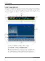
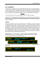
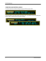
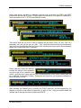
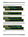
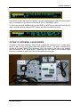
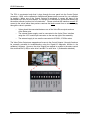
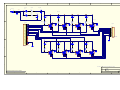
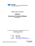
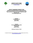
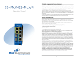
LEADS Addendum For use with the following user manuals: Model T700 Manual PN 06873 Model 700E Manual PN 05621 © TELEDYNE ADVANCED POLLUTION INSTRUMENTATION (TAPI) 9480 CARROLL PARK DRIVE SAN DIEGO, CA 92121-5201 USA Toll-free Phone: 800-324-5190 Phone: 858-657-9800 Fax: 858-657-9816 Email: [email protected] Website: http://www.teledyne-api.com/ Copyright 2010-2012 Teledyne Advanced Pollution Instrumentation 05780A DCN6493 06 June 2012 LEADS Addendum INTRODUCTION The LEADS version of Models T700 and 700E software includes support for Dasibi “Dot” serial data commands, operational “Levels”, and for driving external devices via contact closure control outputs. Further an optional bolt-on valve driver assembly allows the control of external valves using these control outputs. Generally a LEADS equipped Model T700 or 700E will be used in conjunction with a XENO data logger that collects and buffers data between the various calibrators, analyzers and met gear at an air monitoring station and a remotely located central data analysis facility. LEADS is a data collection and analysis system for meteorological and environmental data. It can be used to integrate data and control instrumentation from several different manufacturers. However the first and most prevalent implementation of the LEADS system was done for TNRCC using Dasibi 5008 calibrators. Due to the desire to be backwards compatible with existing LEADS systems the “Dot” commands and “Levels” were added to the M700, M700E, and T700. For more information on the LEADS system please go to http://www.meteostar.com/. 05780A DCN6493 1 LEADS Addendum FRONT PANEL DISPLAYS The examples illustrated in this addendum show the front panel display of the Model 700E. The information is the same for the Model T700, but the front panel display is a capacitive touch screen whose interface looks significantly different from that of the Model 700E. The following illustration shows where on a T700 front panel display you will find the same information that is shown in the 700E front panel display: 2 05780A DCN6493 LEADS Addendum DOT COMMANDS The Dasibi “Dot” commands form a text-based (ASCII) data protocol that is transmitted between a control computer (XENO data logger in this case) and a calibrator or ambient gas analyzer over an RS-232 connection. The details of the protocol are beyond the scope of this document, but in its simplest form the protocol is based on a two or three digit integer preceded by a control-A and a period (.) and then followed by a “!” and a two digit checksum. For example: ^A.xxx!nn For further information on dot commands please contact TAPI Technical Support. A Model T700 or 700E equipped with LEADS software can be simultaneously operated over the same COM port using standard TAPI serial data commands and is compatible with APIcom. APIcom versions 3.7.3 and after include an added feature that allows a user to edit, upload and download level tables. LEVELS A level is a combination of an action, concentration value, if applicable, an output flow rate and a configuration for one or both of two status output words. Up to twenty levels can be defined and used with the Model T700 or 700E using a range of numbers from 0-98; level 99 is reserved for standby. The actions that are possible with levels include Generate gas, conduct a Gas Phase Titration (GPT), conduct a Gas Phase Titration Pre Set (GPTPS) or Manual operation of the calibrator’s mass flow controllers and, or ozone generator, if installed. Unlike the sequences in a T700/M700/M700E, levels do not include time information such as start time or duration; rather, levels must be executed either by an operator at the calibrator’s front panel or through a serial data operation over the RS-232 or Ethernet ports. GENERATING A GAS USING A LEVEL FROM THE FRONT PANEL To run an existing defined level press GEN, then LEVL Then select the desired level by pressing the buttons below the 10’s or 1’s digit and finally the ENTR button. 05780A DCN6493 3 LEADS Addendum CREATING AND EDITING LEVELS To create a new level or edit an existing level press SETUP and then LEVL If no level exists or you wish to add a level press INS. If you wish to edit a level then press PREV or NEXT to select the level you wish to change. 4 05780A DCN6493 LEADS Addendum Select what activity you wish to undertake with the level by pressing the PREV and NEXT buttons and then the ENTR button. Please consult the manual for your respective calibrator for more information on GPT, GPTPS and MANUAL modes. Then select what gas you wish to flow by pressing the gas button (Zero, O3, NO, SO2, etc.) repeatedly until you get the gas you wish. Then using the buttons below the concentration value enter the concentration that you wish to flow; pressing the button below the units display allows you to change the units of operation. Please note that unless the calibrator includes an optional ozone generator you will not get O3 as a selection, and unless a gas has been setup under the SETUP|GAS|SOURCE GAS CONFIG menu there will be no selection for the gas of interest. Please see the manual for your respective calibrator for more information on this. After selecting the desired gas by pressing the ENTR button,you will be prompted by the analyzer to input the total amount of gas that you wish to flow. Using the buttons below the relevant digit to change the value and then press ENTR. 05780A DCN6493 5 LEADS Addendum If you are creating a new level, then you will be prompted to assign the action to a level (0-99). Press the EDIT button and then the buttons below the 0 and 10’s to select the level you wish to use, then ENTR to store the level and level number. At this point you will have set the type of action, the type of gas and the flow rate out of the analyzer for the new or modified level. To configure the status block, which determines which of the rear panel CONTROL OUTPUTS are energized, press the SET> key. If the status block is disabled press the EDIT key, then the ON key, and then the ENTR key. Edit the status block bit pattern by selecting the appropriate bit using the <CH and CH> buttons and by pressing the button below the [1], or [0] button. Press ENTR to store the configuration. The Most Significant Bit (MSB) is the first bit on the left and corresponds with CONTROL OUTPUT-1 on the rear panel. In turn the MSB corresponds with VALVE DRIVE-1 on the optional external valve driver option attached to the calibrator’s rear panel. To select the second status block press SET> and follow the steps above. The second status block does not correspond to any physical output but is used to communicate status over the serial data port. 6 05780A DCN6493 LEADS Addendum Press ENTR or EXIT depending on whether you have enabled and, or edited the second status block. Press Exit until you return to either the SETUP or GENERATE menus To edit, insert or delete another level press the PREV or NEXT keys to select the level that you wish to change and then press the EDIT buttons and follow the steps from above. OPTION 73, EXTERNAL VALVE DRIVER An external valve driver assembly, Option 73, is available that can drive up to 8, 16-watt valves based on the condition of the status block bits described above. The option, pictured below, consists of a custom Printed Circuit Assembly (PCA) that mounts to the back of the calibrator and a universal AC-to-DC power supply. Depending upon the capacity of the external supply either four (standard) or eight valves can be simultaneously energized. 05780A DCN6493 7 LEADS Addendum The PCA is constructed such that it plugs through the rear panel into the Control Output connector, J1008, on the calibrator’s motherboard (please see the manual for your calibrator for details). When one of the Control Outputs is energized, it causes the base of the associated PNP valve driver transistor, U1 through U8 to be taken to ground and thereby into the emitter-collector junction into full conduction. Please note that this interface sources DC current to the valves rather than previous versions that sinks current from an external supply through the valve in question. Valves should be connected between one of the Valve Drive outputs and one of the Return pins. The external power supply must be connected to the Valve Driver Interface using the +12V coaxial input connector on the rear top right of the assembly. The external supply in turn must be connected to 85-264V, 47-63Hz mains. The Valve Driver Outputs are mapped one-for-one to the Control Outputs 1 through 8 and can be manually actuated for troubleshooting using the Signal-I/O diagnostic function in the calibrator’s software. However, the drive outputs are mapped In reverse to the status control bits such that Bit-0 (LSB) is valve drive 8 and Bit-7 is valve drive 1. (Schematics attached). 8 05780A DCN6493 1 2 DD_71 CB_32 D1 F1 3 4 6 5 CA_182 CN_643 JP1 D 1 3 2 +12V +12a 2.70A + C2 1000 4 HEADER D2 2.70A F2 DD_62 D +12b D3 GRN + C1 1000 D4 GRN D6 GRN D5 GRN IC_307 CN_497 RS_356 R1 1100 R2 1100 R4 1100 R3 1100 1 15 2 16 3 17 4 18 5 19 6 20 7 21 8 22 9 23 10 24 11 25 12 26 13 27 14 28 C 4 4 U1 FPFS2P103A 4 U2 FPFS2P103A 3 2 1 3 2 1 3 2 1 3 2 1 P1008 4 U3 FPFS2P103A CN_617 U4 FPFS2P103A 5 6 7 8 5 6 7 8 5 6 7 8 5 6 7 8 JP2 1 2 3 4 5 6 7 8 9 10 11 12 C Weidmuller152286 +12b D7 GRN D8 GRN D10 GRN D9 GRN IMCV 1,5/14-G-3,81 4 3 2 1 3 2 1 4 U5 FPFS2P103A U6 FPFS2P103A 5 6 7 8 U7 FPFS2P103A 5 6 7 8 U8 FPFS2P103A 4 5 6 7 8 4 B R8 1100 R7 1100 3 2 1 R6 1100 3 2 1 R5 1100 5 6 7 8 B A A DCN 4295 Printed Documents Are Uncontrolled 1 Title SCH, External Valve Interface PCA 05697 Size Number B 05698 Date: File: 2 3 4 5 Revision B 8-Dec-2006 Sheet1 of 2 N:\PCBMGR\05696.leads.rear.panel.adapter.dn\Protel\05696.ddb Drawn By: 6 1 2 3 4 6 5 D D P1020 mates with positions 7 & 8 of J1020 on motherboard J1020 P1020 1 2 AnalogOut4+ AnalogOut4- HEADER 2 CN0000226 J1004 1 3 2 4 P1004 1 2 3 4 5 6 7 8 9 10 IMCV 1,5/2-G-3,81 CN0000645 1 11 2 12 3 13 4 14 5 15 6 16 7 17 8 18 9 19 10 20 10 HEADER CN0000395 C J1006 P1006 1 2 3 4 5 6 7 8 9 10 1 11 2 12 3 13 4 14 5 15 6 16 7 17 8 18 9 19 10 20 10 HEADER CN0000395 IMCV 1,5/10-G-3,81 CN0000564 J1017 IMCV 1,5/10-G-3,81 CN0000564 P1017 SysOK+ 1 2 3 4 5 6 7 8 9 10 11 12 B C 12 HEADER CN0000394 StatusReturn DigGrnd 1 13 2 14 3 15 4 16 5 17 6 18 7 19 8 20 9 21 10 22 11 23 12 24 B IMCV 1,5/12-G-3,81 CN0000565 A A Title SCH, External Valve Interface PCA 05697 DCN 4295 Printed Documents Are Uncontrolled 1 Size Number B 05698 Date: File: 2 3 4 5 Revision B 8-Dec-2006 Sheet2 of 2 N:\PCBMGR\05696.leads.rear.panel.adapter.dn\Protel\05696.ddb Drawn By: 6