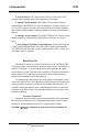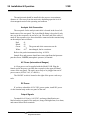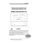
1
MODEL
319R
OXYGEN DETECTOR
INSTRUCTION MANUAL
P/N M59608
ECO# 95-416
7/10/95
TELEDYNE BROWN EGINEERING
Analytical Instruments
Copyright © 1993 Teledyne Brown Engineering Analytical Instruments
All Rights Reserved.
No part of this manual may be reproduced, transmitted, transcribed, stored in a retrieval system,
or translated into any other language or computer language in whole or in part, in any form or by any
means, whether it be electronic, mechanical, magnetic, optical, manual, or otherwise, without the
prior written consent of Teledyne Brown Egineering Analytical Instruments (TBE), 16830 Chestnut
Street, City of Industry, CA 91749-1580.
Warranty
This equipment is sold subject to the mutual agreement that it is warranted by us free from
defects of material and of construction, and that our liability shall be limited to replacing or repairing
at our factory (without charge, except for transportation), or at customer plant at our option, any
material or construction in which defects become apparent within one year from the date of shipment,
except in cases where quotations or acknowledgements provide for a shorter period. The Micro-Fuel
Cell warranty period begins on the date of shipment from Teledyne. Components manufactured by
others bear the warranty of their manufacturer. This warranty does not cover defects caused by wear,
accident, misuse, neglect or repairs other than those performed by Teledyne or an authorized service
center. We assume no liability for direct or indirect damages of any kind and the purchaser by the
acceptance of the equipment will assume all liability for any damage which may result from its use or
misuse.
We reserve the right to employ any suitable material in the manufacture of our apparatus, and to
make any alterations in the dimensions, shape or weight of any parts, in so far as such alterations do
not adversely affect our warranty.
IMPORTANT NOTICE
This instrument is intended to be used as a tool to gather valuable data. The information
provided by the instrument may assist the user in eliminating potential hazards caused by the user’s
process; however, it is essential that all personnel involved in the use of the instrument or its interface, with the process being measured, be properly trained in the process itself, as well as all instrumentation related to it.
The safety of personnel is ultimately the responsibility of those who control process conditions.
While this instrument may be able to provide early warning of imminent danger, it has no control
over process conditions, and it can be misused. In particular, any alarm or control systems installed
must be tested and understood, both as to how they operate and as to how they can be defeated. Any
safeguards required such as locks, labels, or redundancy, must be provided by the user or specifically
requested of Teledyne when the order is placed.
The purchaser must be aware of the hazardous process conditions inherent in the process(es) he
uses. He is responsible for the training of personnel, for providing hazard warning methods and
instrumentation per the appropriate standards, and for ensuring that hazard warning devices and
instrumentation are maintained and operated properly.
TBE, the manufacturer of this instrument, cannot accept responsibility for conditions beyond its
knowledge and control. No statement expressed or implied by this document or any information
disseminated by the manufacturer or its agents, is to be construed as a warranty of adequate
safety control under the user’s process conditions.
TELEDYNE BROWN EGINEERING
Analytical Instruments
Table of Contents
1.0 Introduction
Main Features ............................................................................................... 1
Micro-Fuel Cell ............................................................................................ 2
Z-2 Cell Warranty Conditions ...................................................................... 2
2.0 Installation & Operation
Precautions.................................................................................................... 3
Location & Mounting ................................................................................... 3
Analysis Unit Connection ............................................................................. 4
AC Power ..................................................................................................... 4
DC Power ..................................................................................................... 4
Output Signals .............................................................................................. 4
Alarm Terminal Connection ......................................................................... 5
Sensor Installation or Replacement .............................................................. 5
Setting Alarms .............................................................................................. 6
Calibration .................................................................................................... 7
3.0 Maintenance
Replacing the Fuse........................................................................................ 9
Replacing the Sensor .................................................................................... 10
Z-2 Cell Warranty Conditions ...................................................................... 11
Appendix
Specifications................................................................................................ 13
Spare Parts List ............................................................................................. 14
Drawing List ................................................................................................. 15
Material Safety Data Sheet ........................................................................... 16
TELEDYNE BROWN EGINEERING
Analytical Instruments
TELEDYNE BROWN EGINEERING
Analytical Instruments
319R
Introduction 1.0
Introduction
The Teledyne Brown Engineering Analytical Instruments (TBE)
Model 319R Oxygen Detector measures the percent of oxygen in a wide
range of gases and gas mixtures. Modular and compact design provide
outstanding performance and reliable on-line monitoring and make the
319R virtually maintenance-free.
A special range on the 319R enables you to calibrate in ambient air.
The Micro-Fuel Cell produces an output that corresponds linearly to the
oxygen concentration; the absence of oxygen produces zero current. This
means you can use ambient air (20.9% oxygen) to calibrate, eliminating
the need for special span gases.
The Model 319R contains a main PC board and power supply/interconnection board housed in a rack mount enclosure. The oxygen probe can
be separated from the unit by as much as 6 feet, depending on the level of
electromagnetic noise in the operating environment.
Main Features
1. Two Ranges of Analysis. The Model 319R Oxygen Monitor
features two analysis ranges: 0–200 PPM and 0–1999 PPM. A 0-25%
range is accessible only during calibration to allow calibration in air.
2. Liquid Crystal Display Digital Readout. The digital front panel
LCD continuously displays and updates O2 monitoring levels and displays
values when calibrating the instrument and setting the alarms. Note that the
display will not read higher than 199.9 on the 200 PPM range and 1999 on
the 2000 PPM range.
3. Percent of Range Alarms. Three (3) alarm relays are provided:
one high and one low alarm, which are user adjustable, and one low alarm,
factory set as a cell fail alarm at 2% of full scale.
TELEDYNE BROWN ENGINEERING
Analytical Instruments
1
1.0 Introduction
319R
4. Proven Sensor. The 319R uses the Class Z-2 Micro-Fuel Cell,
warranted for 6 months, with a life expectancy of 6 months.
5. Analog Voltage Output. The Model 319R provides customer
connections to external devices, such as computers, recorders, alarms, etc.,
at 0–10 VDC, negative ground, plus contact closures for range identification. Custom voltage outputs, either grounded or isolated, are available as
options.
6. Analog Current Output. The Model 319R has a 4–20 mA current
output suitable for connection to external devices that use a 4–20 mA
input.
7. Over-Range/Cell Failure Visual Indicator. The Model 319R has
a LED (Light Emitting Diode) to the left of the Liquid Crystal Display.
The LED will blink when the oxygen reading exceeds 105% of scale, or a
cell failure alarm is activated.
Micro-Fuel Cell
The Model 319R uses a Class Z-2 Micro-Fuel Cell. The Micro-Fuel
Cell measures the concentration of oxygen in a gas stream. The analysis is
specific for oxygen; i.e. the measuring cell will not generate an output
current unless oxygen is present in the sample gas. Therefore, the analyzer
has an absolute zero, and requires no zero gas. Span calibration is performed with atmospheric air as the span gas.
To eliminate any inaccuracies due to the positive temperature coefficient of the Micro-Fuel Cell, a thermistor circuit and network of precision
resistors produce a negative coefficient of matching characteristics. The
variable element (thermistor) in the compensation network is in the same
assembly as the Micro-Fuel Cell, exposing both devices to the same temperature conditions.
Warranty Conditions
Customers having warranty claims must return the cell in question to
the factory for evaluation. If it is determined that failure is due to faulty
material or workmanship the cell will be replaced free of charge.
CAUTION: Evidence of tampering or abuse will render the warranty null
and void.
2
TELEDYNE BROWN ENGINEERING
Analytical Instruments
319R
Installation & Operation 2.0
Installation & Operation
Precautions
1. Read this chapter in its entirety before installing the unit.
2. Upon receipt of the instrument, inspect the entire unit for
damage. Notify the shipper if any damage is found. Check the
unit, probe, and included accessories for broken or loose parts.
3. The sample must be free of entrained solids and water. A high
humidity sample is ideal since it will prevent water loss from
the cell electrolyte.
4. The Micro-Fuel Cell sensor electrolyte is caustic. Do not
attempt to open or repair the sensor. Leaking or exhausted
sensors should be disposed of in accordance with local
regulations. Please refer to the Material Safety Data Sheet in the
Appendix to learn about potential hazards and corrective action
in case of accident.
5. Do not scratch, puncture, or damage the sensing membrane of
the Micro-Fuel Cell sensor. Damage to the membrane will
require replacement of the sensor.
Location & Mounting
The unit is designed to be panel-mounted in a general purpose area,
away from moisture and the elements. The unit should be installed at
viewing level in a sheltered area.
Refer to the Outline diagram (dwg. C-57490) for the physical dimensions of the analyzer.
TELEDYNE BROWN ENGINEERING
Analytical Instruments
3
2.0 Installation & Operation
The analysis unit should be installed in the process at a maximum
distance of 6 feet away from the main unit, depending upon the level of
electromagnetic noise in the operating environment.
Analysis Unit Connection
The receptacle for the analysis unit cable is located in the lower lefthand corner of the rear panel. The 6-pin Minifit fitting is keyed to fit only
one way in the receptacle; do not force it in. The other end of the cable is
made of four separate wires; these should be connected to the terminal strip
on the analysis unit as follows:
Red:
Black:
Green:
White:
#1
#2
#3
}
#4
The green and white connectors can be
interchanged, but be consistent.
Refer to the probe interconnection dwg. A-58154.
Sample flow and pressure should not create significant backpressure
past the sensor; 2 SCFH (atmospheric pressure) is nominal.
AC Power (International Ranges)
A 6-foot power cord is supplied with the Model 319R. Plug the
female end of the power cord into the receptacle in the upper left-hand
corner of the rear panel. The unit is now ready to be plugged into an AC
power source (85-264 VAC, 47-440 Hz).
The ON/OFF switch is located to the right of the power cord receptacle.
DC Power
If you have ordered the 10-36 VDC power option, install DC power
via the terminal strip on the rear panel of the unit.
Output Signals
Terminals for 4-20 mA, 0-10 VDC, and range identification are
labeled on the rear panel of the analyzer, along with high alarm, low alarm,
and sensor failure block terminals.
4
TELEDYNE BROWN ENGINEERING
Analytical Instruments
319R
319R
Installation & Operation 2.0
Alarm Terminal Connection
SPDT relay contacts are provided for each of the 3 alarms. There are
9 terminals available on the back panel of the system for alarm circuit
connection. The explanation for the relay terminals abbreviations is as
follows:
NC = Normally closed
C = Common
NO= Normally open
The alarm relay circuits are designed for failsafe operation, meaning
that the relays are activated (energized) during normal operation. If power
fails, or if an alarm setpoint is exceeded, the relay will become de-energized.
Sensor Installation or Replacement
CAUTION: The sensor electrolyte is caustic. Do not let it come in contact
with skin. If it does, immediately flush affected area with water.
Consult the Emergency First Aid procedures in the Material
Safety Data Sheet in the Appendix.
Do not attempt to open or repair the sensor. Leaking or exhausted sensors should be disposed of in accordance with
local regulations. Please refer to the Material Safety Data Sheet
in the Appendix to learn about potential hazards and corrective
action in case of accident.
To install the cell:
1. Turn the unit off by placing the power switch (on the rear panel
of the analyzer) in the OFF position.
2. Disconnect the red and black leads from the terminal strip.
Remove the spent cell by pulling up on it and twisting slightly.
3. Remove the new Micro-Fuel Cell from its protective bag.
CAUTION: Do not scratch, puncture, or damage the sensing membrane of
the Micro-Fuel Cell sensor. Damage to the membrane will
require replacement of the sensor.
4. Attach the red lead of the new cell to terminal #1 and the black
lead to terminal #2.
5. Replace the cell on the cell holder by pushing and twisting until
it strikes bottom.
TELEDYNE BROWN ENGINEERING
Analytical Instruments
5
2.0 Installation & Operation
Setting Alarms
The alarms can be adjusted over the full scale range, and they are set
as a percent of full scale. Thus, an alarm set to indicate 192 on the display
while on the 200 PPM O2 range will activate at 192 PPM O2 on the 200
PPM O2 range and at 1920 O2 on the 2000 O2 range (96% of full scale). To
set the alarms:
1. Place the range switch located below the front panel display in
the 2000 PPM range position (or highest range available).
2. Place the power switch in the ON position.
3. To set the high alarm, hold down the SET HI ALARM button
while turning the potentiometer to the right of the button until
the display reads the desired concentration.
4. To set the low alarm, hold down the SET LO ALARM button
while turning the potentiometer to the right of the button until
the display reads the desired concentration.
5. Remember, the System/Cell Failure alarm is factory set at 2%
of full scale; should this alarm trigger, the LED to the left of the
front panel display will blink.
6
TELEDYNE BROWN ENGINEERING
Analytical Instruments
319R
319R
Installation & Operation 2.0
Calibration
To calibrate the 319R:
1. Place the power switch in the ON position.
2. Allow the LCD reading to stabilize.
3. Expose the sensor to ambient air (20.9%) or instrument grade
air. If the analyzer goes overrange, the display will go blank
and the LED to the left of the display will blink. Hold down the
SPAN button until the LED stops blinking.
4. While holding down the SPAN AT 20.9% button, adjust the
potentiometer to the right of the button until the display is
stable and reads 20.9%.
5. Release the button. The unit is now calibrated.
6. The alarms will be disabled for about 25 seconds after the
SPAN button is released. Disabling the alarms allows air to be
purged from the sample system without tripping any alarm set
below span, or 21%.
NOTE: Do not attempt to adjust any alarm setpoints while the alarms are
disabled during the 25-second period.
TELEDYNE BROWN ENGINEERING
Analytical Instruments
7
2.0 Installation & Operation
8
TELEDYNE BROWN ENGINEERING
Analytical Instruments
319R
319R
Maintenance 3.0
Maintenance
Replacing the Fuse
If the unit will not turn on when plugged in and switched ON (via the
power switch), or you suspect a blown fuse, replace the fuse using the
following procedure:
1. Disconnect the AC power and place the power switch located
on the rear panel in the OFF position.
2. The fuse is located next to the power cord receptacle in the
upper left-hand corner of the rear panel. Remove the power
cord from the receptacle.
3. Insert a small flat-blade screwdriver into the slot in the
receptacle wall nearest the fuse and gently pry open the fuse
receptacle. The fuse holder will slide out. The fuse in use is
visible in the clip. To open the spare fuse compartment, push on
one end until it slides out.
4. Remove the bad fuse and replace it with a 5X20 mm 1A, 250V
fast acting fuse for AC units (TBE P/N F-1189 ), or 1/2A fast
acting fuse for DC units (P/N F-51).
Figure 5-1: Replacing the fuse (AC power).
TELEDYNE BROWN ENGINEERING
Analytical Instruments
9
3.0 Maintenance
319R
5. Replace the fuse holder into its receptacle, pushing in firmly
until it clicks.
In units with DC power, the fuse is located on the rear panel above the
ON/OFF switch. Open the fuse holder by unscrewing and removing the
knob marked FUSE. The fuse will be located inside the knob.
Replacing the Sensor
The characteristics of the Micro-Fuel Cell are similar to those of a
mercury battery in that both provide an almost constant output through
their useful life, and then fall off sharply towards zero at the end. If the
sample being analyzed has a low oxygen concentration, cell failure will
probably be indicated by the inability to properly calibrate the analyzer.
You will find that very little adjustment of the span potentiometer will be
required to keep the analyzer calibrated properly during the duration of a
given cell’s useful life. If large or many turn adjustments (clockwise) are
required to calibrate the instrument, or calibration cannot be achieved
within the range of the control, the cell needs replacing. Read the following
section (Cell Warranty) before replacing the cell. Cell installation instructions are in Chapter 2: Cell Installation.
In addition, if the LCD displays “00.0” when the unit is plugged in,
and the power switch is in the ON position, the sensor needs to be replaced.
IMPORTANT: After replacing the Micro-Fuel Cell, proceed to Chapter 2:
Calibration.
To offset the possibility of not having a replacement cell available
when needed, a spare cell can be ordered shortly after the instrument is in
service, and each time after cell replacement thereafter.
NOTE: Do not stockpile cells, as the cell warranty begins on date of
shipment.
Only one cell per instrument should be in reserve. The spare cell
should be carefully stored in an area not subject to large variations in
ambient temperature (75° F nominal), and in such a way to eliminate any
possibility of damage. Under no circumstance should you disturb the
integrity of the cell package until the cell is to be used. If the cell package
is punctured and air permitted to enter, the cell will immediately start to
react to the presence of oxygen.
10
TELEDYNE BROWN ENGINEERING
Analytical Instruments
319R
Maintenance 3.0
Warranty Conditions
The Class Z-2 cell used in the 319R is warranted for six (6) months of
service from the date of shipment. Customers having warranty claims must
return the cell in question to the factory for evaluation. If it is determined
that failure is due to faulty material or workmanship, the cell will be
replaced free of charge.
CAUTION: Evidence of tampering or abuse will render the warranty null
and void.
TELEDYNE BROWN ENGINEERING
Analytical Instruments
11
3.0 Maintenance
12
319R
TELEDYNE BROWN ENGINEERING
Analytical Instruments
319R
Appendix
Appendix
Specifications
Ranges:
Sensitivity:
Signal Output:
Display:
Alarms:
Accuracy:
Response:
Operating Temp. Range:
Power:
Enclosure:
Cell Type:
Cell Warranty:
Cell Life (Expected):
Dimensions:
0–200 PPM, 0–1999 PPM O2, and 0–
25% calibration range
1% of full scale
Standard: 0–10 VDC, negative ground
4-20 mA, negative ground
plus contact closures for range
identification.
Digital 7 segment, 3½-digit LCD with
over range indicator.
One high alarm, adjustable & fail-safe.
One low alarm, adjustable & fail-safe.
One low alarm, fixed at 2% full scale and
fail-safe.
±2% of full scale at constant temperature
and pressure of calibration
±5% of full scale throughout operating
temperature range (once temperature
equilibrium has been reached).
90% of full scale in 35 seconds.
32 °F to 122 °F (0°C to 50°C)
85-264 VAC, 47-440 Hz or 10-36 VDC,
user specified, 10 W max.
General purpose, panel mount
Z-2
6 months
6 months
2.75 "H × 6.0 "W × 2.75 "D
(63.5 mm × 152.4 mm × 63.5 mm)
Faceplate: 3.75 "H × 7.0 "W
(95.25 mm × 177.8 mm)
Probe unit: 4.0 "H × 6.0 "W × 3 "D
(101.6 mm × 152.4 mm × 76.2 mm)
TELEDYNE BROWN ENGINEERING
Analytical Instruments
13
Appendix
319R
Spare Parts List
QTY.
1
1
1
4
4
1
P/N
C57304
A33748
C6689-Z2
F1189
F51
A59264
DESCRIPTION
PC board, main
Thermistor assembly
Micro-Fuel Cell, Z-2
Fuse, 1A (AC)
Fuse, ½A (DC)
Probe to analyzer cable, 6 feet
A minimum charge of US $20.00 is applicable to spare parts orders.
IMPORTANT: Orders for replacement parts should include the part number and the model and serial number of the system for
which the parts are intended.
Send orders to:
TELEDYNE BROWN ENGINEERING
Analytical Instruments
16830 Chestnut Street
City of Industry, CA 91749-1580
Telephone: (818) 961-9221
TWX: (910) 584-1887 TDYANYL COID
Fax: (818) 961-2538
or your local representative
14
TELEDYNE BROWN ENGINEERING
Analytical Instruments
319R
Appendix
Drawing List
C-57490
A-58154
D-57302
C-57305
C-57307
B-58123
Note:
Outline diagram
Probe interconnection diagram
Electronic PCB schematic diagram
Power supply PCB schematic diagram
Power supply PCB assembly diagram
Analysis unit (probe) outline
319R analyzers with 25% and 100% range modifications incorporate
the following changes:
1.
2.
3.
4.
100% range modified circuit changes:
JP2 - connects pins 1 and 2
R52 is 12.5K
R30 is 7.5K
R35 is 1.5K
1.
2.
3.
4.
25% range modified circuit changes:
JP2 - connects pins 1 and 2
R52 is 50K
R30 is 28K
R35 is 11K
TELEDYNE BROWN ENGINEERING
Analytical Instruments
15
Appendix
319R
Material Safety Data Sheet
Section I – Product Identification
Product Name: Micro-Fuel Cells and Super Cells, all classes except A-2C, A-3,
and A-5.
Electrochemical Oxygen Sensors, all classes except R-19.
Mini-Micro-Fuel Cells, all classes.
Manufacturer: Teledyne Brown Engineering Analytical Instruments
Address:
16830 Chestnut Street, City of Industry, CA 91749
Phone:
(818) 961-9221
Customer Service: Extension 222
Environmental Health
and Safety: Extension 230
Date Prepared : 04/26/95
Section II – Hazardous Ingredients/Composition
Material or
Component
TLV
C.A.S. #
Quantity
OSHA PEL ACGIH
Lead (Pb)
7439-92-1
3–20 gms
0.05 mg/m3
0.15 mg/m3
Potassium Hydroxide
Solution 15% (KOH)
1310-58-3
1–5 ml
None
2 mg/m3
Section III – Physical/Chemical Characteristics
Material
Specific Vapor
Appearance Boiling
or Compo- Point (°C) Gravity Pressure
nent
11.34
1744
na
Lead
1320
Potassium
Hydroxide
16
Melting DensityEvap. Solubility Odor
Point
Rate in Water
(°C)
Insoluble Solid, silver
na na
gray, odorless
328
2.04
na
na
na
360
TELEDYNE BROWN ENGINEERING
Analytical Instruments
Complete White or
slightly
yellow,
no odor
319R
Appendix
Section IV – Fire and Explosion Hazard Data
Flash Point:
na
Flammable Limits:
na
LEL:
na
UEL:
na
Extinguishing Media:
Use extinguishing media appropriate to surrounding fire
conditions. No specific agents recommended.
Special Fire Fighting
Equipment:
Wear NIOSH/OSHA approved self-contained breathing
apparatus and protective clothing to prevent contact with
skin and eyes.
Unusual Fire and Explosion
Hazards:
Emits toxic fumes under fire conditions.
Section V – Reactivity Data
Stability:
Stable
Incompatibilities:
Aluminum, organic materials, acid chlorides, acid
anhydrides, magnesium, copper. Avoid contact with acids
and hydrogen peroxide > 52%.
Hazardous Decomposition of
Byproducts:
Hazardous Polymerization:
Toxic fumes
Will not occur.
Section VI – Health Hazard Data
Routes of Entry:
Inhalation:
Highly unlikely
Ingestion:
May be fatal if swallowed.
Skin:
The electrolyte (potassium hydroxide) is corrosive; skin
contact may cause irritation or chemical burns.
Eyes:
The electrolyte (potassium hydroxide) is corrosive; eye
contact may cause irritation or severe chemical burns.
Acute Effects:
The electrolyte is harmful if swallowed, inhaled or
adsorbed through the skin. It is extremely destructive to
tissue of the mucous membranes, stomach, mouth, upper
respiratory tract, eyes and skin.
Chronic Effects:
Prolonged exposure with the electrolyte has a destructive
effect on tissue.
Chronic exposure to lead may cause disease of the blood
and blood forming organs, kidneys and liver, damage to
the reproductive systems and decrease in fertility in men
and women, and damage to the fetus of a pregnant
woman. Chronic exposure from the lead contained in
this product is extremely unlikely.
TELEDYNE BROWN ENGINEERING
Analytical Instruments
17
Appendix
319R
Signs and Symptoms of
Exposure:
Contact of electrolyte with skin or eyes will cause a
burning sensation and/or feel soapy or slippery to touch.
Other symptoms of exposure to lead include loss of
sleep, loss of appetite, metallic taste and fatigue.
Carcinogenicity:
Lead is classified by the IARC as a class 2B carcinogen
(possibly carcinogenic to humans)
OSHA:
Where airborne lead exposures exceed the OSHA action
level, refer to OSHA Lead Standard 1910.1025.
NTP:
na
Medical Conditions Generally
Aggravated by Exposure:
Lead exposure may aggravate disease of the blood and
blood forming organs, hypertension, kidneys, nervous
and possibly reproductive systems. Those with preexisting skin disorders or eye problems may be more susceptible to the effects of the electrolyte.
Emergency First Aid Procedures:
In case of contact with the skin or eyes, immediately
flush with plenty of water for at least 15 minutes and
remove all contaminated clothing. Get medical attention
immediately.
If ingested, give large amounts of water and DO NOT
INDUCE VOMITING. Obtain medical attention immediately.
If inhaled, remove to fresh air and obtain medical
attention immediately.
Section VII – Precautions for Safe Handling and Use
NOTE: The oxygen sensors are sealed, and under normal circumstances,
the contents of the sensors do not present a health hazard. The
following information is given as a guide in the event that a cell
leaks.
Protective measures
during cell replacement:
Before opening the bag containing the sensor cell, check
the sensor cell for leakage. If the sensor cell leaks, do
not open the bag. If there is liquid around the cell while
in the instrument, wear eye and hand protection.
Cleanup Procedures:
Wipe down the area several times with a wet paper
towel. Use a fresh towel each time. Contaminated paper
towels are considered hazardous waste.
18
TELEDYNE BROWN ENGINEERING
Analytical Instruments
319R
Appendix
Section VIII – Control Measures
Eye Protection:
Chemical splash goggles
Hand Protection:
Rubber gloves
Other Protective Clothing:
Apron, face shield
Ventilation:
na
Section IX – Disposal
Both lead and potassium hydroxide are considered poisonous substances and are regulated under
TSCA and SARA Title III.
EPA Waste Number:
D008
California Waste Number:
181
DOT Information:
RQ Hazardous Waste Solid N.O.S. (Lead), 9, UN3077,
PG III
Follow all Federal, State and Local regulations.
Section X – References
Material Safety Data Sheets from J.T. Baker Chemical, Aldrich, Malinckrodt, ASARCO
U.S. Department of Labor form OMB No. 1218-0072
Title 8 California Code of Regulations
TSCA
SARA Title III
CFR 49
CFR 29
CFR 40
NOTE: The above information is believed to be correct and is offered for your
information, consideration, and investigation. It should be used as a
guide. Teledyne Brown Engineering Analytical Instruments shall not be
held liable for any damage resulting from handling or from contact with
the above product.
TELEDYNE BROWN ENGINEERING
Analytical Instruments
19