1
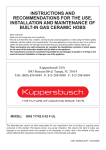
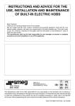
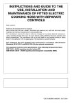
Instructions for the installation
and advice for the maintenance
EX/60 4G AI FUND
EX/70 5G AI TR FUND - EX/70 5G AI AL TR FUND
Instructions Manual
EX/60 4G AI FUND
EX/70 5G AI TR FUND - EX/70 5G AI AL TR FUND
COD. 04038GBTK - 24.05.2005
DESCRIPTION OF THE HOT PLATES
TYPES: EX/60 4G AI FUND - EX/70 5G AI TR FUND - EX/70 5G AI AL TR FUND
1 Ultra rapid burner
2 Rapid gas burner
3 Semirapid gas burner
4 Auxiliary gas burner
5 Enamelled steel pan support 2F
6 Enamelled steel pan support 1F
7 Burner n° 1 control knob
8 Burner n° 2 control knob
9 Burner n° 3 control knob
10 Burner n° 4 control knob
11 Electric ignition button
of
of
of
of
3100 W
2800 W
1750 W
1000 W
Attention: this appliance has been manufactured for domestic use only and it employment by
private person.
2
USE
1) BURNERS
Burners
Power ratings
A diagram is screen-printed above each knob on
the front panel. This diagram indicates to which
burner the knob in question corresponds. After
having opened the gas mains or gas bottle tap, light
the burners as described below:
- Manual ignition
Push and turn the knob corresponding to the
required burner in an anticlockwise direction until it
reaches the full on position (large flame fig. 1), then
place a lighted match near the burner.
- Automatic electrical ignition
Push and turn the knob corresponding to the
required burner in an anticlockwise direction until it
reaches the full on position (large flame fig. 1), then
depress the knob.
- Lighting burners equipped with flame failure
device
The knobs of burners equipped with flame failure
device must be turned in an anticlockwise direction
until they reach the full on position (large flame
fig.1) and come to a stop. Now depress the knob in
question and repeat the previously indicated
operations.
Keep the knob depressed for about 10 seconds
once the burner has ignited.
Ultra rapid
Rapid
Semirapid
Auxiliary
3100
2800
1750
1000
Pan Ø in cm
24 ÷ 26
20 ÷ 22
16 ÷ 18
10 ÷ 14
WARNINGS:
- Burners with flame failure device may only be
ignited when the relative knob has been set to
the Full on position (large flame fig. 1).
- Matches can be used to ignite the burners in a
blackout.
- Never leave the appliance unattended when
the burners are being used. Make sure there
are no children in the near vicinity. Particularly
make sure that the pan handles are correctly
positioned and keep a chek on foods requiring
oil and grease to cook since these products
can easily catch fire.
- Never use aerosols near the appliance when it
is operating.
- If the built-in hot plate has a lid, any spilt food
should be immediately removed from this
before it is opened. If the appliance has a
glass lid, this could shatter when the hot plate
becomes hot. Always switch off all the burners
before closing the lid.
HOW TO USE THE BURNERS
Bear in mind the following indications in order to
achieve maximum efficiency with the least possible
gas consumption:
- Use adequate pans for each burner (consult the
following table and fig. 2).
- When the pan comes to the boil, set the knob to
the reduced rate position (small flame fig. 1).
- Always place a lid on the pans.
- Use only pan with a flat bottom.
FIG. 1
FIG. 2
3
USE
Notes:
Use of a gas cooking appliance produces heat and moisture in the room in which it is installed. The
room must therefore be well ventilated by keeping the natural air vents clear (fig. 3) and by
activating the mechanical aeration device (suction hood or electric fan fig. 4 and fig. 5).
Intensive and lengthy use of the appliance may require additional ventilation. This can be achieved
by opening a window or by increasing the power of the mechanical exhausting system if installed.
(*) AIR INLET: SEE INSTALLATION CHAPTER (PARAGRAPHS 5 AND 6)
FIG. 3
FIG. 4
4
FIG. 5
CLEANING
- The exact position of the pan support is
established by the rounded corners, which
should be set towards the side edge of the hot
plate.
- Do not force the taps if they are difficult open
or close. Contact the technical assistance
service for repairs.
- Correctly preserve the plate after use by
treating it with special products, easily
available on the market. This will keep the
surface of the plate clean and bright. The
operation will also prevent the formation of
rust.
- Don’t use steam jets for the equipment
cleaning.
IMPORTANT:
Always disconnect the appliance from the gas
and electricity mains before carrying out any
cleaning operation.
2) HOT PLATE
Periodically wash the hot plate, the enamelled stell
pan support, the enamelled burner caps "C" and the
burner heads "T" (see fig. 6) with lukewarm soapy
water.
Following this, all parts should be thoroughly rinsed
and dried. Never wash them while they are still
warm and never use abrasive powders.
Do not allow vinegar, coffee, milk, salted water,
lemon or tomato juice from remaining in contact
with the enamelled surfaces for long periods of
time.
WARNINGS:
Comply with the following instructions, before
remounting the parts:
- Check that burner head "T" (fig. 6) slots have
not become clogged by foreign bodies.
- Check that enamelled burner cap "C" (fig. 6)
have correctly positioned on the burner head.
It must be steady.
FIG. 6
5
INSTALLATION
The appliance belongs to class 3 and is
therefore subject to all the provisions
established by the provisions governing such
appliances.
TECHNICAL INFORMATION
FOR THE INSTALLER
Installation, adjustments of controls and
maintenance must only be carried out by a
qualified engineer.
4) FIXING THE HOT PLATE
The hot plate has a special seal which prevents
liquid from infiltrating into the cabinet. Strictly
comply with the following instructions in order to
correctly apply this seal:
- Detach the seals from their backing, checking that
the transparent protection still adheres to the seal
itself.
- Overturn the hot plate and correctly position seal
"E" (fig. 9) under the edge of the hot plate itself, so
that the outer side of the seal perfectly matches
the outer perimetral edge of the hot plate. The
ends of the strips must fit together without
overlapping.
- Evenly and securely fix the seal to the hot plate,
pressing into place with the fingers and remove the
strip of protective paper from the seal and set the
plate into the hole made in the cabinet.
- Fix the hob with the proper brackets "S" and fit
the prominent part into the porthole "H" on the
bottom; turn the screw "F" until the bracket "S"
stick on the top (fig. 10).
- The prospective walls (left or right) that exceed
the working table in height must be at a minimum
distance from the cutting as mentionned both in
the columns and the scheme.
Incorrect installation may cause damage to
persons, animals or property for which the
Manufacturer shall not be considered
responsible.
During the life of the system, the automatic
safety or regulating devices on the appliance
may only be modified by the manufacturer or by
his duly authorized dealer.
3) INSTALLING THE HOT PLATE
Check that the appliance is in a good condition after
having removed the outer packaging and internal
wrappings from around the various loose parts. In
case of doubt, do not use the appliance and contact
qualified personnel.
Never leave the packaging materials (cardboard,
bags, polystyrene foam, nails, etc.) within
children's reach since they could become
potential sources of danger.
The measurements of the opening made in the top
of the modular cabinet and into which the hot plate
will be installed are indicated in either fig. 7. Always
comply with the measurements given for the hole
into which the appliance will be recessed (see fig. 7
and 8).
COMPLY WITH THE DIMENSIONS
(mm)
A
B
C
4F
553
473
67.5
59.5 100 min.
5F
553
473
67.5
59.5 175 min.
FIG. 7
FIG. 8
FIG. 9
6
FIG. 10
D
E
INSTALLATION
IMPORTANT INSTALLATION
INSTRUCTIONS
7) GAS CONNECTION
Before connecting the appliance, check that the
values on the data label affixed to the underside
of the hot plate correspond to those of the gas
mains in the home.
A label on the appliance indicates the regulating
conditions: type of gas and working pressure.
WARNING:
A gas hot plate can only be connected by a CORGI
Registered engineer.
Installations should be carried out in accordance
with BS 6891 1988 and must comply with the Gas
Safety Regulations.
All hot plate installations must include an isolation
tap.
GAS PRESSURE TEST
Some hot plates models have a test point fitted
under the control panel, to conduct a gas pressure
test proceed as follows:
- Turn off the gas supply.
- Remove screw in the pressure test point, place
test gauge connecting tube on test point.
- Fit a burner ring and cap onto burner assembly,
replace control knob onto corresponding control
tap for the burner.
- Turn on gas and ascertain working pressure.
After test, turn off control tap, turn off gas supply,
disconnect test gauge connecting tube. Replace the
test point screw, turn gas back on and test for
soundness. Reassemble the hotplate.
The installer should note that the appliance that
side walls should be no higher than the hot plate
itself. Furthermore, the rear wall, the surfaces
surrounding and adjacent to the appliance must
be able to withstand an overtemperature of 75 K.
The adhesive used to stick the plastic laminate
to the cabinet must be able to withstand a
temperature of not less than 150° C otherwise
the laminate could come unstuck. The appliance
must be installed in compliance with BS 6172
1990, BS 5440 part. 2 1989 and BS 6891 1988.
This appliance is not connected to a device able
to dispose of the combustion fumes. It must
therefore be connected in compliance with the
above mentioned installation standards.
Particular care should be paid to the following
provisions governing ventilation and aeration.
5) ROOM VENTILATION
To ensure correct operation of the appliance, it is
important to ensure that the room where the hot
plate is installed has sufficient ventilation, as set out
in BS 5440 part 2. 1989. See table below.
Type of appliance
Domestic
ovens
hotplates or
any
combinations
Volume of room
cubic metres
Min. size of
vent sq. cm.
5
100
Openable window
or alternative
method of
venting to the
outside
yes
5 to 10
50
yes
11 to 20
20 and above
nil
nil
yes
yes
Natural air flow must enter directly through
permanent openings in the walls of the room in
question. These must open towards the outside and
possess a minimum section of 100 cm2 see fig. 3).
It must be impossible to obstruct these openings.
Indirect ventilation with air drawn from adjacent
rooms is permitted in strict compliance with the
provisions in force.
IMPORTANT:
The appliance complies with the provisions of
the following EEC Directives:
90/396 + 93/68 regarding gas safety.
6) LOCATION AND AERATION
Gas cooking appliances must always dispose of
their combustion fumes through hoods. These must
be connected to flues, chimneys or straight outside
(see fig. 4). If it is not possible to install a hood, an
electric fan can be installed on a window or on a wall
facing outside (see fig. 5). This must be activated at
the same time as the appliance, so long as the
specifications in the provisions in force are strictly
complied with.
7
INSTALLATION
When the appliance is connected straight to the
electricity main:
- Install an omnipolar circuit-breaker between the
appliance and the electricity main. This circuitbreaker should be sized according to the load
rating of the appliance and possess a minimum 3
mm gap between its contacts.
- Remember that the earth wire must not be
interrupted by the circuit-breaker.
- Alternatively, the electrical connection may also
be protected by a high sensitivity differential
circuit- breaker.
You are strongly advised to fix the relative yellowgreen earth wire to an efficient earthing system.
8) ELECTRICAL CONNECTION
The electrical connections of the appliance
must be carried out in compliance with the
provisions and standards in force.
Before connecting the appliance, check that:
- The electrical capacity of the mains supply and
current sockets suit the maximum power rating of
the appliance (consult the data label applied to the
underside of the hot plate).
- The socket or system has an efficient earth
connection in compliance with the provisions and
standards in force. The manufacturer declines all
responsibility for failing to comply with these
provisions.
When the appliance is connected to the
electricity main by a socket:
- Fit a standard plug suited to the load indicated on
the data label to the cable.
- Fit the wires following figure 11, taking care of
respecting the following correspondences:
WARNINGS:
The installer should bear in mind that the mixed
appliance is the Y type. The rear wall, adjacent
and surrounding surfaces must therefore be
able to withstand an overtemperature of 75 K.
All our appliances are designed and
manufactured in compliance with European
standards EN 60 335-1 and EN 60 335-2-6 plus
the relative amendments.
The appliance complies with the provisions of
the following EEC Directives:
- 89/336 + 92/31 + 93/68 regarding to
electromagnetic compatibility.
- 73/23 + 93/68 regarding electrical safety.
Letter L (live) = brown wire;
Letter N (neutral) = blue wire;
Earth symbol
= green - yellow wire
- The power supply cable must be positioned so
that no part of it is able to reach an
overtemperature of 75 K.
- Never use reductions, adapters of shunts for
connection since these could create false contacts
and lead to dangerous overheating.
FIG. 11
8
ADJUSTMENTS
Always disconnect the appliance from the
electricity main before making any adjustments.
All seals must be replaced by the technician at
the end of any adjustments or regulations.
Our burners do not require primary air
adjustment.
the burner flame has been adequately regulated to
the "Reduced rate" position.
Check that the flame does not go out when the
knob is sharply switched from the "Full on" to the
"Reduced rate" position.
9) TAPS
It is understood that only burners operating
with G20 gas should be subjected to the above
mentioned adjustments. The screw must be
fully locked when the burners operate with G30
or G31 (turn clockwise).
"Reduced rate" adjustment
- Switch on the burner and turn the relative knob to
the "Reduced rate" position (small flame fig.12).
- Remove knob "M" (fig. 12) of the tap, which is
simply pressed on to its rod.
- Insert a small screwdriver "D" into hole "C" (fig. 12)
and turn the throttle screw to the right or left until
FIG. 12
9
CONVERSIONS
The technician must reset any seals on the
regulating or pre-regulating devices.
The envelope with the injectors and the labels can
be included in the kit, or at disposal to the
authorized customer Service Centre.
10) REPLACING THE INJECTORS
The burners can be adapted to different types of
gas by mounting injectors suited to the type of gas
in question. To do this, first remove the burner
tops using a wrench "B". Now unscrew injector "A"
(see fig. 13) and fit a injector corresponding to the
utilized type of gas in its place.
It is advisable to strongly tighten the injector in
place.
For the sake of convenience, the nominal rate table
also lists the heat inputs of the burners, the diameter of
the injectors and the working pressures of the various
types of gas.
After the injectors have been replaced, the burners
must be regulated as explained in paragraphs 9.
BURNER ARRANGEMENT ON THE HOT PLATE
TABLE
BURNERS
N°
1
2
3
4
GAS
DESCRIPTION
ULTRA RAPID
RAPID
SEMIRAPID
AUXILIARY
NORMAL
RATE
g/h
l/h
NORMAL
PRESSURE
mbar
G 30 - BUTANE
G 31 - PROPANE
G 20 - NATURAL
28 - 30
37
20
225
222
G 30 - BUTANE
G 31 - PROPANE
G 20 - NATURAL
28 - 30
37
20
204
200
G 30 - BUTANE
G 31 - PROPANE
G 20 - NATURAL
28 - 30
37
20
127
125
G 30 - BUTANE
G 31 - PROPANE
G 20 - NATURAL
28 - 30
37
20
73
71
FIG. 13
10
NORMAL
INJECTOR
BY PASS
DIAMETER HEAT INPUT (W)
1/100 mm
Min.
Max.
1/100 mm
295
90
90
121 Y
1400
1400
1400
3100
3100
3100
62
62
Adj.
267
83
83
117 S
800
800
800
2800
2800
2800
45
45
Adj.
167
65
65
97 Z
500
500
500
1750
1750
1750
35
35
Adj.
95
50
50
72 X
400
400
400
1000
1000
1000
30
30
Adj.
SERVICING
- Lightly spread the cone with the relative grease.
- Fit the cone back in place, operate it several
times and then remove it again. Eliminate any
excess grease and check that the gas ducts have
not become clogged.
- Fit all parts back in place, complying with the
demounting order in reverse.
- Ceck the tightness by using soapy water. The use
of the flame is prohibited.
Always disconnect the appliance from the
electricity and gas mains before proceeding
with any servicing operation.
11) REPLACING HOT PLATE PARTS
Replacement of the components housed inside
the appliance: remove the trivets and the burners
from the upper part of the working table; remove
the fixing screws "V" of the burner (fig. 14) and the
knobs fixed by pressure with the hans, in order to
take off the appliance.
After having carried out the above listed
operations, the burners (fig.15), taps (fig. 16) and
electrical components can all be replaced (fig. 17).
It is advisable to change seal "D" whenever a tap
is replaced to ensure a perfect tightness.
To facilitate the servicing technician's task, here is a
chart with the types and sections of the powering
cables and the ratings of the electrical components.
Greasing the taps (see fig. 18 - 19)
If a tap becomes stiff to operate, it must be
immediately greased in compliance with the
following instructions:
- Remove the tap.
- Clean the cone and its housing using a cloth
soaked in diluent.
FIG. 14
FIG. 15
FIG. 16
FIG. 17
FIG. 18
FIG. 19
11
SERVICING
CABLE TYPES AND SECTIONS
TYPE OF HOT PLATE
TYPE OF CABLE
SINGLE - PHASE
POWER SUPPLY
Gas hot plate
H05 RR - F
Section 3 x 0.75 mm2
ATTENTION!!!
If the power supply cable is replaced, the installe should leave the ground wire longer than the
phase conductors (fig. 20) and comply with the recommendations given in paragraph 8.
FIG. 20
12
TECHNICAL DATA ON THE DATA LABEL
5 BURNERS
4 BURNERS
CATEGORY = II2H3+
CATEGORY = II2H3+
G30 - BUTANE = 28 - 30 mbar
G31 - PROPANE = 37 mbar
G20 - NATURAL = 20 mbar
G30 - BUTANE = 28 - 30 mbar
G31 - PROPANE = 37 mbar
G20 - NATURAL = 20 mbar
Σ Qn LPG Gas Rate = 7.3 kW
Σ Qn LPG Gas Rate = 531 g/h
Σ Qn LPG Gas Rate = 10.40 kW
Σ Qn LPG Gas Rate = 756 g/h
Voltage = 230 - 240 V ~
Frequency = 50/60 Hz
Voltage = 230 - 240 V ~
Frequency = 50/60 Hz
13
TECHNICAL DATA FOR THE APPLIANCE GAS REGULATION
TECHNICAL ASSISTENCE AND SPARE PARTS
Before leaving the factory, this appliance will have been tested and regulated by expert and specialized
personnel in order to guarantee the best performances.
Any repairs or adjustments which may be subsequently required may only be carried out by qualified
personnel with the utmost care and attention.
For this reason, always contact your Dealer or our nearest After Sales Service Center whenever repairs
or adjustments are required, specifying the type of fault and the model of the appliance in your
possession.
Please also note that genuine spare parts are only available from our After Sales Service Centers and
authorized retail outlets.
The above data are printed on the data label put on the inferior part of the appliance and on the packing
label.
The above informations give to the technical assistant the possibility to get fit spare parts and a heavensent intervention. We suggest to fill the table below.
MARK: ........................................................................
MODEL: ......................................................................
SERIES: ......................................................................
This appliance is marked according to the European directive 2002/96/EC on Waste Electrical and
Electronic Equipment (WEEE).
This guideline is the frame of a European-wide validity of return and recycling on Waste Electrical and
Electronic Equipment.
14
TEKA GROUP
COUNTRY
CITY
COMPANY
CC
PHONE
FAX
Austria
Wien
KÜPPERSBUSCH GES.M.B.H.
43
1 - 86680-20
1 - 86680-82
Chile
Santiago de Chile
TEKA CHILE S.A.
56
2 - 273.19.45
2 - 273.10.88
China
Shanghai
TEKA CHINA LTD.
(SHANGHAI OFFICE)
86
21 - 6272 - 6800
21 - 6272 - 6149
Czech Republic
Brno
TEKA-SWIAG S.R.O.
42
05 - 4921 - 0478
05 - 4921 - 0479
France
Paris
TEKA FRANCE SARL
33
1 - 48.91.37.88
1 - 48.91.29.73
Greece
Athens, Greece
TEKA HELLAS A.E.
30
1 - 976.02.83
1 - 971.27.25
Hong Kong
Hong Kong
TEKA CHINA LIMITED
852
2865 - 7336
2861 - 2507
Hungary
Budapest
TEKA HUNGARY KFT.
36
1 – 311.58.03
1 – 311.58.05
Indonesia
Jakarta
P.T. TEKA BUANA
62
21 – 39052 -74
21-39052 -79
Malaysia
Kuala Lumpur
TEKA KÜCHENTECHNIK
(MALAYSIA)
60
3 – 762.01.600
3 – 762.01.626
Mexico
Mexico D.F.
TEKA MEXICANA S.A. DE C.V.
52
5 - 762.04.90
5 – 762.05.17
Poland
Warszawa
TEKA POLSKA SP Z O.O.
48
22 - 652.18.94
22 - 850.12.48
Portugal
Ilhavo
TEKA PORTUGUESA LTDA.
351
234.32.95.00
234.32.54.57
Singapore
Singapore
THIELMANN TEKA PTE. LTD.
65
734.24.15
734.68.81
Thailand
Bangkok
TEKA (THAILAND) CO. LTD.
66
2 - 693.32.37/41
2 - 693.32.42
The Netherlands
Amsterdam
TEKA BV
31
23 - 565.73.99
23 - 565.03.96
Turkey
Istanbul
TEKA TEKNIK MUTFAK A.S.
90
212 - 274.61.04
212 - 274.56.86
U.K.
Abingdon
TEKA PRODUCTS (UK) LTD.
44
1235 - 86.19.16
1235 - 83.21.37
Venezuela
Caracas
TEKA ANDINA, S.A.
58
2 - 291.28.21
2 - 291.28.25
KÜCHENTECHNIK
Teka Industrial S.A.
Teka küchentechnik GmbH
Cajo. 17
39011 Santander (Spain)
Tel.:
34 - 942 - 35 50 50
Fax:
34 - 942 - 34 76 94
http://www.teka.net
Sechsheldener Str. 122
35708 Haiger (Germany)
Tel.:
49 – 2771 - 814110
Fax:
49 – 2771 - 814110
http://www.teka.net
15