1
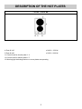
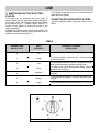
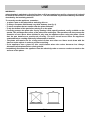
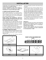
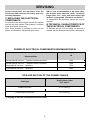
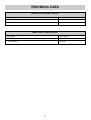
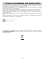
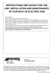
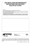
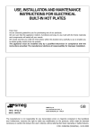
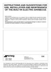
INSTRUCTIONS AND ADVICE FOR THE
USE, INSTALLATION AND MAINTENANCE
OF BUILT-IN ELECTRIC HOBS
Dear Customer,
Thank you for having purchased one of our products.
We are certain that this new, modern, functional and practical appliance, built with the very
highest quality materials, will meet your requirements in the best possible way. This hob is easy
to use. It is, however, important to thoroughly read the instructions in this handbook in order to
obtain the best results.
The manufacturer shall not be held responsible for any damages to persons or property
caused by incorrect installation or use of the appliance.
TIPO: PFZ 02
MOD.: SE32X
SMEG S.p.A.
Via Leonardo da Vinci, 4
42016 GUASTALLA - ITALIA
The Manufacturer shall not be held responsible for any inaccuracies in this handbook due to printing or
transcription errors; the designs in the figures are purely indicative. The Manufacturer also reserves the right
to make any modifications to the products as may be considered necessary or useful, also in the interests
of the user, without jeopardizing the main functional and safety features of the products themselves.
COD. 0101SMN1 (0101UK) - 24.10.2006
DESCRIPTION OF THE HOT PLATES
TYPE: PFZ 02
4 Plate Ø 145
of 1000 ÷ 1500 W
5 Plate Ø 180
of 1500 ÷ 2000 W
11 Control knob for electric plate n° 4
12 Control knob for electric plate n° 5
13 Warning light indicating that one or more plates are operating
2
USE
A red warning light will come on to indicate that the
plate has been ignited.
1) SWITCHING ON THE ELECTRIC
PLATES
The hobs may be equipped with two types of
electric plates: normal and rapid plates indicated by
a red mark. The normal plates and the rapid plates
are controlled by a 7 - position switch (see fig. 1).
Switch on the plates by turning the knob to the
required position.
A diagram is screen-printed on the front panel. This
diagram indicates to which electric plate the knob in
question corresponds (see fig. 1).
2) HOW TO USE THE ELECTRIC PLATES
A purely indicative plate regulation chart is given
below.
TABLE
NORMAL AND
RAPID PLATE
HEAT
INTENSITY
0
Off
1
Weak
To dissolve butter, chocolate, etc.. To heat small
amounts of liquid.
2
Low
To heat larger amounts of liquid. To prepare cremes
and suces requiring long slow cooking times.
3
Slow
To thaw frozen foods and prepare stews, heat to
boiling point or simmer.
4
Medium
To heat foods to boiling point. To brown delicate meats
and fish.
5
Strong
For escalopes and steaks. To simmer large amounts
of food.
6
High
To bring large amounts of liquid to the boil. For frying.
POSSIBLE COOKING
PROCESSES
FIG. 1
3
USE
WARNINGS:
when the plate is switched on for the first time, or if it has remained unused for a long period, it should
be dried for 30 minutes on switch position n° 1. This will eliminate any moisture that may have been
absorbed by the insulating material.
To correctly use the appliance, remember:
- to place a pan on the plate before switching this on.
- To always use pans with flat and very thick bottoms (see fig. 2).
- To never use pans that are smaller than the plate diameters.
- To dry the bottom of the pan before placing it on the plate.
- Correctly preserve the plate after use by treating it with special products, easily available on the
market. This will keep the surface of the plate clean and bright. The operation will also prevent the
formation of rust. Never allow children to play near the appliance when using the plates. Check
that the pan handles are positioned correctly. The user should never leave the appliance
unattended when cooking with easily inflammable oil and fat.
- The plates will remain hot for a long period of time even after use. Never touch them with the
hands or other objects in order to prevent scorching.
- If the appliance has a glass lid, this could shatter when the cooker becomes hot. Always
disconnect all the plates before closing the lid.
- Immediately disconnect the appliance from the electricity main as soon as cracks are noted on the
surfaces of the plates.
FIG. 2
4
CLEANING
WARNINGS:
- correctly preserve the plate after use by
treating it with special products, easily
available on the market. This will keep the
surface of the plate clean and bright. The
operation will also prevent the formation of
rust.
- Any liquid overflowed the pans, must be
always remove with a rag.
- Don’t use steam jets for the equipment
cleaning.
IMPORTANT:
always disconnect the appliance from the
electricity main before carrying out any cleaning
operation.
3) HOTPLATE
If you want to preserve the surface clean and bright,
periodically wash the hot plate with lukewarm soapy
water.
Following this, all parts should be thoroughly rinsed
and dried. Never wash them while they are still
warm and never use abrasive powders.
Do not allow vinegar, coffee, milk, salted water,
lemon or tomato juice from remaining in contact
with the enamelled surfaces for long periods of
time.
5
INSTALLATION
that the transparent protection still adheres to the
seal itself.
- Overturn the hob and correctly position seal “E”
(fig. 5) under the edge of the hob itself, so that
the outer part of the seal itself perfectly matches
the outer perimetral edge of the hob. The ends of
the strips must fit together without overlapping.
- Evenly and securely fix the seal to the hob,
pressing it in place with the fingers and remove
the strip of protective paper from the seal and set
the plate into the hole made in the cabinet.
- Fix the hotplate to the worktop with the brackets
“S”. Ensure the tag fits into the hole “H” on the
hotplate base, then tighten the screw “F” until it is
locked to the worktop (fig. 6).
Installation and maintenance must only be
carried out by a qualified installer.
Incorrect installation could cause damage to
persons, animals and property for which the
manufacturer cannot be held responsible.
4) INSTALLING THE HOT PLATE
Check that the appliance is in a good condition
after having removed the outer packaging and
internal wrappings from around the various loose
parts. In case of doubt, do not use the appliance
and contact qualified personnel.
Never leave the packaging materials
(cardboard, bags, polystyrene foam, nails, etc.)
within children's reach since they could
become potential sources of danger.
The measurements of the opening made in the top
of the modular cabinet and into which the hot plate
will be installed are indicated in either fig. 3, comply
with the measurements given for the hole into which
the appliance will be recessed (see fig. 4).
If a wood is installed above the hob, please look at
the hood manufacturer instructions regarding the
minimum distance between hood and hob (fig. 4).
WARNINGS:
be aware that the glue that join the laminated
plastic to the furniture, has to resist to
temperature not below 150° C, to avoid the
unstuck of the panelling.
The rear wall, adjacent and surrounding
surfaces must therefore be able to withstand
an overtemperature of 65K.
5) FIXING THE HOT PLATE
The hob has a special seal which prevents liquids
from infiltrating into the cabinet. Strictly comply
with the following instructions in order to correctly
apply this seal:
- detach the seals from their backing, checking
COMPLY WITH THE DIMENSIONS
(mm)
2E
A
B
C
285
485
57.5
D
57.5 100 min.
FIG. 3
FIG. 4
FIG. 5
6
E
FIG. 6
INSTALLATION
When the appliance is connected straight to the
electricity main:
- install an omnipolar cutout between the
appliance itself and the main. This circuit-breaker
should be sized according to the rating of the
appliance and the opening between its contacts
should be at least 3 mm.
- Remember that the earth wire must not be cutout
by the switch.
- Alternatively, the electrical connection may also
be protected by a high sensitivity differential
switch.
Installers are strongly advised to connect the
yellow-green earthing wire to an efficient earthing
system.
The manufacturer cannot be responsible for the
missing earthing of the appliance.
6) ELECTRICAL CONNECTIONS
Electrical connection must be carried out in
compliance with the specifications and
provisions in force.
Before proceeding with the connections, check that:
- the voltage rating of the appliance and the
current sockets suits the maximum power draw
of the appliance (see data label affixed to the
lower part of the appliance itself).
- The system is equipped with an efficient earth
connection in compliance with the pertinent
provisions in force. The manufacturer declines all
responsibility for failure to comply with these
provisions.
- If the appliance has no power cable, connect a
cable of adeguate section to the terminal strip
(consult the table on next page) complying with
the wiring diagram of fig. 7. This diagram is also
affixed to the hot plate.
When connection to the electricity main is made
by using a socket (gas version only):
- fit a standard plug to power cable (if supplyied).
This plug should be able to bear the load
indicated on the data label. Connect the wires
according to the diagram in fig. 7, remembering
to comply with the following instructions:
WARNINGS:
all our appliances are designed and
manufactured in compliance with European
standards EN 60 335-1 and EN 60 335-2-6 plus
the relative amendments.
The appliance complies with the provisions of
the following EEC Directives:
- CEE 89/336 + 92/31 + 93/68 regarding to
electromagnetic compatibility.
- CEE 73/23 + 93/68 regarding electrical safety.
letter L (live) = brown wire;
letter N (neutral) = blue wire;
earth symbol
= yellow-green wire.
1
- The powering cable must be positioned so that it
is never able to reach an overtemperature of 65K
in any part.
- Never use reductions, adapters or shunts for the
connection since these could cause false
contacts and dangerous overheating.
- The outlet must be accessible after the built-in.
FIG. 7
7
SERVICING
N.B. In case of substitution of the input cable,
the installer must keep the “earth” conductor
longer than “live” ones, and must respect the
cautions in paragraph “Electrical connection”.
To reassemble the appliance repeat the inverse
process.
Always disconnect the appliance from the
electricity main before proceeding with any
servicing operation.
7) REPLACING THE ELECTRICAL
COMPONENTS
For access to the various parts, remove the hotplate
from the top of the cabinet. Then overturn it, unscrew
screw and remove under part.
After these actions is possible to work on the
plates, commutators, clamps and input cable.
8) TECHNICAL CHARACTERISTICS OF
THE ELECTRICAL COMPONENTS
To facilitate the job of the installer we present a
scheme with the characteristics of the components.
POWER OF ELECTRICAL COMPONENTS DENOMINATIONS W
W
Denominations
Normal plate Ø 145 mm – 7 positions with the protector
1000
Normal plate Ø 180 mm – 7 positions with the protector
Rapid plate Ø 145 mm – 7 positions
1500
1500
Rapid plate Ø 180 mm – 7 positions
2000
TYPE AND SECTION OF THE POWER CABLES
Cable type
Single phase power
230 - 240 V~
Rubber H05 RR-F
3 X 1.5 mm2 (*)
Polycroropene H05 RN-F
3 X 1.5 mm2 (*)
(*) keeping in mind the contemporaneousness factor
8
TECHNICAL DATA
MODEL WITH 2 NORMAL PLATES
VOLTAGE
230 - 240 V~
FREQUENCY
50/60 Hz
TOT. RATING
2500 W
MODEL WITH 2 RAPID PLATES
VOLTAGE
230 - 240 V~
FREQUENCY
50/60 Hz
TOT. RATING
3500 W
9
TECHNICAL ASSISTANCE AND SPARE PARTS
This appliance, before leaving the factory, has been carefully tested and regulated by expert and
specialized personnel in order to guarantee the best performances.
Any repairs or adjustments which may be subsequently required may only be carried out by qualified
personnel with the utmost care and attention.
For this reason, always contact your Dealer or your nearest After Sales Centre whenever repairs or
adjustments are required, specifying the type of fault and the model of appliance in your possession.
Please also note that genuine spare parts are only available from our After Sales Service Centres and
authorized retail outlets.
The above data are printed on the data label put on the inferior part of the appliance and on the packing
label.
The above informations give to the technical assistant the possibility to get fit spare parts and a heavensent intervention. We suggest to fill the table below.
MARK: .............................……….
MODEL: ...........................……….
SERIES: ...........................……….
This appliance is marked according to the European directive 2002/96/EC on Waste Electrical and
Electronic Equipment (WEEE).
This guideline is the frame of a European-wide validity of return and recycling on Waste Electrical and
Electronic Equipment.
10